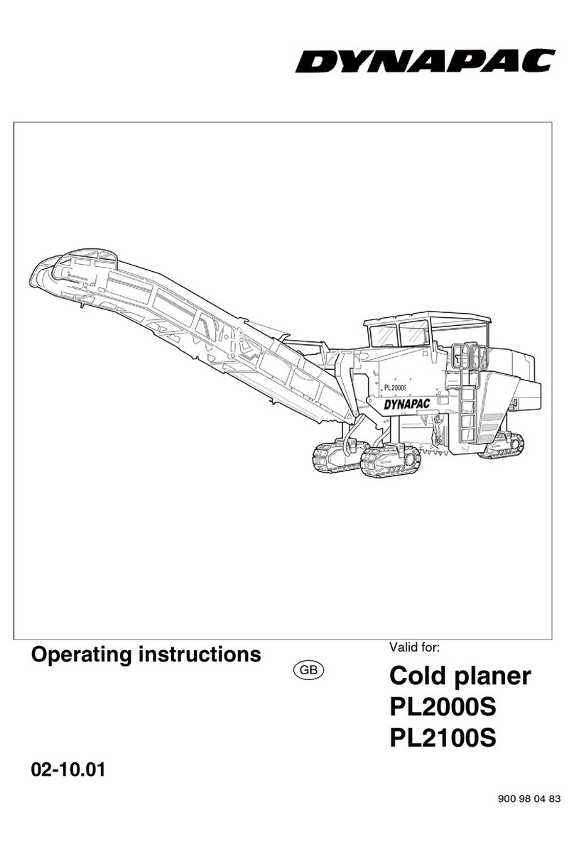
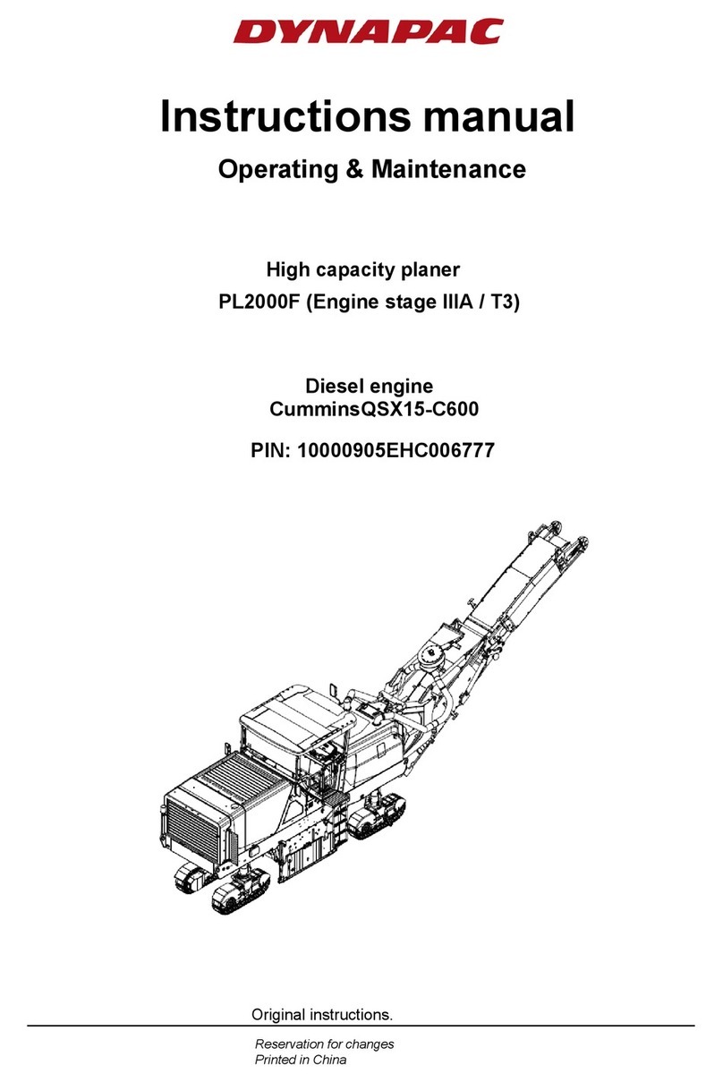
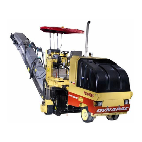
Dynapac PL350 TD User manual

Instructions manualInstructions manual
IPL350TD-1EN2.pdfIPL350TD-1EN2.pdf
Operating & MaintenanceOperating & Maintenance
PlanerPlaner
PL350 TDPL350 TD
Diesel engineDiesel engine
Cummins B3.3Cummins B3.3
Serial numberSerial number
10000900x0A006571 - 10000900x0A006571 -
Translation of original instructions.Translation of original instructions.
Reservation for changesReservation for changes
Printed in SwedenPrinted in Sweden


2000h-Maintenance
IPL350TD-1EN2.pdf2012-06-18
Table of Contents
Introduction .............................................................................................................................. 1
The machine ............................................................................................... 1
Intended use ............................................................................................... 1
Warning symbols......................................................................................... 2
General ....................................................................................................... 2
Safety - General instructions.................................................................................................... 3
Safety - when operating ........................................................................................................... 5
Risk zones on the machine ......................................................................... 5
Slopes ......................................................................................................... 6
Safety (Optional) ...................................................................................................................... 7
Conveyor (option)........................................................................................ 7
Special instructions .................................................................................................................. 9
Standard lubricants and other recommended oils and fluids ...................... 9
Higher ambient temperatures, above +40°C (104°F).................................. 9
Lower ambient temperature - Freeze risk ................................................... 9
Temperatures.............................................................................................. 9
High pressure cleaning ............................................................................. 10
Fire fighting ............................................................................................... 10
Battery handling ........................................................................................ 10
Jump starting (24V)................................................................................... 11
Technical specifications ......................................................................................................... 13
Vibrations - Operator station ..................................................................... 13
Noise level................................................................................................. 13
Dimensions, side view............................................................................... 14
Dimensions, top view ................................................................................ 15
Weights and volumes................................................................................ 16
Working capacity....................................................................................... 16
General ..................................................................................................... 17
Tightening torque ...................................................................................... 18
Machine description ............................................................................................................... 19

2000h-Maintenance
IPL350TD-1EN2.pdf 2012-06-18
Identification ............................................................................................................ 19
Explanation of 17PIN serial number.......................................................... 19
Product identification number on the frame .............................................. 19
Machine plate............................................................................................ 20
Decals...................................................................................................................... 21
Positioning of labels, right-hand side ........................................................ 21
Positioning of labels, left-hand side........................................................... 21
Safety decals............................................................................................. 23
Info decals................................................................................................. 24
Instruments/Controls ............................................................................................... 25
Control panel and controls ........................................................................ 25
Functional description of control panel...................................................... 26
Electrical system...................................................................................................... 28
Main fuses................................................................................................. 28
Fuses, machine......................................................................................... 29
Relays, machine........................................................................................ 29
Functional description.............................................................................................. 30
Front plate ................................................................................................. 30
Footplate extension (option)...................................................................... 30
Driver´s seat (option)................................................................................. 31
Conveyor belt (option)............................................................................... 31
Rear door .................................................................................................. 32
Safety switch ............................................................................................. 33
Working lights............................................................................................ 34
Vandalism protection................................................................................. 35
Stop valve, milling drum freewheel ........................................................... 35
Bits - Tool holder ....................................................................................... 35
Typical wear marks on tool holder ............................................................ 36
Typical wear marks on bits........................................................................ 36
Bits - Checking - Fitting/Removing........................................................... 37

2000h-Maintenance
IPL350TD-1EN2.pdf2012-06-18
Tool holder - Checking/Replacing ............................................................. 38
Operation ............................................................................................................................... 39
Before starting ......................................................................................................... 39
Safety switch - Operation .......................................................................... 39
Steering wheel - Adjustment ..................................................................... 39
View .......................................................................................................... 40
Driver seat - Adjustment (option) .............................................................. 40
Unlock the vandalism protection ............................................................... 40
Master switch - Switching on..................................................................... 41
Starting .................................................................................................................... 42
Starting the engine .................................................................................... 42
Operation................................................................................................................. 43
Positioning................................................................................................. 43
Driving the machine .................................................................................. 43
Driving on difficult surfaces ....................................................................... 44
Drive wheels.............................................................................................. 44
Swivel chassis leg. .................................................................................... 45
Direction of steering indicator.................................................................... 45
Pointer....................................................................................................... 45
Milling/Levelling ....................................................................................................... 46
Milling depth indicator, adjustment............................................................ 46
Milling depth indicator Position stop.......................................................... 47
Flow valve ................................................................................................. 47
Ballast rear - Adjusting machine weight .................................................... 48
Ballast front - Adjusting machine weight ................................................... 48
Milling instructions..................................................................................... 49
Milling position........................................................................................... 49
Resetting milling depth.............................................................................. 49
Surface milling........................................................................................... 50
Milling at edge of roadway or at shoulders................................................ 50

2000h-Maintenance
IPL350TD-1EN2.pdf 2012-06-18
Milling at curb edge with folded out chassis leg. ....................................... 51
Milling at curb edge with folded in chassis leg. ......................................... 51
Milling preparations ................................................................................... 52
Milling ........................................................................................................ 53
Stop milling................................................................................................ 53
Braking .................................................................................................................... 54
Normal braking.......................................................................................... 54
Parking brake ............................................................................................ 54
Reserve brake........................................................................................... 54
Emergency braking ................................................................................... 55
Parking .................................................................................................................... 55
Parking/Switching off................................................................................. 55
Master switch ............................................................................................ 55
Cleaning the machine ............................................................................... 56
Long-term parking.................................................................................................................. 57
Battery....................................................................................................... 57
Engine ....................................................................................................... 57
Watering system ....................................................................................... 57
Hoods, tarpaulin ........................................................................................ 57
Miscellaneous ........................................................................................................................ 59
Lifting ....................................................................................................................... 59
Lifting the planer........................................................................................ 59
Towing/Recovery..................................................................................................... 60
Releasing the brakes ................................................................................ 60
Towing the planer...................................................................................... 61
Transport ................................................................................................................. 61
Machine prepared for transport................................................................. 61
Preventive maintenance ........................................................................................................ 63
Acceptance and delivery inspection.......................................................... 63
Warranty.................................................................................................... 63

2000h-Maintenance
IPL350TD-1EN2.pdf2012-06-18
Maintenance - Lubricants and symbols ................................................................................. 65
Maintenance - Maintenance schedule ................................................................................... 67
Service and maintenance points ............................................................... 67
General ..................................................................................................... 67
Every 10 hours of operation (Daily)........................................................... 68
Every 50 hours of operation (Weekly)....................................................... 69
After the FIRST 250 hours of operation. ................................................... 69
Every 250 hours of operation (Monthly) .................................................... 69
Every 500 hours of operation (Every three months) ................................. 70
Every 1000 hours of operation (Every six months) ................................... 70
Every 2000 hours of operation (Yearly) .................................................... 70
Maintenance, 10h .................................................................................................................. 71
Diesel engine - Check oil level/Filling........................................................ 71
Hydraulic reservoir - Check fluid level....................................................... 72
Fuel tank - Filling....................................................................................... 72
Check the high-pressure hydraulic filter.................................................... 73
Check return filter - suction side................................................................ 73
Water tank - filling ..................................................................................... 74
Sprinkler system/nozzles
Checking/Cleaning .................................................................................... 74
Water filter - Checking/Replacing.............................................................. 75
Clean cooler .............................................................................................. 75
Check level, radiator ................................................................................. 76
Brake function/Emergency stop - Check................................................... 76
Check safety switches............................................................................... 77
Diesel engine - Checking the drive belt..................................................... 78
Maintenance - 50h ................................................................................................................. 79
Air cleaner - emptying ............................................................................... 79
Drive wheel, Planetary gear - Check of oil level........................................ 79
Check rubber seal - Milling housing .......................................................... 80

2000h-Maintenance
IPL350TD-1EN2.pdf 2012-06-18
Crown wheel - Front wheel ....................................................................... 81
Side plates - Check ................................................................................... 81
Side plates - Replacement ........................................................................ 82
Maintenance - 250h ............................................................................................................... 83
Battery
Checking the electrolyte level ................................................................... 83
Slide rails - Check ..................................................................................... 84
Milling depth, limit position ........................................................................ 85
Diesel engine - Oil change - Filter replacement ........................................ 85
Check - Replace air cleaner's filter element.............................................. 86
Air cleaner
- Cleaning.................................................................................................. 87
Maintenance - 500h ............................................................................................................... 89
Fuel filter - Replacement ........................................................................... 89
Fuel filter - Bleeding the filter .................................................................... 90
Hydraulic reservoir cap - Check ................................................................ 91
Hydraulic hoses
Check ........................................................................................................ 91
Water tank - Emptying / Cleaning ............................................................. 92
Maintenance - 2000h ............................................................................................................. 93
Fuel tank - Drainage.................................................................................. 93
Hydraulic reservoir
Fluid change.............................................................................................. 94
Return oil filter suction side
Replacement ............................................................................................. 95
Drive wheel - Planetary gear, oil draining ................................................. 96
High-pressure hydraulic filter - Replacement ............................................ 96
Milling drum - Removal ............................................................................. 97

Introduction
IPL350TD-1EN2.pdf2012-06-18
Introduction
The machine
Dynapac's PL 350 TD planer is a compact, easy to
operate three-wheeled planer with optional all-wheel
drive.
The machine has hydrostatic drives, variably
adjustable in 2 speed ranges and hydraulic steering
(Orbitrol)
The machine has a maximum milling depth of 100 mm.
The right chassis leg can be folded in for precision
milling along curbes etc.
The very tight turning radius makes it possible, for
example, to mill around man holes.
Extra weights (ballast) can, if necessary, be removed
from the machine to provide additional stability when
milling on various surfaces.
Intended use
PL 350 TD is mainly intended to be used for
roadworks:
• to remove layers of asphalt, asphalt concrete and
concrete.
• remove superficial irregularities in the form of ruts, lateral
unevenness and distortions
• to restore the correct surface profile
• roughen up and remove markings
• to carry out preparations in conjunction with laying piping
and conduits
The above work requires the underlying surface to be
sufficiently stable and strong to withstand the
movement of the planer.
The machine is not designed to be used as a towing
machine, a winch or lifting device. See "Safety Manual
for Planing".
The machine is not intended for using in explosive
atmosphere.
1

Introduction
IPL350TD-1EN2.pdf 2012-06-18
Warning symbols
WARNING ! Marks a danger or a hazardous
procedure that can result in life threatening or
serious injury if the warning is ignored.
WARNING ! Marks a danger or a hazardous
procedure that can result in life threatening or
serious injury if the warning is ignored.
CAUTION ! Marks a danger or hazardous
procedure that can result in damage to the
machine or property if the warning is ignored.
CAUTION ! Marks a danger or hazardous
procedure that can result in damage to the
machine or property if the warning is ignored.
General
This manual contains instructions for machine
operation and maintenance.
The machine must be correctly maintained for
maximal performance.
The machine should be kept clean so that any
leakages, loose bolts and loose connections are
discovered at as early a point in time as possible.
Inspect the machine every day, before starting.
Inspect the entire machine so that any leakages or
other faults are detected.
Check the ground under the machine. Leakages are
more easily detected on the ground than on the
machine itself.
THINK ENVIRONMENT ! Do not release oil,
fuel and other environmentally hazardous
substances into the environment. Always send
used filters, drain oil and fuel remnants to
environmentally correct disposal.
THINK ENVIRONMENT ! Do not release oil,
fuel and other environmentally hazardous
substances into the environment. Always send
used filters, drain oil and fuel remnants to
environmentally correct disposal.
This manual contains instructions for periodic
maintenance normally carried out by the operator.
Additional instructions for the engine can be
found in the manufactuer's engine manual.
Additional instructions for the engine can be
found in the manufactuer's engine manual.
2

Safety - General instructions
IPL350TD-1EN2.pdf2012-06-18
Safety - General instructions
(Also read the safety manual)
1. Read the entire manual before starting the machine and before carrying out
any maintenance. Do not remove the manual from the machine. Replace the
instruction manual if lost, damaged or unreadable.
1. Read the entire manual before starting the machine and before carrying out
any maintenance. Do not remove the manual from the machine. Replace the
instruction manual if lost, damaged or unreadable.
2. The safety manual supplied with the machine must be read by all planer
operators. Always follow the safety instructions. Do not remove the manual
from the machine.
2. The safety manual supplied with the machine must be read by all planer
operators. Always follow the safety instructions. Do not remove the manual
from the machine.
3. Only trained and/or experienced operators should be allowed to drive the
planer. It is prohibited to take passengers on the planer.
3. Only trained and/or experienced operators should be allowed to drive the
planer. It is prohibited to take passengers on the planer.
4. Never use the planer if it is in need of adjustment or repair.4. Never use the planer if it is in need of adjustment or repair.
5. Only climb up or down from the planer when it is stationary. Use the
intended grips and rails. Always use the three-point grip (both feet and one
hand, or one foot and both hands) when mounting or dismounting from the
machine. Never jump down from the machine.
5. Only climb up or down from the planer when it is stationary. Use the
intended grips and rails. Always use the three-point grip (both feet and one
hand, or one foot and both hands) when mounting or dismounting from the
machine. Never jump down from the machine.
6. Drive carefully on sharp bends.6. Drive carefully on sharp bends.
7. Avoid driving across slopes. Drive straight up or straight down the slope.7. Avoid driving across slopes. Drive straight up or straight down the slope.
8. Make sure that the underlying surface is sufficiently stable.8. Make sure that the underlying surface is sufficiently stable.
9. Make sure that there are no obstacles in the direction of travel, on the
ground, in front of or behind the planer, or overhead.
9. Make sure that there are no obstacles in the direction of travel, on the
ground, in front of or behind the planer, or overhead.
10. Drive particularly carefully on uneven ground.10. Drive particularly carefully on uneven ground.
11. Use the safety equipment provided.11. Use the safety equipment provided.
12. Keep the planer clean. Immediately remove any dirt or grease from the
operator platform. Keep all signs and labels clean and fully legible. Replace
damaged plates and labels.
12. Keep the planer clean. Immediately remove any dirt or grease from the
operator platform. Keep all signs and labels clean and fully legible. Replace
damaged plates and labels.
13. Safety measures before refueling:
- Shut off the engine
- Do not smoke
- No naked flame in the vicinity of the machine
- Ground the filling device nozzle to the tank to avoid sparks
13. Safety measures before refueling:
- Shut off the engine
- Do not smoke
- No naked flame in the vicinity of the machine
- Ground the filling device nozzle to the tank to avoid sparks
14. Before carrying out repairs or service:
- Place chocks at the wheels
14. Before carrying out repairs or service:
- Place chocks at the wheels
15. Hearing protection is recommended if the noise level exceeds 80 dB(A). The
noise level can vary depending on the equipment on the machine and the
surface the machine is being used on.
15. Hearing protection is recommended if the noise level exceeds 80 dB(A). The
noise level can vary depending on the equipment on the machine and the
surface the machine is being used on.
3

Safety - General instructions
IPL350TD-1EN2.pdf 2012-06-18
16. Do not make any changes or modifications to the planer, this could put
safety at risk. Changes may only be made following the written approval of
Dynapac.
16. Do not make any changes or modifications to the planer, this could put
safety at risk. Changes may only be made following the written approval of
Dynapac.
17. Avoid using the planer before the hydraulic fluid has reached its normal
working temperature. Braking distances can be longer than normal when the
fluid is cold. See instructions in the STOP section.
17. Avoid using the planer before the hydraulic fluid has reached its normal
working temperature. Braking distances can be longer than normal when the
fluid is cold. See instructions in the STOP section.
18. For your own safety, always wear:
- a helmet
- work shoes with steel toecaps
- hearing protection
- breathing protection while milling, if necessary
- reflective clothing/high visibility vest
- work gloves
- eye protection, if necessary
18. For your own safety, always wear:
- a helmet
- work shoes with steel toecaps
- hearing protection
- breathing protection while milling, if necessary
- reflective clothing/high visibility vest
- work gloves
- eye protection, if necessary
19. Ensure sufficient ventilation (extraction of air by fan) where the engine is
run poorly ventilated spaces.
19. Ensure sufficient ventilation (extraction of air by fan) where the engine is
run poorly ventilated spaces.
4

Safety - when operating
IPL350TD-1EN2.pdf2012-06-18
Safety - when operating
Prevent persons from entering or remaining in
the danger area, i.e. a distance of at least 7 m
(23 ft) in all directions from operating machines.
Prevent persons from entering or remaining in
the danger area, i.e. a distance of at least 7 m
(23 ft) in all directions from operating machines.
The operator may allow a person to remain in
the danger area, but should then observe
caution and operate the machine only when the
person is visible or has given clear indications
of where he or she is.
The operator may allow a person to remain in
the danger area, but should then observe
caution and operate the machine only when the
person is visible or has given clear indications
of where he or she is.
Risk zones on the machine
Within these areas there is a risk of being retracted or
crushed as a result of rotating, feeding or moving parts.
5

Safety - when operating
IPL350TD-1EN2.pdf 2012-06-18
Slopes
Fig. Operating on slopes
Maximum permitted angle of
inclination 10°
Maximum permitted angle of
inclination 10°
The values specify the maximum permitted angle of
inclination when driving.
Bear in mind that loose ground, steering angle, the
deflection of the conveyor belt, chassis legs folded in
and the operating speed can change the center of
gravity can cause the machine to tip over on slopes
with lower gradients.
Follow the recommendations for maximum
permitted angle in the picture.
Follow the recommendations for maximum
permitted angle in the picture.
Safety cannot be guaranteed when the max.
permitted angle of inclination is exceeded.
Safety cannot be guaranteed when the max.
permitted angle of inclination is exceeded.
Where possible, avoid driving across slopes.
Drive instead straight up and down sloping
ground.
Where possible, avoid driving across slopes.
Drive instead straight up and down sloping
ground.
6

Safety (Optional)
IPL350TD-1EN2.pdf2012-06-18
Safety (Optional)
Conveyor (option)
The machine should not be transported with
material on the conveyor belt.
The machine should not be transported with
material on the conveyor belt.
The operator must make sure that nobody is in
the working area while the machine is in use.
The operator must make sure that nobody is in
the working area while the machine is in use.
Risk of body and crush injuries. The conveyor
has rotating parts.
Risk of body and crush injuries. The conveyor
has rotating parts.
Risk of being retracted. Rotating conveyor.Risk of being retracted. Rotating conveyor.
The overall length of the machine is changed
when the conveyor is fitted.
The overall length of the machine is changed
when the conveyor is fitted.
7

Safety (Optional)
IPL350TD-1EN2.pdf 2012-06-18
8

Special instructions
IPL350TD-1EN2.pdf2012-06-18
Special instructions
Standard lubricants and other recommended
oils and fluids
Before leaving the factory, the systems and
components are filled with the oils and fluids specified
in the lubricant specification. These are suitable for
ambient temperatures in the range -15°C to +40°C
(5°F - 105°F).
The maximum temperature for biological
hydraulic fluid is +35°C (95°F).
The maximum temperature for biological
hydraulic fluid is +35°C (95°F).
Higher ambient temperatures, above +40°C
(104°F)
For operation of the machine at higher ambient
temperatures, however maximum +50°C (122°F), the
following recommendations apply:
The diesel engine can be run at this temperature using
normal oil. However, the following fluids must be used
for other components:
Hydraulic system - mineral oil Shell Tellus T100 or
similar.
Lower ambient temperature - Freeze risk
Make sure that the watering system is empty/drained
of water (sprinkler, hoses, tank/s) or that anti-freeze
has been added, to prevent the system freezing.
Temperatures
The temperature limits apply to standard versions of
planers.
Planers equipped with additional equipment, such as
noise suppression, may need to be more carefully
monitored in the higher temperature ranges.
9

Special instructions
IPL350TD-1EN2.pdf 2012-06-18
High pressure cleaning
Do not spray directly onto electrical components.
Do not use high pressure cleaning for
dashboard/display.
Do not use high pressure cleaning for
dashboard/display.
The Electrical Drive Control and the computer
box may not be washed with high pressure
cleaning and not at all with water. Clean them
with a dry wiper.
The Electrical Drive Control and the computer
box may not be washed with high pressure
cleaning and not at all with water. Clean them
with a dry wiper.
Detergent that can destroy electrical parts, or
which is conductive, must not be used.
Detergent that can destroy electrical parts, or
which is conductive, must not be used.
Place a plastic bag over the fuel filler cap and secure
with a rubber band. This is to avoid high pressure
water entering the vent hole in the filler cap. This could
cause malfunctions, such as the blocking of filters.
Never aim the water jet directly at the fuel tank
cap. This is particularly important when using a
high-pressure cleaner.
Never aim the water jet directly at the fuel tank
cap. This is particularly important when using a
high-pressure cleaner.
Fire fighting
If the machine catches fire, use an ABC-class powder
fire extinguisher.
A BE-class carbon dioxide fire extinguisher can also
be used.
Battery handling
When removing batteries, always disconnect the
negative cable first.
When removing batteries, always disconnect the
negative cable first.
When fitting batteries, always connect the
positive cable first.
When fitting batteries, always connect the
positive cable first.
Dispose of old batteries in an environmentally
friendly way. Batteries contain toxic lead.
Dispose of old batteries in an environmentally
friendly way. Batteries contain toxic lead.
Do not use a quick-charger for charging the
battery. This may shorten battery life.
Do not use a quick-charger for charging the
battery. This may shorten battery life.
10

Special instructions
IPL350TD-1EN2.pdf2012-06-18
Jump starting (24V)
Do not connect the negative cable to the
negative terminal on the dead battery. A spark
can ignite the oxy-hydrogen gas formed
around the battery.
Do not connect the negative cable to the
negative terminal on the dead battery. A spark
can ignite the oxy-hydrogen gas formed
around the battery.
Check that the battery used for jump starting
has the same voltage as the dead battery.
Check that the battery used for jump starting
has the same voltage as the dead battery.
24V
12V
12V
Fig. Jump starting
1
2
3
4
Turn the ignition and all power consuming equipment
off. Switch off the engine on the machine which is
providing jump start power.
Jump leads must have 24V.
First connect the jump start battery's positive terminal
(1) to the flat battery's positive terminal (2).Then
connect the jump start battery's negative terminal (3)
to, for example, a bolt (4) or the lifjting eye on the
machine with the flat battery.
Start the engine on the power providing machine. Let it
run for a while. Now try to start the other machine.
Disconnect the cables in the reverse order.
Starting gas is not to be used!Starting gas is not to be used!
11

Special instructions
IPL350TD-1EN2.pdf 2012-06-18
12
Table of contents
Other Dynapac Planer manuals