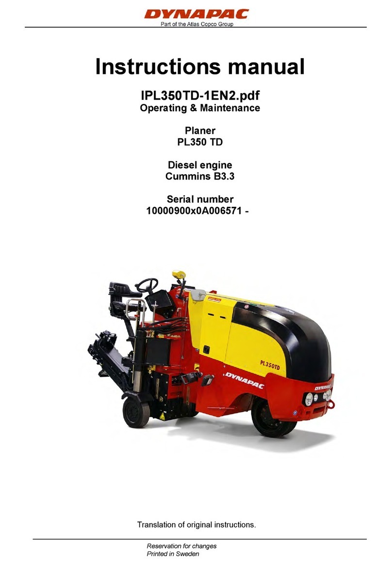
Dynapac PL2000F User manual

Instructions
manual
Operating & Maintenance
High capacity planer
PL2000F (Engine stage IIIA / T3)
Diesel
engine
CumminsQSX15-C600
PIN: 10000905EHC006777
Original instructions.
Reservation for changes
Printed in China


Contents
1
4812313240.pdf
Contents
Instruction.............................................................................................................................................1
The machine........................................................................................................................................1
Intended use........................................................................................................................................2
Warning symbols.................................................................................................................................2
General................................................................................................................................................3
Safety – General instructions..............................................................................................................5
Safety – when operating......................................................................................................................7
Risk zones on the machine..................................................................................................................7
Slopes (Tip over risk)...........................................................................................................................8
Safety devices.....................................................................................................................................9
Conveyor.............................................................................................................................................9
Roof (Option).......................................................................................................................................9
Emergency stop button .....................................................................................................................10
Horn..................................................................................................................................................11
Headlights, Indicators rotary beacons ...............................................................................................12
Hazard warning lights on side panels................................................................................................13
Reverse lights and folding warning signs..........................................................................................13
Traction unit supports.......................................................................................................................14
Steel retaining cables........................................................................................................................15
Retaining hook of scraper flap...........................................................................................................16
Limit switch of scraper flap ...............................................................................................................16
Scraper flap safeguard ......................................................................................................................16
Exit ladders, grab bars and guardrails...............................................................................................17
Side shield.........................................................................................................................................17
Special instructions...........................................................................................................................19
Standard lubricants and other recommended oil and fluids............................................................19
High ambient temperatures, above +40°C (104°F)...........................................................................19
Lower ambient temperature – Freeze risk.......................................................................................19

Contents
2
4812313240.pdf
Temperatures.................................................................................................................................19
High pressure cleaning ..................................................................................................................20
Fire fighting....................................................................................................................................20
Battery handling.............................................................................................................................20
Jumping starting (24V)...................................................................................................................21
Technical specifications........................................................................................................................23
Vibrations – Operator station.............................................................................................................23
Noise level.........................................................................................................................................23
Dimensions .......................................................................................................................................24
Weights.............................................................................................................................................26
Performance data..............................................................................................................................26
Loading system.................................................................................................................................27
Engine (T3)........................................................................................................................................27
Travel drive .......................................................................................................................................27
Hydraulic system...............................................................................................................................28
Water system.....................................................................................................................................28
Compressed air system.....................................................................................................................28
Electrical system...............................................................................................................................28
Tightening torques............................................................................................................................29
Machine description..............................................................................................................................31
Descriptions of assemblies and functions .........................................................................................31
Machine description..........................................................................................................................43
Identification..................................................................................................................................43
Machine plate.................................................................................................................................43
Explanation of 17PIN serial number................................................................................................44
Decals ...............................................................................................................................................45
Safety decals..................................................................................................................................48
Info decals .....................................................................................................................................52
Instruments/Controls.........................................................................................................................53
Control panel .................................................................................................................................53

Contents
3
4812313240.pdf
Switch panel ..................................................................................................................................55
Main console – left & right............................................................................................................55
Control lever panel .......................................................................................................................69
RH/LH – Ergo control....................................................................................................................71
Ground plate panel.......................................................................................................................74
Front left Front right .....................................................................................................................74
Rear left & Rear right....................................................................................................................77
Screen structure for setting and display options............................................................................80
Description of error codes (of page 703), dialog boxes...................................................................97
Electrical system.............................................................................................................................115
Fuses, boxes................................................................................................................................115
Relay, machine.............................................................................................................................116
Driver’s seat on left/right .................................................................................................................117
Battery’s main switch......................................................................................................................118
Batteries ......................................................................................................................................118
Tilt display.......................................................................................................................................119
Lock and Unlock the ground panel cover.........................................................................................120
Folding ladder .................................................................................................................................121
Guardrail .........................................................................................................................................122
Transport position for ladder and guardrails ...................................................................................123
Hydraulic folding roof operation......................................................................................................124
Hydraulic hood operations ..............................................................................................................125
Throttle valves for deployment speed of hood and roof...................................................................126
Manual pump, hood and roof........................................................................................................126
Water system...................................................................................................................................127
High pressure cleaner .....................................................................................................................128
Filling pump for water tank..............................................................................................................129
Water filling (pressure fill) connection for water tank.......................................................................130
Changeover for separate circuits of rear strut towers......................................................................131
Milling depth display .......................................................................................................................132

Contents
4
4812313240.pdf
Milling drum operation check ..........................................................................................................132
Interlock on scraper flap..................................................................................................................133
Retaining hook of scraper flap.........................................................................................................133
Limit switch of scraper flap .............................................................................................................134
Traction unit supports.....................................................................................................................135
Support brackets.............................................................................................................................135
“Scraper flap function changeover” valve .......................................................................................136
“Discharge conveyor function changeover” valve...........................................................................136
Monitoring camera...........................................................................................................................137
Compressed air system (O) .............................................................................................................138
Storage area and protective flaps ....................................................................................................139
Plumb fixture...................................................................................................................................140
Swivel-mounted warning sign..........................................................................................................141
Tool holder......................................................................................................................................141
Typical wear marks on tool holder................................................................................................142
Typical wear marks on bits...........................................................................................................143
Bits holder replacement...............................................................................................................144
Bits replacement..........................................................................................................................147
Replacing the holder box .............................................................................................................148
Leveling unit....................................................................................................................................149
Matric type ...................................................................................................................................149
Operating the Dynapac Leveling System......................................................................................150
Setting the contrast ..................................................................................................................150
Symbols and displays in the working window ..............................................................................151
Sensor selection ..........................................................................................................................152
Operating with the Cross-Slope sensor........................................................................................154
Zero adjustment...........................................................................................................................156
Sensitivity setting ........................................................................................................................158
Changing the measurement units.................................................................................................160
System languages........................................................................................................................161

Contents
5
4812313240.pdf
Operation............................................................................................................................................163
Before starting.................................................................................................................................163
Preparing for operation................................................................................................................163
Devices and aids..........................................................................................................................163
Before starting work.....................................................................................................................164
Starting the machine....................................................................................................................165
External starting (starting aid)......................................................................................................167
Allowing engine to “warm up”......................................................................................................168
Driving the machine .....................................................................................................................169
Milling (preparation).....................................................................................................................170
Parking the machine ....................................................................................................................174
Long-term parking ..............................................................................................................................175
Long-term parking...........................................................................................................................175
Battery.............................................................................................................................................175
Engine.............................................................................................................................................175
Hoods, tarpaulin..............................................................................................................................175
Fuel tank .........................................................................................................................................175
Hydraulic reservoir..........................................................................................................................175
Watering system..............................................................................................................................176
Water pump.....................................................................................................................................176
Miscellaneous.....................................................................................................................................177
Transport.........................................................................................................................................177
Safety regulations for transport....................................................................................................177
Fix points.....................................................................................................................................179
Transport on trailers........................................................................................................................181
Hydraulically foldable discharge conveyor ......................................................................................187
Folding in discharge conveyor.....................................................................................................187
Folding out discharge conveyor...................................................................................................188
Load by crane..................................................................................................................................189
Towing/Retriving .............................................................................................................................190

Contents
6
4812313240.pdf
Short distance towing when the engine is inoperative .....................................................................191
Towing the planer............................................................................................................................192
Lifting the conveyor.........................................................................................................................193
Securing before parking up .............................................................................................................194
Operating instructions – Summary......................................................................................................195
Preventive maintenance......................................................................................................................197
Maintenance – Lubricants and symbols ..............................................................................................199
Maintenance – Lubricants and symbols...........................................................................................199
Fluid volumes..................................................................................................................................199
Maintenance......................................................................................................................................201
Notes regarding safety for maintenance ..........................................................................................201
Liability exclusion in case of use of non-original spare or wear parts as well as incorrect operating
materials .........................................................................................................................................202
Maintenance intervals......................................................................................................................202
Engine drive unit .............................................................................................................................215
Fuel tank .........................................................................................................................................215
Cleaning tank and system ...............................................................................................................216
Diesel engine...................................................................................................................................216
Engine oil drainage point.................................................................................................................217
Oil filter ...........................................................................................................................................218
Fuel filter.........................................................................................................................................218
Fuel filter water separator................................................................................................................219
Air filter ...........................................................................................................................................219
Cooler .............................................................................................................................................220
Coolant filter....................................................................................................................................220
Cooler .............................................................................................................................................221
Drive belt.........................................................................................................................................221
Valve clearance ...............................................................................................................................222
Engine brackets, left/right................................................................................................................222
Connecting screws, pump distribution transmission/engine............................................................223

Contents
7
4812313240.pdf
Hydraulic system.............................................................................................................................224
Hydraulic oil tank.............................................................................................................................224
Hydraulic oil drainage valve.............................................................................................................224
High-pressure hydraulic filter ..........................................................................................................225
Return hydraulic filter......................................................................................................................226
Pump distribution transmission.......................................................................................................227
Oil level check.................................................................................................................................227
Oil cooler.........................................................................................................................................228
Bleeder............................................................................................................................................229
Oil cooler.........................................................................................................................................229
Hydraulic hoses...............................................................................................................................230
Hydraulic unit for roof and hood activation......................................................................................230
Oil level check.................................................................................................................................230
Traction units ..................................................................................................................................231
Planetary gear – oil level check .......................................................................................................231
Oil change.......................................................................................................................................231
Chain tension ..................................................................................................................................232
Bottom plate....................................................................................................................................233
Rubber pad......................................................................................................................................233
Steering system sliding parts, steering arms, stop ring and scraper................................................234
Retaining device for track rod and steering cylinder bolts...............................................................235
Belt drive.........................................................................................................................................235
Clutch “DESCH” Type .....................................................................................................................236
Milling drum gear box......................................................................................................................237
Oil level check.................................................................................................................................237
Oil change.......................................................................................................................................238
Milling drum ....................................................................................................................................239
Draining coolant..............................................................................................................................239
Checking fluid level/adding fluid......................................................................................................240
Scrapers and supporting wear bar (moldboard)...............................................................................240

Contents
8
4812313240.pdf
Runners on the side boards.............................................................................................................241
Sliding shoe runners .......................................................................................................................242
Drum flap limit switch......................................................................................................................243
Milling drum housing fastening bolts...............................................................................................243
Loading equipment..........................................................................................................................244
Belt tension.....................................................................................................................................244
Drum holder ....................................................................................................................................245
Steel cords......................................................................................................................................245
Funnel rubber of transfer point and sealing rubbers/guides ............................................................246
Water system...................................................................................................................................247
Water tank.......................................................................................................................................247
Feed pump ......................................................................................................................................249
Water filter.......................................................................................................................................250
Water pump – Check oil level...........................................................................................................251
Water pump – Drain oil....................................................................................................................251
Spray nozzles..................................................................................................................................252
Power supply...................................................................................................................................253
Batteries..........................................................................................................................................253
Compressed air system...................................................................................................................254
Maintenance unit and compressed air system.................................................................................254
Leveling system ..............................................................................................................................255
Sensor, controllers, connection cables............................................................................................255
Brake system...................................................................................................................................255
Emergency stop button ...................................................................................................................256
Lubrication points .........................................................................................................................257
Traction unit....................................................................................................................................257
Chassis legs....................................................................................................................................257
Steering cylinder .............................................................................................................................257
Floating pin .....................................................................................................................................257
Milling section.................................................................................................................................258

Contents
9
4812313240.pdf
Belt tensioner..................................................................................................................................258
Clutch bearing type “DESCH”..........................................................................................................258
Scraper hydraulic cylinder...............................................................................................................259
Milling drum bearing........................................................................................................................259
Discharge conveyor.........................................................................................................................260
Tail roller pedestal bearing ..............................................................................................................260
Driver roller tension bearing............................................................................................................260
Springs, joints and bolts..................................................................................................................260
Primary conveyor ............................................................................................................................261
Drive roller tension bearing .............................................................................................................261
Inspection .......................................................................................................................................262
General visual inspection ................................................................................................................262
Inspection by an expert ...................................................................................................................262
Disposal ............................................................................................................................................264
Appendix...............................................................................................................................................1
Appendix 1: Engine Fault Code ...........................................................................................................1

Introduction
1
4812313240.pdf
2017-12-1
Introduction
The machine
Dynapac PL2000F is a high performance cold milling
machine for removing asphalt and concrete in a
controlled manner. The track driven machine has a high
capacities discharge conveyor. The milling drum is
driven by heavy duty belts.
As a result of its high milling performance, we would
recommend that this cold planer is used in particular
when carrying out extensive redevelopment work on
large and spacious roads, such as motorways, urban
and country roads, car parks, airports etc.
The PL2000F satisfies very stringent requirements in
terms of its reliability, economic viability and
environmental responsibility.
Technical modifications, attachments and
conversations:
The machine may only be operated with the extension
parts, optional equipment and accessories, protection
and safety devices authorized by the manufacturer as
well as the setting values specified by the
manufacturer. The manufacturer is not liable for
damage resulting from unauthorized changes to the
assemblies, their removal or their replacement with
other, non-intended components or taking them
completely or partially out of operation.
The attachment or installation of additional devices,
which are used to intervene in the function of the cold
planer or with which its function are supplemented, is
only permitted with the written approval of the
manufacturer. If necessary, approval should be sought
from the local authorities.

Introduction
2
4812313240.pdf
2017-12-1
Intended use
PL2000F is mainly intended to be used for roadworks:
to partially or completely remove asphalt,
asphalt based and/or cement layers
to remove distortions in the forms of track
grooves, lateral bulges, lateral warps
to recreate a proper surface
to implement roughing up and striping work
For this, the underlying base layer must be robust
enough to withstand movement of the cold planer.
The transport of outsiders is expressly forbidden, as
using the cold planer as a traction mechanism or lifting
device.
The intended usage also includes compliance with
operating, transport, maintenance and repair
conditions specified in the operating instructions.
The machine is not designed for any type of usage not
described in the intended usage section. The
manufacturer is not liable for such instances of use.
The operator alone bears all risks for such usage.
When in doubt, contact the manufacturer.
Warning symbols
WARNING ! Marks a danger or a hazardous
procedure that can result in life threatening or
serious injury if the warning is ignored
CAUTION ! Marks a danger or hazardous procedure
that can result in damage to the machine or property
if the warning is ignored

Introduction
3
4812313240.pdf
2017-12-1
General
This manual contains instructions for machine safety,
operation, transport and maintenance.
The machine must be correctly maintained for top
performance level.
The machine should be kept clean so that any
leakages, loose bolts and loose connections are
discovered at as early as possible.
Inspect the machine every day, before starting.
Inspect the entire machine so that any leakages or
other faults are detected.
Check the ground under the machine. Leakages are
more easily detected on the ground than on the
machine itself.
THINK ENVIRONMENT ! Do not release oil, fuel and
other environmentally hazardous substances into the
environment. Always send used filters, drain oil and
fuel remnants to environmentally correct disposal.
This manual contains instructions for periodic
maintenance normally carried out by the operator.
Additional instructions for the engine can be found in
the manufacturer’s engine manual.

Introduction
4
4812313240.pdf
2017-12-1

Safety - General instructions
5
4812313240.pdf
2017-12-1
Safety - General instructions
(Also read the safety manual)
1. Read the entire manual before starting the machine and before
carrying out any maintenance. Do not remove the manual from
the machine. Replace the instruction manual if lost, damaged or
unreadable.
2. The safety manual supplied with the machine must be read by
all planer operators. Always follow the safety instructions. Do
not remove the manual from the machine.
3. Only trained and/or experienced operators should be allowed
to drive the planer. It is prohibited to take passengers on the
planer.
4. Never use the planer if it is in need of adjustment or repair.
5. Only climb up or down from the planer when it is stationary. Use
the intended grips and rails. Always use the three-point grip
(both feet and one hand, or one foot and both hands) when
mounting or dismounting from the machine. Never jump down
from the machine.
6. Drive carefully on sharp bends.
7. Avoid driving across slopes. Drive straight up or straight down the
slope.
8. Make sure that the underlying surface is sufficiently stable.
9. Make sure that there are no obstacles in the direction of
travel, on the ground, in front of or behind the planer, or
overhead.
10. Drive particularly carefully on uneven ground.
11. Use the safety equipment provided.
12. Keep the planer clean. Immediately remove any dirt or grease
from the operator platform. Keep all signs and labels clean and
fully legible. Replace damaged plates and labels.
13. Safety measures before refueling:
- Shut off the engine
- Do not smoke
- No naked flame in the vicinity of the machine
- Ground the filling device nozzle to the tank to avoid sparks

Safety - General instructions
6
4812313240.pdf
2017-12-1
14. Hearing protection is recommended if the noise level exceeds
80 dB(A). The noise level can vary depending on the equipment
on the machine and the surface the machine is being used on.
15. Do not make any changes or modifications to the planer, this
could put safety at risk. Changes may only be made following
the written approval of Dynapac.
16. Avoid using the planer before the hydraulic fluid has reached its
normal working temperature. Braking distances can be longer
than normal when the fluid is cold. See instructions in the STOP
section.
17. For your own safety,
always wear:
- a helmet
- work shoes with steel toecaps
- hearing protection
- breathing protection while milling, if necessary
- reflective clothing/high visibility vest
- work gloves
- eye protection, if necessary
18. Ensure sufficient ventilation (extraction of air by fan) where
the engine is run poorly ventilated spaces.

Safety - General instructions
7
4812313240.pdf
2017-12-1
Safety - when operating
Prevent persons from entering or remaining
in the danger area, i.e. a distance of at least
7m (23 ft) in all directions from operating
machines.
The operator may allow a person to remain
in the danger area, but should then observe
caution and operate the machine only when
the person is visible or has given clear
indications of where he or she is.
Fig. Risk zone
Risk zones on the machine
Within these areas there is a risk of being
retracted or crushed as a result of rotating,
feeding or moving parts

Safety - General instructions
8
4812313240.pdf
2017-12-1
Slopes (Tip over risk)
Bear in mind that loose ground, and conveyor
movements changes the center of gravity and
can cause the machine to tip over on slopes
lower than specified.
Follow the stated recommendations for
maximum permitted angle in the picture.
Safety cannot be guaranteed when the max.
permitted angle of inclination is exceeded.
Beforeoperatingyourvehicleinaninclined
position(gradient,slope,lateralinclination)which
isabovethespecifiedlimitvalve,pleaseconsult
thecustomerservicedepartmentforyour
vehicle!
Where possible, avoid driving across slopes.
Drive instead straight up and down sloping
ground
Beforeoperatingyourvehicleinaninclined
position(gradient,slope,lateralinclination)which
isabovethespecifiedlimitvalve,pleaseconsult
thecustomerservicedepartmentforyour
vehicle!
Maximum permitted angle
of inclination 34%
(
19°
)
Maximum permitted angle of
inclination 17%
(
10°
)
Fig. Operating on slopes
19°
10°

Safety - General instructions
9
4812313240.pdf
2017-12-1
Safety devices
The machine can only be safely
operated if the control and safety devices
are functioning perfectly and if the
protective equipment is fitted correctly.
Conveyor
The machine must not be transported
with material on the conveyor. The
weight for the conveyor is specified
on the unit rating plate.
The operator must make sure that
nobody is in the working area while
the machine is in use.
Risk of body and crush injuries.
The conveyor has rotating parts.
Risk of being retracted.
Rotating conveyor
The conveyor must be returned to its
transport position after it has been used.
The overall length of the machine is
changed when the conveyor is fitted.
Roof (Option)
Risk of squeeze risk and crush
injuries.
Table of contents
Other Dynapac Planer manuals