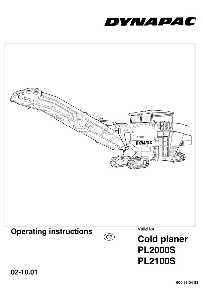
Dynapac PL 1000 RS Troubleshooting guide

502........................
02-0407
OPERATION
&
MAINTENANCE
Keep this manual for future reference
Order number for this manual: 900 98 12 29
Gültig ab Seriennummer:xxx.xxx
Cold Planer
PL 1000 RS

VALUE
QUALITY
THE ORIGINAL
Your Authorizied Dynapac Dealer:
SPARE PARTS

V00.003.D V_PL1000RS_GB.fm- 02.04.07
Preface
If the machines are to be operated safely, the information provided in these Operating
Instructions will be required. The information is shown in a brief and clear form. The
Chapters are ordered by letter. Each Chapter starts with Page 1. The pages are iden-
tified using a Chapter letter and Page number.
Example: Page B 2 is the second page of Chapter B.
To avoid misunderstandings relating to enquiries, consultation sessions, orders, etc.,
always use the terms defined in these Operating Instructions.
These Operating Instructions document various options. During operation and when
carrying out maintenance work, always ensure that the appropriate description for
that option is employed.
The machine may only be operated by trained staff.
These Operating Instructions must be read and applied by every person engaged in
the operation, upkeep (maintenance, repair, servicing) or transport of this device.
These Operating Instructions contain important specifications and information on
how to safely, economically, professionally and correctly use the machine. Compli-
ance helps to prevent dangerous incidents, downtime and repair costs, while also im-
proving operational reliability, extending service life and safeguarding warranty cover.
Safety information and important explanations are identified by the following picto-
grams:
Stands for safety information which must be observed in order to prevent dangers af-
fecting operators.
$Stands for information which must be observed in order to prevent material damage.
Stands for information and explanations.
+
Identifies standard equipment.
&
Identifies optional equipment.

V00.003.D V_PL1000RS_GB.fm- 02.04.07
These Operating Instructions must always be stored in a convenient location on the
machine. They are valid in conjunction with the Dynapac safety manual, the informa-
tion on intended usage and the supplementary operator’s instructions required on the
basis of existing national or regional specifications regarding technical regulations,
accident prevention and environmental protection.
In the interest of further technical development, the manufacturer reserves the right
to undertake modifications while retaining the key features of the machine type de-
scribed and to do so without correcting these Operating Instructions.
Dynapac GmbH
Wardenburg
Ammerländer Strasse 93
D-26203 Wardenburg / Germany
Tel.: +49 / (0)4407 / 972-0
Fax: +49 / (0)4407 / 972-228
www.dynapac.com

1
PL1000RS_GBIVZ.fm 1-6 - 04.07
Table of contents
A Intended usage ........................................................................ 1
B Vehicle description ................................................................. 1
1 Description of usage ..................................................................................1
2 Descriptions of assemblies and functions ..................................................2
2.1 Vehicle ....................................................................................................... 3
Assembly ...............................................................................................3
3 Safety devices ............................................................................................ 5
Emergency-stop button ..........................................................................5
Horn ....................................................................................................... 5
Headlights, flashers, rotary beacons .....................................................6
Retaining hook, moldboard .................................................................... 6
Limit switch on upper conveyor .............................................................7
4 Technical data, standard version ...............................................................8
4.1 Dimensions ................................................................................................8
4.2 Weights ...................................................................................................... 9
4.3 Performance data ......................................................................................9
4.4 Engine ...................................................................................................... 10
4.5 Travel drive .............................................................................................. 10
4.6 Hydraulic system ...................................................................................... 10
4.7 Water system ............................................................................................ 11
4.8 Loading system.........................................................................................11
4.9 Electrical system ......................................................................................11
5 Identification points and type plates ......................................................... 12
5.1 Type plate and vehicle identification number ........................................... 12
Type plate, machine ........................................................................... 13
5.2 Identification points ..................................................................................14
6 European standards .................................................................................17
6.1 Permanent sound-pressure level .............................................................17
6.2 Operating conditions during the measurements ...................................... 17
6.3 Arrangement of measuring points ............................................................ 17
6.4 Vibration acting on the entire body .......................................................... 18
6.5 Vibration acting on the hand-arm .............................................................18
6.6 Electromagnetic compatibility (EMC) ....................................................... 18
C Transport ................................................................................. 1
1 Safety regulations for transport ..................................................................1
2 Fix points .................................................................................................... 2
3 Transport on trailers ................................................................................... 3
4 Normal on-road travel ................................................................................4
5 Loading by crane ....................................................................................... 5
6 Towing procedure ......................................................................................6
7 Secure before parking up ........................................................................... 7

2
PL1000RS_GBIVZ.fm 2-6 - 04.07
D Operation ................................................................................. 1
1 Safety regulations ......................................................................................1
2 Controls ......................................................................................................2
2.1 Control panel .............................................................................................. 2
3 Other controls ..........................................................................................32
3.1 Controls at operator’s control station ....................................................... 32
Driver’s seat .........................................................................................32
Weather protecting sun roof ................................................................33
Side roof .............................................................................................. 33
Weather-protecting sun roof, hydraulic (O) ..........................................34
Battery’s main switch ........................................................................... 35
Batteries ...............................................................................................35
Milling depth display ............................................................................ 36
Swivel-mounted chassis leg ................................................................37
Swivel-mounted chassis leg, hydraulic (o) ...........................................37
Retaining hook, moldboard .................................................................. 38
Water scales / inclination indicator ...................................................... 39
Throttle valve, levelling unit .................................................................40
Load relief of moldboard ...................................................................... 40
Direction of travel indicator .................................................................. 41
Working lights / rotary beacons ...........................................................42
Non-return valves for water spraying / drain valve on water tank ........43
Setting valve for water pressure (water spraying) ...............................44
Steps up to water tank ......................................................................... 44
Chocks .................................................................................................45
Vandalism protection ...........................................................................46
4 Levelling unit ............................................................................................47
4.1 MOBA-matic type .....................................................................................47
5 Operating the MOBA-matic ......................................................................48
6 Operating the MOBA-matic ......................................................................50
6.1 Liquid crystal display (M1) .......................................................................54
Activation message .............................................................................. 54
Sensor message ..................................................................................55
Changeover between height sensor and lateral slope .........................55
LED display .......................................................................................... 56
6.2 Actual value indicator (O) .........................................................................57
Connection: ..........................................................................................59
Connection of MOBA-matic, actual value indicator and sensors ......... 61
Button usage and possible button combinations on the digital
controller during milling ........................................................................ 63
automatic mode - „AUTO“ function lamp on. ......................................63
6.3 Basic settings ........................................................................................... 66
6.4 Calibration to zero ....................................................................................67
Initial situation for calibration to zero ...................................................67
Other tasks .......................................................................................... 67
Calibration to zero for cable tension and Digi-Sonic sensors
when sensing the ground via the side boards. ....................................68
6.5 Actual value calibration ............................................................................69
Digi-Slope sensor (lateral slope sensor) .............................................. 69
Initial situation for actual value calibration ........................................... 69
Other tasks .......................................................................................... 69
Height sensors (to correct the actual value to the value displayed) ....71

3
PL1000RS_GBIVZ.fm 3-6 - 04.07
7 Operation .................................................................................................72
7.1 Preparing for operation ............................................................................72
Devices and aids .................................................................................72
Before starting work ............................................................................. 72
Checklist for machine operator ............................................................73
7.2 Starting the machine ................................................................................ 74
Auxiliary starting (electrical starting aid) .............................................. 76
.............................................................................................................76
Allowing engine to „warm up“ .............................................................. 77
Driving the machine ............................................................................. 78
8 Milling instructions ....................................................................................79
„Driving“ position .................................................................................. 79
„Milling“ position ................................................................................... 79
Zero setting .......................................................................................... 80
Surface milling ..................................................................................... 80
Milling at the edge of the lane or at steps ............................................81
Milling at the curb (with deployed chassis leg) .................................... 81
Milling at the curb (with chassis leg swivelled in) .................................82
Planing without automatic levelling device ..........................................84
8.1 Operating the Moba-matic during milling .................................................86
Initial situation for operation ................................................................. 86
8.2 Other tasks for adopting the initial position for milling: ............................. 87
Milling with height sensors ...................................................................87
Milling with height sensors together with the transverse slope sensor 91
Ending the milling procedure ...............................................................93
Parking the machine ............................................................................ 94
Parking the machine for long periods of time ......................................95
9 Scope for using the small planers ............................................................96
Remedying longitudinal and transverse bumps in the road surface .... 96
Remedying cracks ...............................................................................96
Remedying potholes, frost damage ..................................................... 96
Remedying damage to edges and bumps ...........................................97
Producing adjoining edges .................................................................. 97
Producing slots, joints and cable trenches .......................................... 97
Removing embedded markings ........................................................... 98
Removing road markings ..................................................................... 98
Re-establishing surface grip ................................................................98
10 Malfunctions ............................................................................................. 99
10.1 Error code query for engine ..................................................................... 99
Output of the numerical code ...............................................................99
Error codes ........................................................................................ 101
10.2 Error messages for anti-slip control ....................................................... 109
10.3 Error message from travel drive ............................................................. 110
10.4 MOBA-Matic error messages ................................................................. 111
E Set-up and modification ......................................................... 1
1 Special safety instructions .........................................................................1
2 Planing without upper conveyor / Preparation for transport .......................2
2.1 Dismantling the upper conveyor ................................................................ 2

4
PL1000RS_GBIVZ.fm 4-6 - 04.07
F Maintenance ............................................................................ 1
1 Safety regulations for maintenance ........................................................... 1
2 Liability is rendered null and void if non-genuine spares or wearing
parts or incorrect fuel substances are used. ..............................................2
3 Maintenance intervals ...............................................................................2
3.1 Power unit - engine .................................................................................... 9
Fuel tank ................................................................................................9
Diesel engine .......................................................................................10
Oil changes .......................................................................................... 11
Oil filter .................................................................................................11
Fuel filter .............................................................................................. 12
Draining water from the fuel filter ......................................................... 12
Bleed fuel system ................................................................................13
Air cleaner ...........................................................................................14
Radiator ............................................................................................... 14
Radiator ............................................................................................... 15
Drive belt ..............................................................................................16
3.2 Hydraulics ................................................................................................ 17
Hydraulic oil tank .................................................................................17
Changing the hydraulic oil ...................................................................18
Suction-return hydraulic filter ..............................................................19
Hydraulic hoses ................................................................................... 19
Pump-pedestal .....................................................................................20
3.3 Drive wheels, chassis legs .......................................................................21
Planetary gears ....................................................................................21
3.4 Milling section .......................................................................................... 23
Milling drum .........................................................................................23
Dismantling milling drum ...................................................................... 23
Bits, wearing sleeves, bit blocks .......................................................... 25
SYSTEM KPF201 (o) ........................................................................... 25
SYSTEM KPF301 (o) ........................................................................... 26
Dismantling the bits .............................................................................29
Installing the bits ..................................................................................29
Dismantling the wearing sleeves .........................................................30
.............................................................................................................30
Fitting the wearing sleeves .................................................................. 32
Replacing the bit box ........................................................................... 33
Belt drive ..............................................................................................34
Clutch ...................................................................................................35
Angular gear ........................................................................................ 36
Milling drum gearbox ...........................................................................38
Side boards ..........................................................................................40
Sliding shoes .......................................................................................40
Support plates ...................................................................................... 41
Moldboard / Scraper ............................................................................42
Fräskasten-Schraubenverbindungen ...................................................43

5
PL1000RS_GBIVZ.fm 5-6 - 04.07
3.5 Loading unit ............................................................................................. 44
Belt tension ..........................................................................................44
Steel cables .........................................................................................46
Rubber funnel gasket at transfer point and rubber seals / guides ....... 46
3.6 Water system ........................................................................................... 47
Water tank ........................................................................................... 47
Remove water tank ..............................................................................48
Water filter ........................................................................................... 49
Spray nozzles ......................................................................................50
3.7 Power supply ........................................................................................... 51
Batteries ...............................................................................................51
3.8 Other ........................................................................................................52
Emergency-stop button ........................................................................52
Limit switch on upper conveyor ...........................................................52
Chassis leg guide ................................................................................ 53
4 Lubricating points .....................................................................................54
Chassis leg, right side ..........................................................................54
Steering system ................................................................................... 54
Belt tensioner ....................................................................................... 55
Hydraulic cylinder ................................................................................56
5 Inspections ............................................................................................... 57
General visual inspection .....................................................................57
Inspection by a specialist .....................................................................57
6 Lubrication agents and fuel substances ................................................... 58
6.1 Hydraulic oil ............................................................................................. 59
6.2 Filling volumes .........................................................................................60
7 Electrical fuses .........................................................................................61
7.1 Main fuses (1) (behind the right-hand flap of the engine compartment) .. 61
7.2 Fuses on the operating panel .................................................................. 62
7.3 Fuses in the operating panel ....................................................................64
8 Tightening torques ...................................................................................65
9 Maintenance log .......................................................................................66
Notes on how to fill in the maintenance logs properly: ........................66
9.1 Assembly, engine, engine systems .......................................................... 67
9.2 Hydraulic system ...................................................................................... 68
9.3 Drive wheels, steering system, brakes ....................................................69
9.4 Milling section .......................................................................................... 70
9.5 Water system ........................................................................................... 71
9.6 Electrical system ......................................................................................72
9.7 Other equipment ...................................................................................... 73


A 1
A_PL1000RS_GB.fm 1-2 - 04.07
A Intended usage
The Dynapac „Guideline for the intended and correct usage of cold planers“ falls with-
in the scope of supply of this machine. It forms part of these Operating Instructions
and must be observed. National regulations apply without restriction.
The machine described in these Operating Instructions is a cold planer which can be
used as follows in enclosed building sites on roads:
- for partial removal of asphalt, asphalt-cement and layers of concrete
- to remove distortions in the form of track grooves, lateral bulges, lateral warps,
- to recreate a proper surface,
- to perform roughing and demarcation work,
- for use in preparatory work in pipeline and cable-laying work.
For this, the underlying base layer must be robust enough to withstand movement of
the cold planer.
The transportation of outsiders is expressly forbidden, as is using the cold planer as
a traction mechanism, winch or lifting device.
The intended usage also includes compliance with the operating, transport, mainte-
nance and repair conditions specified in the Operating Instructions.
The machine is not designed for any type of usage not described in the intended us-
age section. The manufacturer is not liable for such instances of use. The operator
alone bears all risks for such usage. When in doubt, contact the manufacturer.
Obligations of the operator: An operator, as defined in these Operating Instruc-
tions, is any natural or judicial person who uses the cold planer himself or on whose
behalf it is used. In special circumstances (e.g. leasing, rental), the operator is that
person who is to observe the specified operating obligations in accordance with the
contractual agreements made between the owner and user of the cold planer.
The operator must ensure that the cold planer is only ever used for its intended pur-
pose and that risks of all kind to the health and safety at work of the operator or third
parties are prevented. Compliance must also be maintained with the accident preven-
tion regulations, all technical safety rules as well as the operating, maintenance and
repair guidelines. The operator must ensure that all users have read and understood
these Operating Instructions.

A 2
A_PL1000RS_GB.fm 2-2 - 04.07
Technical modifications, attachments and conversions: The cold planer may
only be operated with the extension parts, optional equipment and accessories, pro-
tection and safety devices authorised by the manufacturer as well as the setting val-
ues specified by the manufacturer. Autonomous changes to assemblies, their
removal or replacement with other unauthorised parts and any attempt to take these
out of service either completely or partially render null and void the manufacturer’s li-
ability for any resultant damage.
The attachment or installation of additional devices, which are used to intervene in
the function of the cold planer or with which its functions are supplemented, is only
permitted with the written approval of the manufacturer. If necessary, approval should
be sought from the local authorities.
Consent from the authorities is however no substitute for approval from the manufac-
turer.

B 1
B_PL1000RS_GB.fm 1-18 - 04.07
B Vehicle description
1 Description of usage
The DYNAPAC cold planer PL 1000 RS is a compact, very versatile four-wheel cold
planer which is equipped with all-wheel drive, electronic anti-slip control and a single-
section rear loading conveyor.
This cold planer has been developed for tasks such as the cost-effective removal of
asphalt and concrete for medium to large milling operations.
The right-hand chassis leg can be folded in to allow for precision milling of edges.
The PL 1000 RS meets European safety standards and complies with very high
standards in terms of reliability, cost-effectiveness and environmental compatibility.
Iso600_compl.wmf

B 2
B_PL1000RS_GB.fm 2-18 - 04.07
2 Descriptions of assemblies and functions
Item Designation
1Frame
2 Operator’s control station
3 Driver’s seat
4 Drive wheel
5 Chassis leg
6 Swivel-mounted chassis leg
7 Milling depth display
8 Water tank
9 Water spraying system
10 Weather protecting sun roof (
&
)
11 Upper conveyor
PL600_compl.wmf
1
2
3
7
8
9
11
4
6
10
5
7

B 3
B_PL1000RS_GB.fm 3-18 - 04.07
2.1 Vehicle
Assembly
Frame and assembly: Robust, distortion-resistant steel welded design with useful
brackets for supporting the assemblies, units, attachments and tanks. All parts can
be easily accessed for maintenance and repair work.
Operator’s control station: The operator’s control station, conveniently located at
the rear of the machine affording good all-round visibility, can be reached via a ladder
and is equipped with a driver’s seat on the right-hand side.
From the operator’s control station on the right-hand side of the machine, the planer
is easy and safe to operate, affording good visibility and corresponding ease of mon-
itoring for the planing process.
Controls at operator’s control station: A convenient operating and control element
comprising all the requisite switching and display elements.
The securely arranged controls are obviously marked for all applications.
The steering system involves the use of a steering wheel while travel is controlled by
means of a drive lever.
All requisite machine settings such as milling depth and angle adjustment can be per-
formed comfortably from the operator’s control station.
Access to all major switching and connection points, as well as to all maintenance lo-
cations, can be locked.
Engine: The machine is equipped with a powerful 6 cylinder Cummins diesel engine
which effortlessly covers the performance requirements of this planer with its power
rating of 129 Kw.
Compliance is maintained with emission values as defined in the U.S. EPA exhaust
standard and the European COM2 exhaust standard. The engine covers are insulat-
ed from noise as standard, enabling noise emissions to personnel and the surround-
ing area to be reduced to a minimum.
Milling section: The mechanically high-strength V-belt-driven milling drum is located
between the two rear chassis legs. The right-hand chassis leg can be swivelled in
front of the milling drum.
The milling drum rotates in the opposite direction to the machine’s direction of travel.
The professional bit arrangement and equipping with the best cutting tools ensures
rapid and clean milling as well as high bit life.
On the standard drum, with a milling width of 1000 mm, the bit can be replaced via
the rear milling drum flap, thereby keeping downtime to a minimum for replacement
purposes.
The milling drum is bolted to the housing of the mechanical drive and can be replaced
easily and quickly after removing the right-hand housing plate.

B 4
B_PL1000RS_GB.fm 4-18 - 04.07
Milling depth adjustment: Milling depth adjustment is performed hydraulically, and
separately for each rear wheel.
To the left and right sides of the operator’s control station are two clearly legible mill-
ing depth indicators.
Traction system, steering system, travel drive, brake: Suspension of the two front
wheel using a parallelogram-shaped rocker arm ensures an optimum contact surface
at all times. The rear wheels on the chassis legs are designed for the milling adjust-
ment.
The right-hand chassis leg can be swivelled in front of the milling drum.
The hydraulic all-wheel travel drive has continuously variable adjustment across two
speed ranges. The hydraulic travel drives are connected to the wheel hubs by means
of planetary gears. This ensures optimum feed and high gradeability.
A multi-disc brake on the rear wheels acts as brake.
Water system: The water system comprises a water spraying and cooling system.
The water spraying and cooling system operates in the low pressure range. This sys-
tem is used for cooling and jetting the bits.
The spray nozzles can be easily replaced.
The water tank has a high capacity and has good access for filling from the top.
Hydraulic system: The drive unit, actuator functions and steering system are oper-
ated by independent hydraulic circuits ideally suited to the machine.
Electrical system: 24 volt system with two in-line cold-start high-performance batter-
ies and a 3-phase alternator.
The power supply can be interrupted to ground/earth by the battery’s main switch.

B 5
B_PL1000RS_GB.fm 5-18 - 04.07
3 Safety devices
Safe operation is only possible if the operating and safety equipment works perfectly,
and that guards are properly fitted.
The function of these devices must be checked regularly (refer to Chapter D, Section
„Checklists for the machine operator“).
Emergency-stop button
- On the control panel
The engine, drives and steering sys-
tem are shut down when the emergen-
cy-stop button is pressed. Any
countermeasures which may be re-
quired (manoeuvring, deploying the
chassis legs) are then no longer pos-
sible!
$The EMERGENCY STOP button is not
used for normal shut-down of the engine
and should only be used in emergencies
or for inspection purposes.
The traction unit brakes are applied whenever an emergency stop button is pressed!
Horn
- On the control panel
Before starting up the machine, press
the horn button to issue a warning sig-
nal.
Panel2_500_1000.bmp
P
0
I
II
Panel3_600.cdr

B 6
B_PL1000RS_GB.fm 6-18 - 04.07
Headlights, flashers, rotary beacons
Lights for illuminating different operating
areas and for indicating danger areas
and/or dangerous situations are located
at various machine positions.
The machine has two contacts which
can be fitted to the headlights or to the
rotary beacons.
The headlights or rotary beacons are en-
gaged using their respective switches on
the control panel.
The function of the headlights and warn-
ing lamps should be checked on a daily
basis before starting work.
The headlights are easy to remove and
should therefore, as a safety precaution,
be removed at the end of work and
stored in a safe location.
$Headlight contacts which are not used
should be protected using rubber caps.
Retaining hook, moldboard
- Retaining tab on moldboard and re-
taining hook on machine frame en-
gage with one another in raised
position.
Secures the moldboard to prevent it
from being lowered accidentally.
Panel2_600.wmf/Iso600.cdr
Scraper_safety_pl600

B 7
B_PL1000RS_GB.fm 7-18 - 04.07
Limit switch on upper conveyor
A limit switch on the frame of the upper
conveyor prevents unfavourable load
levels arising from excessive raising ac-
tion.
Limit_PL600.wmf

B 8
B_PL1000RS_GB.fm 8-18 - 04.07
4 Technical data, standard version
4.1 Dimensions
2250
1850
840
630
1400
73°
37°
R360
25°
25°
PL1000_measure_side.cdr, PL1000_measure_top.cdr
8550
4350
4100
1060 2360 860
2600
3460
3700
Table of contents
Other Dynapac Planer manuals
Popular Planer manuals by other brands

Mafell
Mafell ZH320 Ec Operating/safety instructions

Villager
Villager VSTP 1525 Original instruction manual

Craftsman
Craftsman 113.206933 owner's manual

DeWalt
DeWalt DW734 instruction manual

Darling Downs Soaring Club
Darling Downs Soaring Club Hornet VH-GKJ Pilot Handling Guide and Conversion Document

DeWalt
DeWalt DW677 instruction manual