Dynaset HWG 220/6K-49 User manual

HWG 180/6K-34
HWG 220/6K-49
HWG 300/10K-54
HWG 400/10K-79
06/18
rev 1.3
HYDRAULIC WELDING GENERATORS
USER MANUAL
Download PDF version from www.Dynaset.com/manuals Keycode: CFJ3SA


Dynaset Oy | Menotie 3, FI-33470 Ylöjärvi, Finland | tlf: +358 3 3488 200 | [email protected] | www.dynaset.com 3
Congratulations!
You have just purchased DYNASET hydraulic equipment!
The equipment allows you to maximize the productivity and
efficiency of your mobile machine. Read this User Manual
before using your new equipment. It contains important
information that will help you to take the full advance of the
technical features avaible in your equipment.
Please contact us for any feedback you might have on our
products. Your feedback is important to us for improving our
products and customer service.
We are constantly developing and releasing new innovations.
Please visit on our website and social media channels for the
latest news and updates.
www.dynaset.com
info@dynaset.com
www.facebook.com/dynaset
www.youtube.com/dynasetoy
www.twitter.com/Dynaset_ofcl
www.instagram.com/dynaset_official
Subscribe to our newsletter. Follow the QR
code!

1. GENERAL 7
1.1. PRODUCT INFORMATION 7
1.2. PRODUCT IDENTIFICATION KEY 7
1.3. TYPE PLATE 8
1.4. HWG LINE-UP 8
1.5. MAIN COMPONENTS OF HWG 9
1.6. IP (Ingress Protection) CLASSIFICATION 10
1.7. VOLTAGE AND FREQUENCY 11
1.8. HYDRAULIC EQUIPMENT 12
1.9. ELECTRIC EQUIPMENT 13
1.9.1. SINGLE PHASE SOCKET PLUG TYPE 14
1.9.2. THREE PHASE SOCKET PLUG TYPE 16
2. SAFETY 17
2.1. SAFETY PRECAUTIONS 17
2.2. SAFETY EQUIPMENT 18
2.3. OPERATING SAFETY 18
2.4. MAINTENANCE SAFETY 20
2.5. WARNING LABELS 21
3. OPERATING PRINCIPLES 23
3.1. OPERATING DESCRIPTION 23
3.2. WELDING PERFORMANCE 23
3.3. AUXILIARY VOLTAGE CONTROL 24
3.4. PERFORMANCE OF AUTOMATIC FREQUENCY CONTROL 24
3.5. PRESSURE POWER RATIO 24
4. INSTALLATION 27
4.1. BEFORE INSTALLATION 27
4.1.1. HYDRAULIC SYSTEM OF A BASE MACHINE 27
4.1.2. DYNASET VALVES 34
4.2. INSTALLING DYNASET HYDRAULIC PRODUCT 35
4.2.1. PLACING DYNASET HYDRAULIC PRODUCT 35
4.2.2. INSTALLING DYNASET VALVES 35
4.2.3. CONNECTING HYDRAULIC HOSES 35
4.2.4. HYDRAULIC FLUIDS 37
HYDRAULIC WELDING GENERATORS
TABLE OF CONTENTS

4.3. INSTALLING HWG HYDRAULIC WELDING GENERATOR 37
4.4. GROUNDING 38
4.5. IP CODE REQUIREMENTS 39
4.6. OUTPUT FREQUENCY INSPECTION AT START-UP 39
5. OPERATION 41
5.1. HWG CONTROL PANEL 41
5.2. STARTING HWG 42
5.3. WELDING PREPARATION 42
5.4. SELECTING WELDING CURRENT WITH HWG 180/220/400 43
5.5. SELECTING WELDING CURRENT WITH HWG 300 43
5.6. WELDING WITH THE HWG 43
5.7. CONNECTING A LOAD TO GENERATOR 44
5.8. STOPPING THE HWG 45
5.9. BATTERY CHARGING AND JUMP STARTING PROCEDURE WITH HWG 300 45
5.10. REMOTE CONTROL 46
5.11. OVERHEATING AND OVERLOAD SITUATION 46
5.12. AMBIENT TEMPERATURE 47
6. MAINTENANCE 49
6.1. MAINTENANCE INTERVALS 49
6.2. HYDRAULIC FLUIDS 49
6.3. CLEANING HWG HYDRAULIC WELDING GENERATOR 50
6.4. TEST SAFETY DEVICES 51
6.5. ADJUSTING OUTPUT FREQUENCY 52
6.6. TROUBLESHOOTING 56
7. MANUFACTURER’S LIMITED WARRANTY 59
8. PRODUCT DISPOSAL 61
9. DECLARATION OF CONFORMITY 63
10. TECHNICAL SPECIFICATIONS 65
HYDRAULIC WELDING GENERATORS
TABLE OF CONTENTS

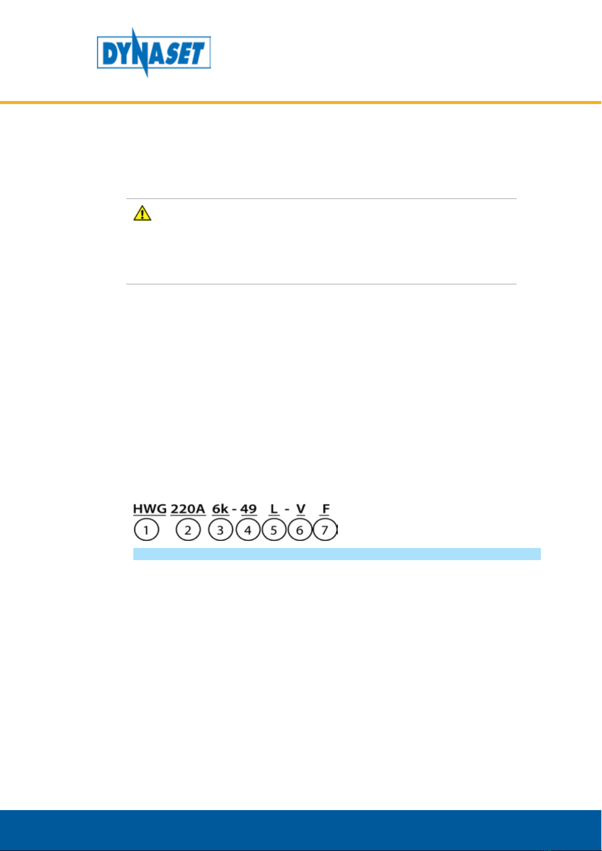
Picture 1: HWG Identication key���������������������������������������������������������������������������������������������������������������������������������������������������������������������������������������������7
Picture 2: HWG type plate�������������������������������������������������������������������������������������������������������������������������������������������������������������������������������������������������������������8
Picture 3: HWG hydraulic welder generator line-up������������������������������������������������������������������������������������������������������������������������������������������������������8
Picture 4: HWG 180/220/300/400 main components ��������������������������������������������������������������������������������������������������������������������������������������������������9
Picture 5: Single phase voltage and frequency world map������������������������������������������������������������������������������������������������������������������������������������� 11
Picture 6: Three phase voltage and frequency world map�������������������������������������������������������������������������������������������������������������������������������������� 12
Picture 7: Single phase sockets and plugs������������������������������������������������������������������������������������������������������������������������������������������������������������������������ 14
Picture 8: Single phase plug and socket world map��������������������������������������������������������������������������������������������������������������������������������������������������� 15
Picture 9: Three phase IP23 plug and socket������������������������������������������������������������������������������������������������������������������������������������������������������������������ 16
Picture 10: HWG operating principlet ��������������������������������������������������������������������������������������������������������������������������������������������������������������������������������� 23
Picture 11: Automatic frequency control��������������������������������������������������������������������������������������������������������������������������������������������������������������������������� 24
Picture 12: Pressure/Power chart������������������������������������������������������������������������������������������������������������������������������������������������������������������������������������������� 25
Picture 13: Open centre hydraulic system with load sensing variable displacement pump���������������������������������������������������������������� 28
Picture 14: Connection gure for open centre hydraulic system with load sensing variable displacement pump���������������� 29
Picture 15: Closed centre hydraulic system with load sensing variable displacement pump�������������������������������������������������������������� 30
Picture 16: Connection gure for closed centre hydraulic system with load sensing variable displacement pump�������������� 31
Picture 17: Hydraulic system with constant displacement pump����������������������������������������������������������������������������������������������������������������������� 32
Picture 18: Connection gure for hydraulic system with xed displacement pump�������������������������������������������������������������������������������� 33
Picture 19: LSV Load sensing valve��������������������������������������������������������������������������������������������������������������������������������������������������������������������������������������� 34
Picture 20: PV-SAE Priority valve�������������������������������������������������������������������������������������������������������������������������������������������������������������������������������������������� 34
Picture 21: Placing DYNASET product���������������������������������������������������������������������������������������������������������������������������������������������������������������������������������� 35
Picture 22: Installing hydraulic hoses���������������������������������������������������������������������������������������������������������������������������������������������������������������������������������� 35
Picture 23: Hydraulic ow at least minimal��������������������������������������������������������������������������������������������������������������������������������������������������������������������� 36
Picture 24: Base machine’s pumps��������������������������������������������������������������������������������������������������������������������������������������������������������������������������������������� 36
Picture 25: Return line (T) pressure must be under 5 bars.������������������������������������������������������������������������������������������������������������������������������������ 36
Picture 26: Placement of the HWG hydraulic welding generator with sucient room and ventilation���������������������������������������� 37
Picture 27: Grounding the HWG hydraulic welding generator������������������������������������������������������������������������������������������������������������������������������ 38
Picture 28: Starting the HWG with control valve���������������������������������������������������������������������������������������������������������������������������������������������������������� 39
Picture 29: Measuring frequency������������������������������������������������������������������������������������������������������������������������������������������������������������������������������������������� 39
Picture 30: HWG models and their control panels�������������������������������������������������������������������������������������������������������������������������������������������������������� 41
Picture 31: Applying the welding cable pliers���������������������������������������������������������������������������������������������������������������������������������������������������������������� 42
Picture 32: Welding ����������������������������������������������������������������������������������������������������������������������������������������������������������������������������������������������������������������������� 43
Picture 33: HWG with connected load�������������������������������������������������������������������������������������������������������������������������������������������������������������������������������� 44
Picture 34: Stopping the HWG ������������������������������������������������������������������������������������������������������������������������������������������������������������������������������������������������ 45
Picture 35: Power take o in higher temperatures������������������������������������������������������������������������������������������������������������������������������������������������������ 47
Picture 36: Cleaning HWG���������������������������������������������������������������������������������������������������������������������������������������������������������������������������������������������������������� 50
Picture 37: Testing the residual current device��������������������������������������������������������������������������������������������������������������������������������������������������������������� 52
Picture 38: Adjusting the frequency������������������������������������������������������������������������������������������������������������������������������������������������������������������������������������� 53
Picture 39: Cartridge tuning without installation valve 1 ��������������������������������������������������������������������������������������������������������������������������������������� 54
Picture 40: Cartridge tuning without installation valve 2-5����������������������������������������������������������������������������������������������������������������������������������� 55
HYDRAULIC WELDING GENERATORS
TABLE OF PICTURES

7
HYDRAULIC WELDING GENERATORS
GENERAL
1. GENERAL
This manual contains general information about the assembly, installation,
operation and maintenance of the DYNASET HWG hydraulic welding generators.
ATTENTION!
Read this user manual before installation, use or maintenance of the HWG
hydraulic welding generator, to ensure proper handling, operation and
maintenance right from the beginning. Pay attention to the warning and
safety instructions. READ CHAPTER ”2. SAFETY” for more information.
1.1. PRODUCT INFORMATION
HWG hydraulic welding generators are compact and integrated all-in-one units,
designed especially for mobile installation. HWG hydraulic welding generators
use hydraulic power source to operate and produce high quality electricity for
welding and powering electric equipment
1.2. PRODUCT IDENTIFICATION KEY
The product identification key describes the characteristics of the DYNASET
product. The product identification key is on the product type plate which is
attached on to every DYNASET product.
Picture 1: HWG Identification key
1. Product group HWG Hydraulic Welding Generators.
2. Maximum welding current.
3. Generator’s theoretical power output in kVA.
4. Nominal hydraulic flow.The theoretical hydraulic flow of the base machine
needed to operate the product.
5. Hydraulic equipment attached to the HWG. READ CHAPTER ”1.8. Hydraulic
equipment” for more information.
6. Electric output equipment attached to the HWG. READ CHAPTER ”1.9.
Electric equipment”for more information.
7. Power output socket types are attached to the HWG. READ CHAPTER ”1.9.1.
Single phase socket plug type”for more information.

8Dynaset Oy | Menotie 3, 33470 Ylöjärvi | puh. 03 3488 200 | [email protected] | www.dynaset.com
HYDRAULIC WELDING GENERATORS
GENERAL
1.3. TYPE PLATE
Picture 2: HWG type plate
1. Product identification key
2. Product code
3. Serial number
4. Minimum hydraulic flow
5. Maximum hydraulic pressure
6. Production month / year
7. Auxiliary output voltage
/ current, frequency,
IP classification.
8. Max. welding current.
9. Manufacturer’s contact
information
1.4. HWG LINEUP
DYNASET HWG come in eight standard models. They vary by their welding current
(180-400A) and auxiliary power output (230V-400V). DYNASET HWG hydraulic
welders are made for 50 Hz as standard. 60 Hz models are available by request.
1. HWG 180/6K - 34
2. HWG 220/6K - 49
3. HWG 300/10K - 54
4. HWG 400/10K - 79
Picture 3: HWG hydraulic welder generator line-up

9
HYDRAULIC WELDING GENERATORS
GENERAL
1.5. MAIN COMPONENTS OF HWG
Picture 4: HWG 180/220/300/400 main components
1. Type plate1
2. Serial number1
3. Hydraulic return line (T)
4. Hydraulic pressure line (P)
5. Hydraulic motor
6. Electric sockets1
7. Residual current device
8. Voltage meter2
9. Fuses
10. Welding cable terminal
11. Welding current range selector1
12. Welding/Generator switch1
1 Place may vary
2Optional
Welding controls of each model are described in chapter 5.

10 Dynaset Oy | Menotie 3, 33470 Ylöjärvi | puh. 03 3488 200 | [email protected] | www.dynaset.com
HYDRAULIC WELDING GENERATORS
GENERAL
1.6. IP Ingress Protection) CLASSIFICATION
HWG hydraulic generators are IP classified according to the IEC standard 60529 for
the degrees of protection of electrical equipment.The protection class of standard
HWG 180/220/300/400 hydraulic generators complies with the specifications IP23.

11
HYDRAULIC WELDING GENERATORS
GENERAL
1.7. VOLTAGE AND FREQUENCY
HWG hydraulic welding generators are manufactured for an output of 21,5-73
VDC welding voltage. Striking voltage being up to 73 VDC and welding between
21,5-36 VDC, depending on the model.
DYNASET HWG welding generators are made as a CC (Constant Current) welding
machines. In this type of welding machine the current is kept constant while the
welding voltage is allowed to change to maintain good welding result.
HWG 180/220/300/400 also have 230V - 400Vac auxiliary outputs. Models are
made for 50 Hz as standard.
The picture 5 represents general single phase voltage and frequency areas in the
world. The picture 6 represents general three phase voltage and frequency areas
in the world.
More information about different countries single and three-phase electric power
usage can be found from the http://www.worldstandards.eu/electricity/
The pictures are based on information on the internet page: http://www.
worldstandards.eu/electricity/plugs-and-sockets.
Picture 5: Single phase voltage and frequency world map

12 Dynaset Oy | Menotie 3, 33470 Ylöjärvi | puh. 03 3488 200 | [email protected] | www.dynaset.com
HYDRAULIC WELDING GENERATORS
GENERAL
NOTE!
Always check that the HWG hydraulic welding generators electric power
output frequency, voltage and sockets are suitable for the use in your
destination.
Picture 6: Three phase voltage and frequency world map
1.8. HYDRAULIC EQUIPMENT
The product identification key describes which options are include in the HWG
hydraulic generator’s structure.
Drain line (L)
An additional drain line can be installed if the pressure in tank line is too high.

13
HYDRAULIC WELDING GENERATORS
GENERAL
NOTE!
The maximum continuous pressure in tank line is 5 bar.
Pressure relief valve (P)
An additional pressure relief valve can be installed on the generators RPM-block.
Pressure release valve prevents oil pressure raising too high.
Rubber cushions (R)
Rubber cushions are attachments between HWG generator and its base machine.
If HWG generator comes with rubber cushions, grounding of the generator have
to be ensured.
NOTE!
READ CHAPTER ”4.4. Grounding” for more information about proper
grounding for the HWG hydraulic welding generators.
Silence-Motor (E)
An additional hydraulic motor option. In this option noise level is reduced. Silence-
motors are used when low noise level is required.
1.9. ELECTRIC EQUIPMENT
The product identification key describes which electric equipment are included in
HWG hydraulic welding generator’s structure.
Every DYNASET HWG hydraulic welding generator with an auxiliary power output
include fuses, either a residual current device (V) or a residual current circuit
breaker (Y). Other electric equipments are optional.
Cable connection (K)
Cable connection model has a cable auxiliary power output connection instead
of a plain socket output. Cable connection models don´t have any electrical
safety devices such as fuses and residual current circuit breakers on them. Cable
connection is available only by request only.
Residual current device (V)
A residual current device (RCD) responds to current leakages by switching the
current off if the current difference between phase and neutral is more than 30
mA.
RCD has a test button to test its proper operation in fault condition. When the test
button is pressed it safely creates a small leakage condition which releases the
switch. RCD is to be tested monthly. READ CHAPTER ”6.4. Test safety devices” for
more information.

14 Dynaset Oy | Menotie 3, 33470 Ylöjärvi | puh. 03 3488 200 | [email protected] | www.dynaset.com
HYDRAULIC WELDING GENERATORS
GENERAL
The RCD (V) includes a residual current circuit breaker device (RCCBD) which
functions are presented in the equipment (Y).
Residual current circuit breaker device (Y)
The Residual current device circuit breaker (RCCBD) is installed in the distribution
box. Each socket in distribution box has its own RCCBD with a reset switch.
Automatic circuit breakers protects the unit from a current overload.
RCCBD also includes a test button. When the button is pressed, it safely creates a
small leakage condition and releases the switch. RCCBD (Y) is integrated into the
RCD which functions are presented in the equipment (V).
Other Electric Equipment
If you have a need for other electrical equipment for your generator please contact
us for more information about the possibilities of upgrading your product.
1.9.1. SINGLE PHASE SOCKET PLUG TYPE
The product identification key describes which socket option includes to the HWG
hydraulic generator’s structure. In the picture 7 are presented all the single-phase
electricity socket types and in the following chart their specification. All delivered
sockets are with covers.
The pictures are from: http://www.worldstandards.eu/electricity/plugs-and-
sockets.
NOTE!
Ungrounded plugs and sockets A,C and I are unavailable.
Picture 7: Single phase sockets and plugs

15
HYDRAULIC WELDING GENERATORS
GENERAL
Type Grounding Current (A) Voltage (V) Socket compatibility with plug(s)
ANot grounded 15 100-127 A
BGrounded 15 100-127 A&B
CNot grounded 2,5 220-240 C
DGrounded 5 220-240 C & D, (Unsafe with E & F)
EGrounded 16 220-240 C, E & F
FGrounded 16 220-240 C, E & F
GGrounded 13 220-240 G
HGrounded 16 220-240 C & H (Unsafe with E & F)
I2 pins: not grounded
3pins:grounded 10 220-240 I
JGrounded 10 220-240 C & J
KGrounded 16 220-240 C & K (Unsafe with E & F)
LGrounded 10
16 220-240 10 A socket: C & L.
16 A socket: L
MGrounded 15 220-240 M
NGrounded 10
20 220-240 C & N
OGrounded 16 220-240 C & O (Unsafe with E & F)
The single phase plugs are also presented in the following picture 8 by their usage
in different parts of the world. Note that the map is for general use only and the
plug & socket types might vary from it.
Picture 8: Single phase plug and socket world map

16 Dynaset Oy | Menotie 3, 33470 Ylöjärvi | puh. 03 3488 200 | [email protected] | www.dynaset.com
HYDRAULIC WELDING GENERATORS
GENERAL
1.9.2. THREE PHASE SOCKET PLUG TYPE
Three phase socket plugs are delivered according to the IEC60309 standard.
Picture 9 shows typical IP23 plug and socket types.
Delivered sockets or plugs might have different color or exterior than in the picture
9. Ask for suitable three phase plug and socket configuration when ordering a
HWG hydraulic welding generator.
Picture 9: Three phase IP23 plug and socket
Nr. Voltage Rated
current
IP
class Hz Number of poles Earthing sleeve
position
1380-415 V 16 A 44 50 3p + n + e 6h
2380-415 V 16 A 44 50 3p + n + e 6h

17
HYDRAULIC WELDING GENERATORS
SAFETY
2. SAFETY
2.1. SAFETY PRECAUTIONS
ATTENTION!
Operator and maintenance personnel must act in compliance with the
laws, regulations and recommendations issued by the local electricity and
work safety authorities.
ATTENTION!
All installations and maintenance must be performed according to this
manual. All electrical installations and maintenance that is not shown in
this manual should only be performed by a qualified electrician.
Operating voltage of the HWG hydraulic welding generators vary from 21,5-73
VDC in welding mode to 230-400Vac in the generator mode.
The hydraulic system can be pressurized up to 420 bar.
WARNING
HIGH PRESSURE OIL!
Can cause severe injuries.
Always wear appropriate clothing
and safety equipment.

18 Dynaset Oy | Menotie 3, 33470 Ylöjärvi | puh. 03 3488 200 | [email protected] | www.dynaset.com
HYDRAULIC WELDING GENERATORS
SAFETY
The pressure in hydraulic circuits is considerably high. Therefore the condition of
your equipment are to be kept under constant observation. All couplings, valves
and hoses are to be kept tight and clean. Leaks in the hydraulic system must be
repaired immediately to avoid injuries caused by high pressure and oil blowouts.
NOTE!
Technical condition of your machinery and equipment must be subjected
to constant surveillance.
Base machine must be stopped and hydraulic circuit depressurized prior to
maintenance,detaching ordisassemblingoftheHWGhydraulicweldinggenerator.
2.2. SAFETY EQUIPMENT
Always wear appropriate clothing and safety equipment such as safety goggles,
safety shoes, ear and eye protection when operating the HWG .
2.3. OPERATING SAFETY
ATTENTION!
Do not exceed the maximum load.
WARNING
RISK OF BURNS!
The unit parts and oil can be hotter
than 80°C!
Wear personal safety equipment!

19
HYDRAULIC WELDING GENERATORS
SAFETY
WARNING
RISK OF ELECTRIC SHOCK!
Electric shock from welding
electrode can kill. Do not weld in
rain or snow. Wear proper dry
insulating safety equipment.
RISK OF ELECTRIC
SHOCK.
WARNING
RISK OF SEVERE EYE INJURY
Arc rays can seriously harm your eyes
and injure skin. Use welding helmet with
correct shade of lter and wear proper
protective gear.
WARNING
RISK INDUCED BY WELDING
FUMES!
Breathing welding fumes can be hazardous
to your health. Use welding equipment in an
open area. Use ventilating fan to remove
fumes.
WARNING
RISK OF FIRE.
Welding sparks can cause explosion
or re. Keep ammable material
away from welding area. Do not
weld in closed containers.

20 Dynaset Oy | Menotie 3, 33470 Ylöjärvi | puh. 03 3488 200 | [email protected] | www.dynaset.com
HYDRAULIC WELDING GENERATORS
SAFETY
WARNING
ELECTROMAGNETIC FIELD
INTERFERENCE
Welding current produces electromagnetic
eld. Do not use with medical implants.
Never coil welding cables around your body.
Ensure also that the electromagnetic field does not interfere or damage other
electrical and electronic equipment and instrumentation. Switch off and unplug
all sensitive electric and electronic units e.g. AC-chargers, electronic sensors,
control and measurement instruments.
2.4. MAINTENANCE SAFETY
NOTE!
When carrying out any maintenance to the HWG hydraulic welding
generator keep the components of the system clean. This is to ensure safe,
reliable and longlife operation of your equipment.
WARNING
RISK OF ELECTRIC SHOCK!
Wait until the charge of the electric parts is
completely discharged before removing
any covers.
Stop and wait at least 10 minutes for
proper discharge.
RISK OF ELECTRIC
SHOCK.
10min
Hydraulic system of a base machine should be maintained according to the
machine’s service program. READ CHAPTER ”6.1. Maintenance Intervals” for more
information.
ATTENTION!
Before beginning any maintenance or repair, ensure that the system is
switched off. Make sure that the system can not start accidentally.
This manual suits for next models
3
Table of contents