Dynisco PG541 User manual

INSTRUCTIONS FOR PLASTIC
MELT PRESSURE GAUGES
The following
models are
covered in this
manual:
PG541
PG542
PG551
PG 552
TPG543
TPG553

Contents
1. Introduction ................................................... 1
1.1. Gauge Probe Mounting Hole ................ 1
1.2. Mounting Hole Dimension Check ......... 2
2. Installation ...................................................... 3
2.1. Gauge Enclosure Rotation..................... 3
2.2. Stem Up - Stem Down Modification ..... 3
2.3. Wiring (all models) ............................... 4
2.4. Terminal Connections ........................... 4
2.5. Alarm Manual/Automatic Reset Option 5
2.6. Alarm Hi/Low Modification
(alarm units only) .................................. 5
2.7. Alarm Relay Ratings .............................. 6
2.8. Power Supply Requirements ................. 6
3. Operation....................................................... 6
3.1. Zero Adjustment (all models) ............... 6
3.2. Alarm Adjustment (PG551-PG552) ..... 6
3.3. Thermocouple Removal & Installation
(TPG543 & TPG553) ............................ 6
4. Integral Power Supply
(P/N 496309 or Option G115).................... 6
5. Removal ......................................................... 7
6. Cleaning.......................................................... 8
7. Warranty and Service .................................... 8

DYNISCO PG500 Series
11
11
1
11
11
1
1. INTRODUCTION
The Dynisco PG540/PG550 Series pressure gauges are highly
engineered, electronic devices. With proper installation and handling
these units will provide years of care-free service.
The tip of the gauge consists of a stainless steel diaphragm. Care must
be taken to protect the diaphragm from severe abrasion, dents and
gouges. During storage the protective cap supplied with the unit
should be left in place.
1.1 Gauge Probe Mounting Hole
The gauge probe is machined to tight dimensional tolerances. To avoid
damage on installation, the mounting hole should be carefully
machined and checked for the correct dimensions.
A set of mounting hole machining tools is available (P/N 200925) to
assist in preparation of the mounting hole.
The mounting hole should conform to the recommended dimensions
shown in Figure 2, below.
Fig. 2 Gauge Probe Mounting Hole

DYNISCO PG500 Series
22
22
2
22
22
2
1.2 Mounting Hole Dimension Check
The proper fit between the pressure probe and mounting well must
be maintained throughout the service life of the gauge and should be
checked periodically. A gauge plug (P/N 200908 - Figure 3) is
available which can be used to check the hole as follows:
1. Referring to Figure 4, paint the clean dry surfaces of the gauge
plug as shown with machinists ink, such as Dykem steel blue
(Note 1).
2. To prevent galling, lubricate the threads with a high temperature
anti-seize compound.
3. Insert the plug and torque lightly until seated in the well.
4. Remove and carefully examine the plug. Except for the 45°
chamfered surface, the Dykem should be intact. If marred, it is an
indication of some type of mechanical interference which must be
corrected before the transducer is installed.
5. Typical interference problems are:
Burrs or chips in the hole ............................... Remove
Undersized dimension .................................... Remachine
Eccentric threads/hole ................................... Remachine
Poor surface finish .......................................... Remachine
Frozen plastic on seating surfaces ................... Remove
Frozen plastic in hole ...................................... Remove
Fig. 3
Fig. 4

DYNISCO PG500 Series
33
33
3
33
33
3
2. INSTALLATION
After lubricating the probe thread as described, install the probe in the
mounting hole with the hex nut provided at the top of the probe.
• DO NOT ATTEMPT TO SCREW UNIT IN BY TWISTING GAUGE
ENCLOSURE.
A mounting torque of 100 inch lbs. should provide an adequate seal,
although the stem will withstand up to 500 inch lbs.
*A mounting hole which has become damaged, distorted or partially
filled with plastic can render a gauge inoperative as easily as one which
is not properly machined.
*A cleaning tool kit (Dynisco P/N 200100) is available which is
designed to remove excess plastic from the 0.312 diameter hole, the
45° seat, the 0.451 diameter and the threads. A gauge plug is
included in this kit.
2.1 Gauge Enclosure Rotation
Once installation has been completed, the gauge enclosure can be
swiveled 310° to provide optimum visibility. To do this, rotate the
enclosure to the desired position. Do not attempt to force enclosure
rotation beyond the built-in mechanical stops.
2.2 Stem Up - Stem Down Modification
All PG500 Series gauges are shipped from the factory in a stem down
configuration (Figure 5). For those installations which require a stem
up configuration, (mounting on bottom of extruder barrel) merely
remove the four corner screws on the gauge face and gently lift the
face plate off (Figure 5). Reinstall face plate upside down and re-
tighten corner screws.
Fig. 5

DYNISCO PG500 Series
44
44
4
44
44
4
2.3 Wiring (all models)
Wiring for all models is accomplished at rear of the gauge enclosure.
A separate kit included with gauge contains different size strain reliefs
to facilitate use with various gauge wire. Insert wire through correct
relief fitting and assemble strain relief as shown in Figure 6. Attach
strain relief assembly to gauge enclosure using four screws provided in
kit, as shown in Figure 7.
2.4 Terminal Connections
5 Position Terminal Block -
Alarm Versions Only
1 Relay Contact (N.C.)
2 Common
3 Relay Contact (N.O.)
4 Reset
5 Automatic/Manual
(2 Position Terminal
Block - All Models)
1 12V Supply (-) (BLK)
2 12V Supply (+) (Red)
(Power Supply Terminal
Block -G115 Option)
1 Neutral (WHT)
2 115 or 230 (BLK)
Fig. 6 & 7
Fig. 8
NOTE: This device operates on 12 VDC not 120 VAC

DYNISCO PG500 Series
55
55
5
55
55
5
NOTE: Power supply (G115 option) can be operated with either
115 VAC or 230 VAC. Units shipped from the factor are preset to be
used with 115 VAC. To modify the input voltage to 230 VAC, refer
to the component layout in Figure 9.
115 VAC Remove JU-3
Install JU-2 and JU-1
230 VAC Remove JU-2 and JU-1
Install JU-3
FIG. 9
2.5 Alarm Manual/Automatic Reset Option
Units incorporating alarms are shipped set for automatic alarm: i.e.,
the alarm relay resets automatically when the pressure drops back
below the setpoint.
If manual reset is desired, remove the factory installed jumper
between terminals 4 and 5 (Reset) on the terminal block. Replace
jumper with a normally open pushbutton between the two terminals.
2.6 Alarm Hi/Low Modification (alarm units only)
Units equipped with alarms are adjustable to provide either a Hi or
Low alarm setting. Units shipped from the factory are set for “Hi”
alarm, i.e., alarm relay trips upon ascending pressure. To modify unit
for a low alarm, remove gauge face per Figure 5. Remove Jumper on
signal conditioning board and reinstall per Figure 10.
FIG. 10

DYNISCO PG500 Series
66
66
6
66
66
6
2.7 Alarm Relay Ratings
The alarm relay is rated at 5 amperes at 115 VAC, 230 VAC and 30
VDC. Relay rating is 0.6 amperes at 110 VDC.
2.8 Power Supply Requirements
The PG500 Series pressure gauge operates on 12 VDC +/- 5% with a
typical current draw of 25 mA for the non-alarm version and 60 mA
for the alarm model (50 and 100 mA maximum). Any 12 VDC supply
meeting the requirements may be used.
3. OPERATION
3.1 Zero Adjustment (all models)
After wiring and mounting have been completed, calibration of the
instrument will be necessary. (Ideally this will be done with the
extruder barrel heated to normal operating temperature). With the
gauge under zero load, zero the unit using the zero adjust screw
located on the front panel. Turn the screw counter-clockwise until the
off scale indicator illuminates, then clockwise slowly until this indication
ceases. The unit will now be calibrated.
3.2 Alarm Adjustment (PG551-PG552)
Units equipped with an alarm are adjusted via the front panel using
the alarm set screw. Rotation of this screw controls the relay contact
closure setpoint. The visual yellow bar graph indicates the setpoint
position. Relay will trigger when pressure exceeds alarm setpoint.
Units designated with the prefix TPG contain an integral
thermocouple. To remove the thermocouple, loosen the set screw on
the side of the probe as shown in Figure 11. Without twisting, pull the
thermocouple probe stem carefully out of the probe.
To install the thermocouple, align the slot on the probe stem with the
pressure capillary tube and press into the probe until the
thermocouple shoulders against the probe. Lock the thermocouple in
place by tightening the set screw.
3.3 Thermocouple Removal & Installation (TPG543 & TPG553)

DYNISCO PG500 Series
77
77
7
77
77
7
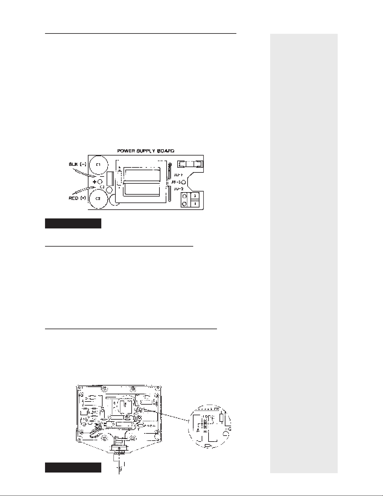
4. INTEGRAL POWER SUPPLY
(P/N 496309 OR OPTION G115)
If your gauge is already equipped with the 12 VDC power supply
(Option G115), the wiring is done as follows:
1. Remove the power supply cover and install strain relief.
2. Connect the 115 or 230 VAC power supply leads to Terminals 1
and 2 on the terminals 1 and 2 on the terminal block at the end of
the power supply printed circuit board and feed these through the
strain relief. (See Fig. 6)
3. If the gauge is equipped with an alarm, attach the appropriate leads
to the five terminals on the terminal strip on the gauge printed
circuit board and feed these through the strain relief.
4. Replace the power supply cover and adjust the wires for service
loop. (See Fig.8).
If you are adding a power supply to an existing gauge, the wiring is
done as follows:
1. Remove from the gauge body the plate holding the strain relief
assembly by removing four screws. Detach the two 12 VDC leads
going to the terminals on the short terminal block on the gauge
printed circuit board and remove them from the strain relief
assembly. 2. Remove power supply cover from base and install
strain relief.
3. Attach the power supply base to the gauge body using the four
tapped inserts and the four screws supplied.
4. Install a black (-) wire from the power supply assembly to Terminal
1 on the short terminal block on the gauge printed circuit board.
Install a red (+) wire from the power supply board to Terminal 2
on the gauge printed circuit board. (Figs. 8 & 9)
5. If the gauge is equipped with an alarm, attach the appropriate leads
to the five terminals on the terminal strip on the gauge printed
circuit board and feed these through the strain relief.
6. Connect the 115 or 230 VAC power supply leads to Terminal 1
and 2 on the terminal block at the end of the power supply
printed circuit board and feed these through the strain relief. (Figs.
8 & 9)
7. Replace the power supply cover, adjust the wire for service loop.
(Fig. 8)
8. Replacement fuse Dynisco P/N 927017, Littlefuse P/N 217.063
or equivalent.

DYNISCO PG500 Series
88
88
8
88
88
8
5. REMOVAL
Because the gauge incorporates a sensitive lower sensing diaphragm,
removal of the instrument from the mounting hole should be
attempted only with the extruder barrel hot. Failure to do could
cause damage due to frozen polymer in the mounting hole adhering
to the diaphragm.
6. CLEANING
Once the unit is removed from the mounting hole, the stem can be
wiped clean with a dry cloth. *Do not attempt to clean the sensing
diaphragm with a wire brush, screwdriver, etc.
7. WARRANTY AND SERVICE
This equipment is sold subject to the mutual agreement that it is free
from defects of material and construction. Our liability in connection
with it shall be limited to the replacement or repair, without charge at
our factory, of any material or construction defect that becomes
apparent within two years from the date that the products are
shipped. We are not liable for damages of any kind arising from the
installation or use of our products or both.
Damaged transducers should be returned to:
DYNISCO INSTRUMENTS
38 Forge Parkway
Franklin, MA 02038
Attn: Repair Dept. RA #__________________
Please call for a Return Authorization Number
before returning product to Dynisco.
Questions concerning warranty, repair cost, and delivery should be
directed to the Dynisco Repair Department, telephone number 508-
ForFor
ForFor
For
technicaltechnical
technicaltechnical
technical
assistance,assistance,
assistance,
call:call:
call:call:
call:
800-221-2201800-221-2201
800-221-2201800-221-2201
800-221-2201

DYNISCO PG500 Series
PG500 Series Manual P/N 974030
12/01 Rev. C
ECO #26292
DYNISCO INSTRUMENTS
38 Forge Parkway
Franklin, MA 02038
Tel.: 508-541-9400
Fax: 508-541-9436
This manual suits for next models
5
Table of contents
Other Dynisco Measuring Instrument manuals