manuals.online logo
Brands
  1. Home
  2. •
  3. Brands
  4. •
  5. E.C.A.
  6. •
  7. Boiler
  8. •
  9. E.C.A. GeliosPlus 11 Operation instructions

E.C.A. GeliosPlus 11 Operation instructions

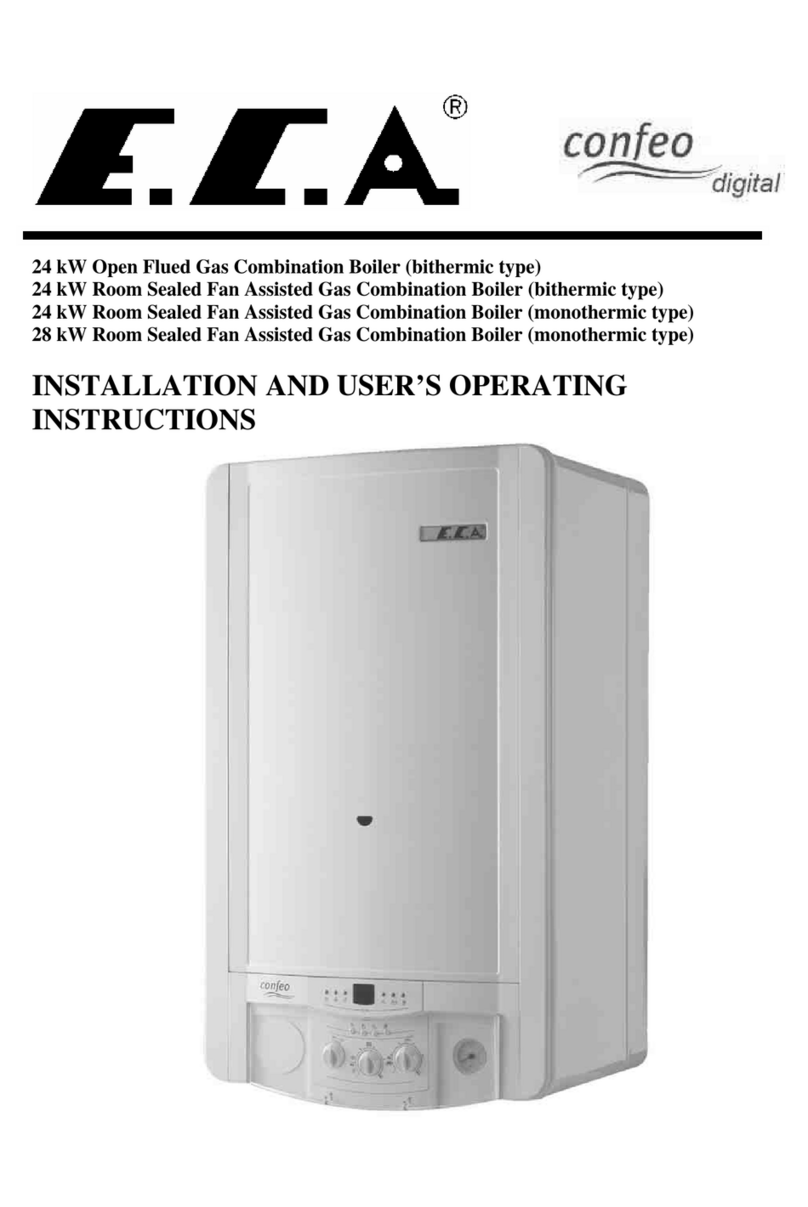
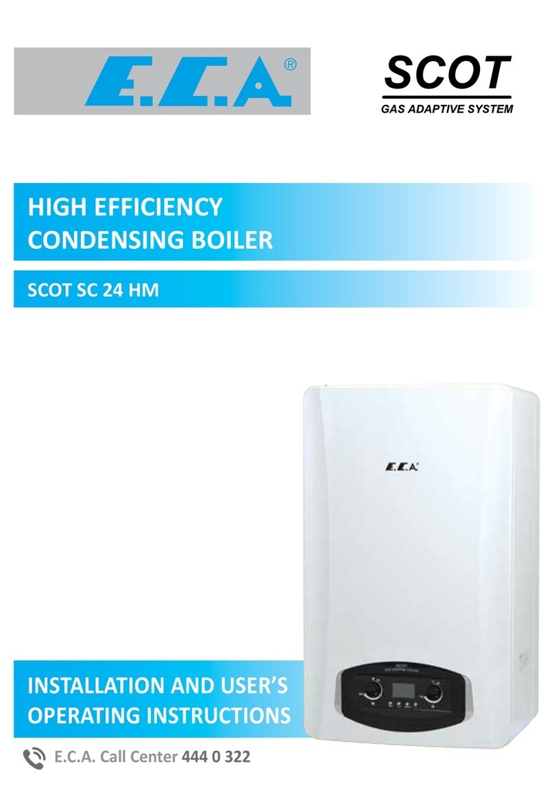
GELIOS PLUS 11/13/16/20/24/28 HM
HERMETIC MONOTERMIC COMBI BOILER
INSTALLATION AND USER’S
OPERATING INSTRUCTIONS
GeliosPl
30
11
10
18
18
19
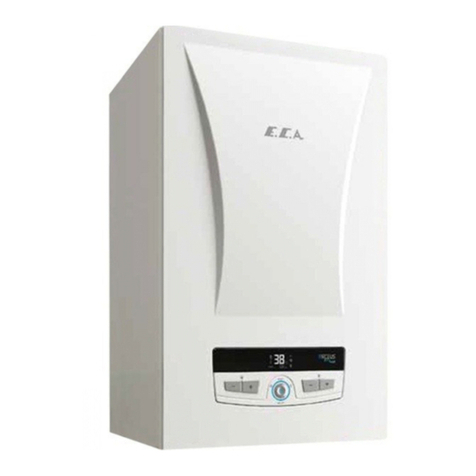
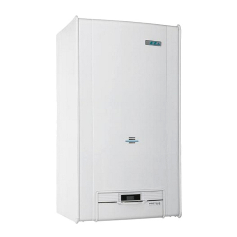
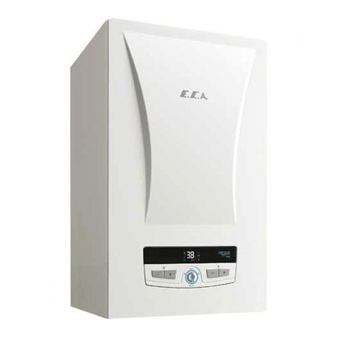
E.C.A. GELIOS PLUS 11/13/16/20/24/28 kW hermetic combi boilers have been designed for
efficient, safe and comfortable central heating and domestic hot water requirement.
Detailed explanations regarding technical features of the device, selection of the point of assembly,
making the connections (water, gas, flue and electric), maintenance information, determination of
possible malfunctions and troubleshooting have been provided in the guide.
Please carefully read the guide in order to benefit from ali the features of your device and to use it
for a long term without any problems.
Keep all the documents provided by your device in order to refer when required.
• AII repairs and annual maintenances should be performed by E.C.A. authorized services. Your
device has 2 years' E.C.A. service warranty against all kinds of malfunctions that may arise from
material and workmanship provided that it is conformed to instructions and warnings being
specified in the assembly and usage guide.
• For the guarantee to be valid, you have to have the date of purchase recorded on the warranty
certificate provided by the guide and approved by the place from where you buy the device.
• This E.C.A. product doesn't require repair under normal conditions of use. But in case you need
help on any issue, EMAR -the after sales customer services of E.C.A. being available in the whole
country- is always at your service.
• The list covering the addresses of our authorized services has been provided additionally.
• The lifetime determined and declared by Ministry of Customs and Trade for the combi boiler
devices is 15 years.
• it is in conformity with the EEE regulation.
2
This appliance can be used by children aged from 8 years and above and persons with reduced physical,
sensory or mental capabilities or lack of experience and knowledge if they have been given supervision
or instruction concerning use of the appliance in a safe way and understand the hazards involved
Children shall not play with the appliance
Cleaning and user maintenance shall not be made by children without supervision
The device is consist of sheet metals which have sharp edges that mayg cause injuries. Service operation
must be done by only authorized people. Proper personel protective equipments must be used during
service operations.
Call your qualified person as soon as possible.
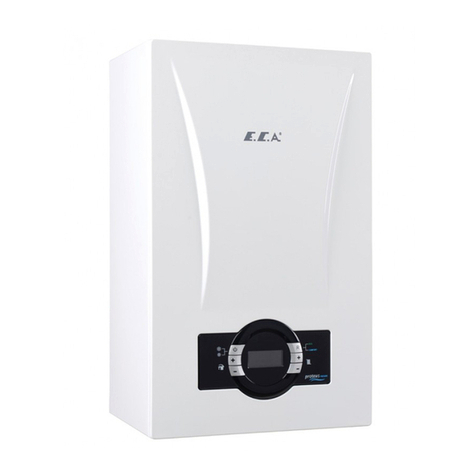
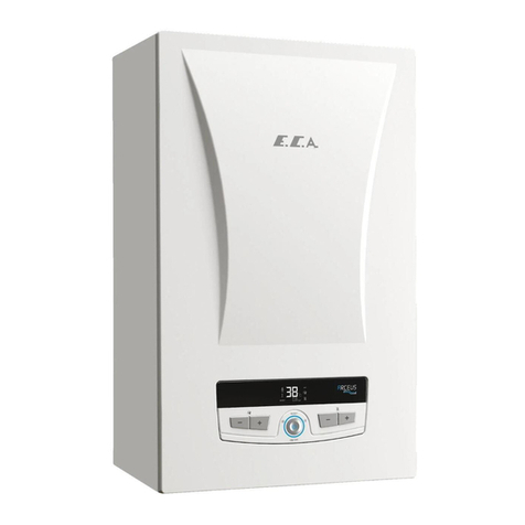
E.C.A. GELIOS PLUS 11/13/16/20/24/28 kW hermetic combi boilers is far central heating and
domestic hot water usage.
It enables saving of place by its design that provides ease of service and maintenance and by its size
of 720x400x330. it has a delicate appearance with its round lines and design.
lts control panel has been designed in an ergonomic structure. lts operation functions,
central heating circuit and running water temperatures, malfunction status, setting values, water
pressure information and current values may be seen over the LCD.
The operation functions and security of the device is ensured over a single center, the 'main board'.
The main board controls the gas valve, fan, circulation pump and 3 way valve. Whether there exists
flame in burner may be monitored from the sightglass on the front panel or from the LCD display .
The burner has been built from stainless steel material that is resistant to temperature and thermal
stress. it operated silent with its special design, and it ensures an efficient and clean combustion as
the result of homogenous distribution of gas. in accordance with the burner, a combustion chamber
with perfect isolation enabling high efficiency and low gas emission with minimum heat loss has
been designed. Due to these features of the burner and combustion chamber, fuel saving is
ensured, and alsa minimum noise level is obtained.
The circulation pump has automatic air relief cock and three cycles, and it is suitable far all the
installations The device has 'pump over-run' feature that prevents thermal accumulation in the
installation. After ending of central heating and/or domestic hat water requirement, the circulation
pump continues to operate far a specific period by this feature.
High efficiency is obtained by durable copper exchanger that has been designed to prevent thermal
shock. Moreover, there is a separate exchanger with steel plate within the device in order to obtain
comfartable and efficient domestic hot water.
By the safety systems on your device, the full safety of your device and you has been ensured. These
safety systems;
• Flame Out Safety
• Excessive Temperature Safety (105°C)
• Running Water Excessive Heating Safety (71°C)
• Central Heating Circuit Water Excessive Heating Safety (95°C)
• High Water Pressure Safety (3 bar)
• Low Water Pressure Safety (0.8 bar)
• Low Voltage Safety (155VAC)
• Hot Water Accumulation Safety (additional operation of by-pass circuit and pump)
• Freeze Safety
(the electrical connection of the device shouldn't be cut far the operation of freeze
safety)
• Pump Jamming Safety
• 3 Way Valve Jamming Safety
• Automatic Air Relief Cock
• Expansion Tank
GELIOS PLUS hermetic
119
IPx4D
6
GELIOS PLUS 11, 13, 16, 20, 24, HM
I
2H
90.6
12,814,817,922,325,6
1,38 1,58 1,93 2,41 2,76
11,3
32
GELIOS PLUS 11/13/16/20/24/28 HM
E.C.A. GELIOS PLUS 11/13/16/20/24/28 kW Hermetic Combi Boiler (monothermic model)
**
30-80
* : If the twin chimney outlet is not available as shown in Figure 14, a twin chimney adapter should be used to install
these chimney types.
28 HM
90.7
9,5
28
10,5
30,5
3,22
1,12
12(
8
2
=33,4)
33
2
1- ROOM THERMOSTAT (Opt.)
2- GAS VALVE MODULATOR
3- CH TEMPERATURE SENSOR
4- WATER PRESSURE SENSOR
5- LIMIT THERMOSTAT
6- AIR PRESSURE SWITCH
7- DHW TEMPERATURE SENSOR
8- TURBINE
9- OUTSIDE TEMP. (Optional)
10- PUMP
11- FAN
12- GAS VALVE
13- SUPPLY CABLE
14- 3 WAY VALVE
15- POTENTIOMETER DHW TEMP.
16- POTENTIOMETER CH. TEMP.
17- ON / OFF / RESET / SUMMER / WINTER MODE
18- FUSE
19- LCD DISPLAY
20- FAILURE LED
21- IGNITION AND IONISATION ELECTRODE

PACKAGING
CAUTION: 



Figure 2




 


 
ASSEMBLY
Determination of the Location where the Device will be Assembled




 


°

       




  
  

J
Figure 3



DANGEROUS: 


7
Min distancetothe roof
Human area
Vehicle area
POSITION DISTANCE (cm) POSITION DISTANCE (cm)
A-Below a windows
60
G- Next to vertical or horizontal pipe
60
B- Below an air vent
60
H- Below the distance grille from the outside
30
of the building
C- Below rain channel
30
I- Distance from the inner corner of the
100
buildina
D- Under the balcony
30
L- From the ground or from the fioor
180
E- Next to a window
40
M- Vertical distance of two fiue outlets
250
F- Next to an air grill
60
N- Horizontal distance of two fiue outlets
100
Figure 4b
Figure 4a
9
•In C type devices, the horizontal outlets should be assembled by a 1-2% downward inclination at
the outside for rain water etc. not to enter inside the device (Figure 5a).
•The distance of waste gas outlet with the opposite building should be at least 3 m. in
the direction of discharge of waste gas (Figure 5b).
•There should be at least 2.5 m. upwards distance in between the flue outlets of C type devices.
Moreover, the waste gas outlets of these devices should be 30 cm. below the bottom edge of
the window (Figure 5c).
•"C" type devices below the ground level (at basements) can only be installed if the combustion
air and was gas pipe lines of each device are opening to their own channels. The cross-section
areas of the channels should be at least 0.75 m2 and the small edge size of the channel should be
at least 0.5 m. There shouldn't be vents or windows opening to these channels.
•In C type devices, combustion air and waste gas pipe outlets should be at least at 5 m. horizontal
distance from the fuel pumps and fuel tanks.
a) c)
min.2,Sm
b}
Figure 5
10


 
     




















1. Horizontal flue connection (ø 60 /100 mm ) up to max. 4 meters
2. Vertical flue connection (ø 60 /100 mm ) up to max. 4 meters
3. Twin flue connection (ø 80/80 mm ) up to max. 8 meters
for 28 kW
1. 5 meters
2. 6 meters
3. 12 meters
(for 28 kW 5m)
(for 28 kW 4m)
(for 28 kW 4m)
5
12
13
Connection of Horizontal (060/lOOmm) Hermetic Flue Set to the Combi Boiler
As your combi boiler is hermetic model, it takes the air used from the external environment, and
discharges the waste gases arising as the result of combustion from the same flue group. The use
and assembly of flue is very important for the extremely harmful waste gases not to be spread in
the environment, thus the warnings should be considered while making the flue connections.
Horizontal outlets should be assembled with 1-2% downwards inclination for
rain water etc. not to enter the device. (Figure Sa)
Horizontal (Ø60/100 mm ) Hermetic Flue Set Consists of the Following Parts;
1. Flange gasket
2. Flue connection flange
3. Flange screws
4. Sealing gasket
5. 90 ° bend
6. Clamp
7. Clamp screws
8. EPDM connection gasket
9. Flue outlet terminal
10. Interior wall connection flange
11. Exterior wall connection flange(EPDM)
Figure 8
•Make the required flue selection for the flue connection to be made to outer environment from
the location where your combi boiler is assembled. If the standard flue set is insufficient, select
the most suitable accessories from our connection accessories list considering the warnings
referred in our guide.
•Fix the flue connection flange through screwing to the holes on the combi boiler by using the
flange gasket. (Figure 9a-9b)
•Place the 2 sealing gaskets -provided by the hermetic flue set- to interior pipe slots on both ends
ofthe bend of 90 °.
•Apply the EPDM connection gasket to the bend of 90 ° as to contact the limiting set inside the
gasket.
•In order to group the flue outlet terminal, apply the exterior wall (EPDM) gasket to flue terminal
as seen in Figure 9c. After passing the flue outlet terminal through the exterior side of the wall
and from the previously opened hole, connect the interior wall connection gasket to flue
terminal. Apply the other end of the EPDM connection gasket of your combi boiler -which is
applied to flue bend of 90 °-to the flue outlet terminal, and apply the clamp on the EPDM
connection gasket and loosely tighten it with screw (Figure 9d). And then place the bend of 90 °
on the flue connection flange, and fix with tightening screws (Figure 9e). Finally, after tightening
the screws which are placed on EPDM gasket and which are left loose, enable the flue and wall
tightness by pushing the interior wall connection gasket as to touch the wall.
Figure 9a Figure 9b
Figure 9c
Figure 9e
Issues to be Considered in Flue Connection Extensions
In case the hermetic flue set -provided by the packaging of the product- is of insufficient length,
additional hermetic flue accessories should be ordered from an authorized E.C.A. vendor as per
requirement, and other hermetic flue accessories should not be used.
• (Ø60/lOOmm) Hermetic Flue Set Accessories (Figure-10)
a) Extension pipe (500 mm), EPDM gasket, clamp and clamp screws
Extension pipe (1000 mm), EPDM gasket, clamp and clamp screws (Figure - 10a)
b) Bend of 90° , EPDM gasket, clamp and clamp screws (Figure-10b}
a) b)
Figure 10
c)
14
Restrict
or Fan
43
GELIOS PLUS
24 , 20 kW
39
GELIOS PLUS
16 , 13 , 11 kW
43
GELIOS PLUS
28 kW 4 < 5
5
47
47
4
47
47
15
16
3) 6)
7)
1)
2)
4)
5)
43
GELIOS PLUS
24 , 20 kW
17
39
GELIOS PLUS
16, 13, 11 kW
5
4
3
4 < 5
5
4
3
4 < 5
18
L3
L1
L2
L2
L1
Lmaks= 4m Ø60/100
(for 28 kW 6m)
4m 3m
5m
(for 28 kW 5m) (for 28 kW 4m)
43
GELIOS PLUS
28 kW
6
5
4
4 < 5
5 < 6
4 < 5
47
47
47
47
47

This manual suits for next models

5

Other E.C.A. Boiler manuals

E.C.A. Proteus Plus Blue 24 kW User manual

E.C.A.

E.C.A. Proteus Plus Blue 24 kW User manual

E.C.A. Fortius User manual

E.C.A.

E.C.A. Fortius User manual

E.C.A. ARCEUS EK 12 MT ERP UK Operating manual

E.C.A.

E.C.A. ARCEUS EK 12 MT ERP UK Operating manual

E.C.A. FELIS Series User manual

E.C.A.

E.C.A. FELIS Series User manual

E.C.A. ARCEUS EC 6 kW MT User manual

E.C.A.

E.C.A. ARCEUS EC 6 kW MT User manual

E.C.A. GP11 User manual

E.C.A.

E.C.A. GP11 User manual

E.C.A. Confeo Premix Operation instructions

E.C.A.

E.C.A. Confeo Premix Operation instructions

E.C.A. PROTEUS PREMIX 14 HM NG ERP UK User manual

E.C.A.

E.C.A. PROTEUS PREMIX 14 HM NG ERP UK User manual

E.C.A. ARCEUS 12 MT Operating manual

E.C.A.

E.C.A. ARCEUS 12 MT Operating manual

E.C.A. Proteus Plus Operation instructions

E.C.A.

E.C.A. Proteus Plus Operation instructions

E.C.A. SCOT SC 24 HM User manual

E.C.A.

E.C.A. SCOT SC 24 HM User manual

E.C.A. KRONOS KR 24 HM User manual

E.C.A.

E.C.A. KRONOS KR 24 HM User manual

E.C.A. ARCEUS 6 kW MT User manual

E.C.A.

E.C.A. ARCEUS 6 kW MT User manual

E.C.A. PROTEUS PREMIX 14 HM NG ERP UK User manual

E.C.A.

E.C.A. PROTEUS PREMIX 14 HM NG ERP UK User manual

E.C.A. CO 24 BB Operation instructions
E.C.A.

E.C.A. CO 24 BB Operation instructions

E.C.A. CA 24 BB Operation instructions

E.C.A.

E.C.A. CA 24 BB Operation instructions

E.C.A. Confeo Premix CP 24 HST Operation instructions

E.C.A.

E.C.A. Confeo Premix CP 24 HST Operation instructions

E.C.A. Proteus Premix Series Operation instructions
E.C.A.

E.C.A. Proteus Premix Series Operation instructions

Popular Boiler manuals by other brands
Vortice VORT HR 300 NETI installation guide

Vortice

Vortice VORT HR 300 NETI installation guide

Viessmann VITODENS 050-W installation instructions

Viessmann

Viessmann VITODENS 050-W installation instructions

Potterton NXR4 Installation, operation & maintenance manual

Potterton

Potterton NXR4 Installation, operation & maintenance manual

British Gas RD5 user guide

British Gas

British Gas RD5 user guide

Vaillant ecoCRAFT exclusive VKK GB 1206/3-E R1 Installation and maintenance instructions
Vaillant

Vaillant ecoCRAFT exclusive VKK GB 1206/3-E R1 Installation and maintenance instructions

Sonnenkraft PSC-E Series manual

Sonnenkraft

Sonnenkraft PSC-E Series manual

THERMOSTAHL EBS 24 user manual

THERMOSTAHL

THERMOSTAHL EBS 24 user manual

Fracino ATKANTIS Installation & user manual

Fracino

Fracino ATKANTIS Installation & user manual

clage Zip Hydroboil Plus Series Operating and installation instructions

clage

clage Zip Hydroboil Plus Series Operating and installation instructions

NISBETS ESSENTIALS DF524 instruction manual

NISBETS ESSENTIALS

NISBETS ESSENTIALS DF524 instruction manual

U.S. Boiler Company MPO-IQ Installation, operating and service instructions

U.S. Boiler Company

U.S. Boiler Company MPO-IQ Installation, operating and service instructions

Sussman SVS Series Installation, operation and maintenance manual
Sussman

Sussman SVS Series Installation, operation and maintenance manual

Ferroli Optima 900 instructions

Ferroli

Ferroli Optima 900 instructions

Potterton Powermax HE 85 User instructions

Potterton

Potterton Powermax HE 85 User instructions

ECR PENNCO 15B Series Installation, operation & maintenance manual

ECR

ECR PENNCO 15B Series Installation, operation & maintenance manual

Ferroli DOMIcompact F 30 B Instructions for use, installation and maintenance

Ferroli

Ferroli DOMIcompact F 30 B Instructions for use, installation and maintenance

Mareli Systems CB 25 Assembly and exploitation manual

Mareli Systems

Mareli Systems CB 25 Assembly and exploitation manual

REMEHA Selecta technical information

REMEHA

REMEHA Selecta technical information

manuals.online logo
manuals.online logoBrands
  • About & Mission
  • Contact us
  • Privacy Policy
  • Terms and Conditions

Copyright 2025 Manuals.Online. All Rights Reserved.