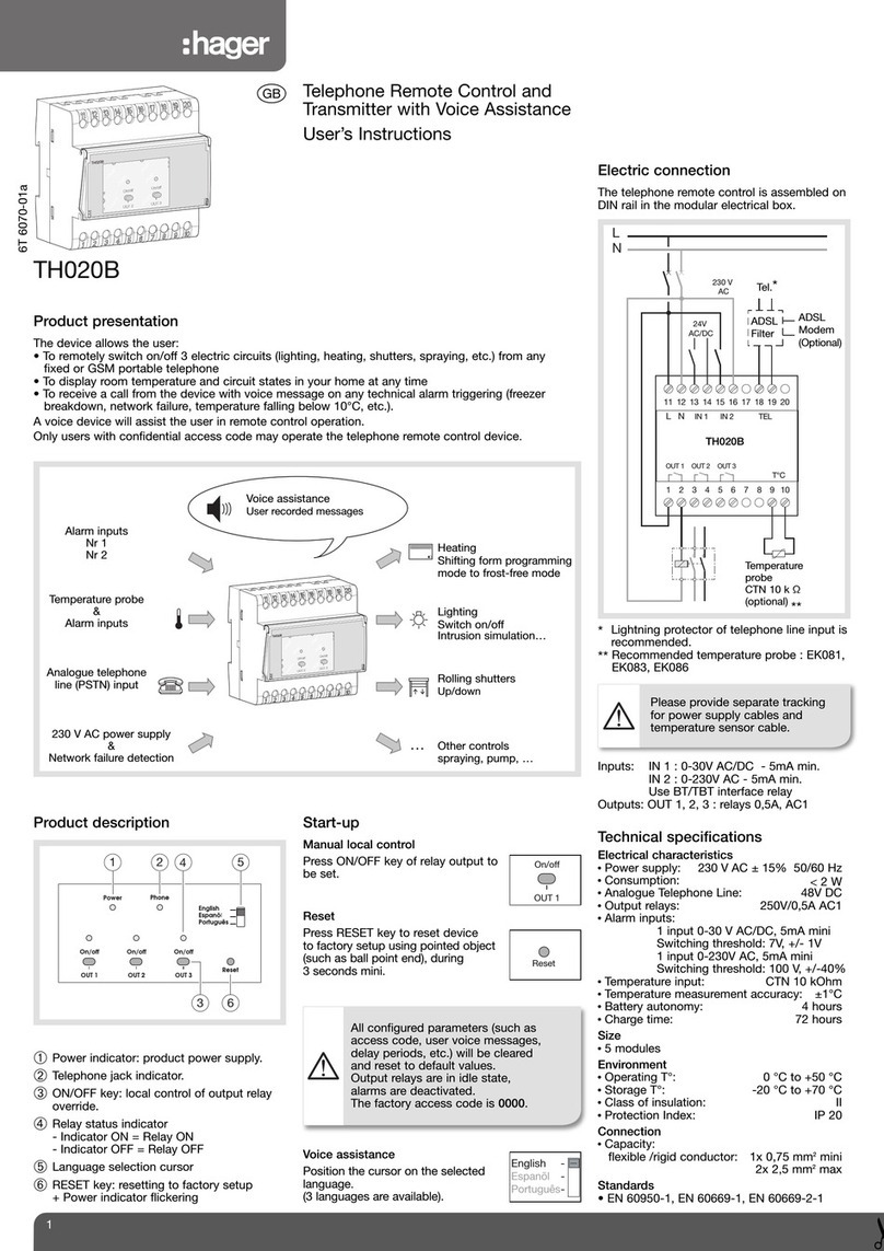
E.F. Johnson Ranger User manual

i '
'\.I
'
OPERATIIG
MA"UAL
VIKING
RA
:NGER
TRANSMITTERLEXCITER

Built-in
VFO-TVI
Suppressed
75
Watts
CW
Input-65
Watts
phone
Input
Instant
Bandswitching
-7
Amateur
Bands

RANCER
Effectively
TVI
suppressed, and
completely
self-contained,
the
Viking
"Ranger"
transmitter/exciter
kit
is
designed
for
easy
assembly
by
either
novice
or
experienced
amateur.
A
phone
and
CW
transmitter
on
the
10
through
160
meter
amateur
bands, the
"Ranger"
may also
be
used
as
a
flexible
exciter
without
modification.
As
a transmitter, the
"Ranger"
is
a
rugged
and
compact
75
watt
CW
input
or
65
watt
phone
unit.
100%
AM
modulated,
the
"Ranger"
has a
pi-network
coupling
system
that
will
match antenna
loads
from
SO
to
SOO
ohms.
Covering
seven
amateur
bands,
160,80,40,20,
15,
11
and
10
meters-built-in
VFO
or
crystal
control
features
high
gain
audio
within
the
communications speech range.
As an
exciter,
the
"Ranger"
will
drive
any
of
the
popular
kilowatt
level
tubes and
will
provide
a high
quality
speech
driver
system
for
high
powered
modulators
. The
"Ranger's"
design permits basic
control
functions
for
the high
power
stage
to
be
handled
right
at
the
exciter-no
modification
or
internal
change
required
to
shift
from
transmitter
to
'
exciter
operation
with
all
connecting
leads
TVlfiltered
inside the
"Ranger"
cabinet.
TRANSMITTER
/
EXCITER
KIT
A nine pin
receptacle
on the
rear
of
the
transmitter
brings
out
TVI
filtered
control
and
audio
leads
for
exciter
operation.
This
receptacle
also
permits the
"Ranger"
to
be
used
as
a
filament and
plate
"power
source and also
as
a
modulator
for
operating
auxiliary
equipment
such
as
a VHF transmitter.
Available
at
the
output
receptacle
are
6.3 V
AC
at
5.5 Amp.,
500 V
DC
at
up
to
210
MA
and 300 V
DC
at
up
to
SO
MA
along
with
the full 33
watts
output
of
the
modulator.
BUILT-IN
VFO-
The built-in
VFO,
patterned
after
the famous
Johnson
Model
122,
is
extremely
stable.
Separate
calibrated
bandspread
dial
scales
for
each
of
the seven bands and a
new
6
to
1
planetary
dial
mechanism using a
2Ya"
diameter
knob result
in
exceptional
tuning
accuracy
with
velve
t smooth
control.
The 28.0
to
29.7
MC
calibration
alone
is
nine inches
long
and
14
.0
to
14.35
MC
covers
more
than
three
inches on
the
dial.
For permanent accuracy, di
al
pointer
is
connected
directly
to
the
frequency
determining
VFO
element. Plexiglass
dial
is
edge
lighted;
ruled Plexiglass
pointer
rides close
against
dial
on metal
bearing
to
insure a minimum
of
parallax.
Precise
10
kc
calibration
increments
on
each band
provide
l!niform and
accurate
dial
interpretation.
KEYING-
Excellent
break-in
keying
characteristic,
a special
design aim
in
the
"Ranger,"
is
achieved
by
light
loading,
voltage
regulation
and
careful
circuit
design.
Easy
to
tune, the
"Ranger's"
basic tuning
controls
are
located
on the VFO Dial escutcheon.
QSY
within the
phone
or
CW
portion
of
a band
is
usually possible
by
merely
changing
the VFO
frequency
setting. For
larger
frequency
excursions,
simply touch up the
grid
{Buffer! tuning, adjust
loading,
and
dip
the final. Simple
as
ABC.
Other
controls,
used
for
initial
tuning, changing bands
or
changing
mode
of
transmis-
sionare
as
follows:
Off-
Tune-Phone-Standby-CW
switch,
Bandswitch, Crystal 1-Crystal 2-VFO-VFO
Zero
switch,
Meter
Off-Osc.-Buffer-Grid-Plate-Mod
. switch,
Audio
Gain,
RF
Drive,
Coupling
and
Auxiliary
Coupling
. The VFO
frequency
control,
Final Plate tuning and Buffer tuning dials
are
located
on
the
VFO
dial
escutcheon.
TVI SHIELDING
AND
FILTERING-Completely
TVI Sup-
pressed, the
"Ranger"
cabinet
is
sealed
electrically,
using
flexible
monel
braid
on the inside
of
the
front
panel and
large
cabinet
overlap.
A cup
type
shield seals the meter,
and spring
contact
washers on the
front
panel shafts
prevent
possible
radiation
from
shaft
clearance
openings.
Power
line and
relay
jack have
double
l
type
filters, and all
auxiliary
socker, meter,
dial
lamp, key, meter, and meter
lamp leads have l
filter
networks.
To
minimize chassis
har-
monics,
interior
harness leads and filaments
are
by-passed.
Careful
final by-passing plus special
circuit
techniques minimize
harmonics in the
output
circuit.
GENERAL
SPECIFICATIONS
VFO-EXCITER-
The
front
panel bandswitch, switches
all
stages from the
VFO
through the final
amplifier.
The series-
tuned
Colpitts
VFO circuit, with
temperature
compensation
and
voltage
regulation,
is
designed
to
operate
very
lightly
loaded
for
maximum stability.
The crystal
oscillator
/VFO
isolator
stage (6Cl6J has
broad
tuned
plate
circuits
to
eliminate
need
for
a
separate
tuning
control.
The buffer (6Cl6J
plate
circuit tunes
to
the
operating

l Shielded Meter
-----,H
J.~-·'II=II!!!=;====I~
TVI
Filters
TVI
Filters
----.
P:'
~---Shielded
Built-In
VFO
l
-----
"function" Switch
1 High
"Q"
Pi-Netw---,-or...;.k
__
-+~
Output
Coil
1
Coaxial
Output
Connector
Key
Jack
-----..J
::::;J
----
Relay Jack
1 Microphone
Jack
____
l~i~.ilg
••
1!l1l1i
-r=;:;...---
Plug-for exciter
operation
1 Fused
line
Plug
----'-----
1
frequency
at
all
times, maintaining a
relatively
high
C/l
ratio
to
insure
good
harmonic and subharmonic
rejection.
A sep-
arate
front
panel
drive
control
allows
precise
drive
adjust-
ment
for
optimum
amplifier
performance.
1 FINAL
AMPLIFIER-An
efficient
pi-network
tonk
circuit
is
designed
to
handle 50
to
500 ohm resistive antenna
loads
and
is
capable
of
tuning
out
large
amounts
of
reactance.
Plate
circuit
capacitor
switching
provides
the best
combination
1
of
variable
and
podding
capacity
for
ease
of
tuning
and
proper
loading.
Final
amplifier
tube
is
a 6146.
SPEECH-MODULATOR
SECTION-A
three
stage
triode
speech amplifier,
with
inverse feedback,
provides
exception-
J
".....
ally
flat
response and stable,
low
impedance
drive
to
the
110dulators. The first
two
amplifier
stages consist
of
cascade
connected
triode
sections
of
a 12AX7
working
into
a
parallel
connected
12AU7
power
driver.
Extra high speech
gain
permits the
use
of
virtually
any
communications
type
dynamic
]
or
crystal
microphone.
A
three
circuit
microphone
connector
is
provided
to
facilitate
connection,
i.f
desired,
for
push-to-
talk
operation.
Push-pull 1614 transmitting type
modulators
operate
within
J tube ratings
to
deliver
more than sufficient
audio
power
for
100%
amplitude
modulation.
Plate saturation limiting pr,e-
vents
large
swings
beyond
full
modulation,
at
the some time
providing
some limiting
of
the
waveform
to
reduce
distortion
and spurious
output
if
transmitter
is
over-modulated
.
A special
feedback
loop,
using a
tertiary
winding on the
modulation
transformer,
provides
damping
for
exceptional
stability
and
flat
response
in
the speech stages and
provides
improved
regulation
for
directly
driving
closs
B2
modulators
when the
"Ranger"
is
used
as
on
exciter
. Frequency response
is
flat
within
3db
from 250
to
3000 cycles and falls
off
rapidly
above
and
below
these frequencies.
Audio
quality
is
very
pleasing
yet
has
the
extra
audio
punch
needed
for
com-
munications effectiveness.
or
auxiliary
power
ClAMPER-
The
clamper
circuit, using a
pentode
connected
6AQ5,
protects
the final tube in case
of
excitation
failure,
yet
allows
full
modulation
swings
without
danger
of
peak
distortion.
POWER
SUPPLY
AND
CONTROL-Self-contained
low
volt-
age
and high
voltage
power
supplies
use
choke input
filtering
-high
voltage
supply
delivers
500
to
525V
DC
to
the final
and
modulators-low
voltage
supply delivers300 V
DC
for
th
e
exciter
and
speech stages.
A
separate
relay
jock (with internal TVI fllte'rs
to
prevent
harmonic
radiation
from
connecting
wires)
provides
115 V
AC
for
antenna
change-over
and
control
relays. The
relay
jack
is
energized
by
the
Operate
Switch on the
front
panel.
Transmitter fuse
is
located
in
the 115
volt
power
plug
for
easy access.
Complete
instructions
for
using the
"Ranger"
as
a self-
contained
Transmitter,
as
an Exciter and Speech
Driver,
or
as
a
Power
and
Modulator
source
for
VHF-UHF
transmitter
are
included
in
the instruction manual.
No
internal changes
necessary when switching
from
transmitter
to
exciter
opera-
tion-ail
functions handled
at
standard 9 pin
power
recep-
tacle
and matching plug
at
rear.
Crystal socket,
located
on
front
panel, accommodates
two
crystals and can be switched from
front
panel.
Meter
is
illuminated and meters
all
stages
with
selector
switch.
APPEARANCE-Extremely
sturdy and compact, the
"Ranger"
measures
only
15" x
11-5/16"
x
9".
The
18
gouge steel
cabinet
with
drawn
rounded corners
is
finished in rich
maroon
wrinkle
enamel-with
a smooth maroon and
gray
enameled
front
panel. Entire chassis and
front
panel slides
out
of
cabinet
after
removing just
two
knurled
tie
bolts
and 8
shield 'retaining screws.
When
removed, topside and
under-
chassis
are
completely
accessible.
Guide
rails insure easy
reinsertion
of
the chassis
into
,cabinet.
ASSEMBLY-Designed
as
a
complete
kit, the
"Ranger"
may
be
assembled
by
either
novice
or
experienced
amateur. Assembly instructions include
photographs,
diagrams
and step-by-step
wiring
directions.
All
information
needed
including tube socket
diagrams and
component
color
coding
is
furnished
with
the kit -
no
outside source
of
information
required.
Chassis, panel,
cabinet
and all shields
are
formed and
punched
at
the
factory.
No
drilling
or
other
metal
work
is
necessary.
Complete
to
the
last detail, the
"Ranger"
kit includes
cabinet,
knobs, dials,
pre-calibrated
VFO
dial,
/""
'Vi
ring harness,
hardware,
brackets, connectors, and all necessary
electrical
compon-
ents.
Complete
operating
instructions included. Shipping
weight
approximately
54 Ibs.
$179
50
Cat. No.
240-161
"Viking
Ranger" Kit, less tubes
........
..
...
.
..
.
..
.
.......
.
Cat. No.
240-161-2,
"Viking
Ranger';
wired
and tested.
$258.00
Amateur
Net.
AMATEUR
NET

CRYSTAL
CHART,
BLOCK,
AND
SCHEMATIC
DIAGRAMS
6146
Crystal Bands
6AU6
6el6
6el6
p,
CRYSTAL
NETwORK
160
meter
160
osc.
V,O
BUfFER
rlNA.1,.
80
AMP.
80
meter
80
40
40
meter
40
20
~12AX7
15
F"iR5T
SPEECH
AMP.
10
6.5
Mc.
11
TO ALL
LOW
Chart
shows crystals
which
may
POWER
STAGE.S
be
used
full
output on the
ama-
F'IL.L3v
teur
bands
covered
by
the TO
AUDIO
FILAMENTS
"Ranger."
-
E.
F.
JOHNSON
COMPANY
•
WASECA,
MINNESOTA
Form
724K054
Catalog No.
724
Printed
in
U.
S. A.
This manual suits for next models
1
Table of contents
Popular Transmitter manuals by other brands

Evikon
Evikon PluraSens E2648-CO2 user manual
Endress+Hauser
Endress+Hauser Proline 500 digital PROFIBUS DP Brief operating instructions
Emerson
Emerson Rosemount 5408 Reference manual

BWI Eagle
BWI Eagle AIR-EAGLE SR PLUS 36-HH-9 quick start guide

Kannad
Kannad SafeLink AIS SART2 user manual

Rosemount
Rosemount FISHER-ROSEMOUNT 244EH product manual
