manuals.online logo
Brands
  1. Home
  2. •
  3. Brands
  4. •
  5. INOR
  6. •
  7. Transmitter
  8. •
  9. INOR IPAQ CT20 User manual

INOR IPAQ CT20 User manual

MEASURE OF SUCCESS
USER INSTRUCTIONS
Compact, PC-programmable
2-wire Transmitter with
integrated M12 connectors
for Pt100 Input
The user instruction must be read prior to adjustment and/or installation.
All information subject to change without notice.
1000311506 - 2015-10
GENERAL INFORMATION
IPAQ CT20 is a compact, analog, non-isolated, 2-wire temperature
transmitter for Pt100 3W input with a temperature linear 4-20 mA
output signal. The transmitter has integrated M12 connectors for both
input and output connections.
The transmitter is congured from a PC via a USB port, connected via
the INOR USB Interface, by using the ConSoft conguration program.
All necessary hardware and software for conguration are included
in the ICON conguration kit, except the M12 adapter cable USB
Interface that must be ordered separately.
Inor offers a wide range of sensors for connection to the compact
transmitter.
CT20
MEASURE OF SUCCESS
This product should not be mixed with other kind of scrap, after usage.
It should be handled as an electronic/electric device.
www.inor.com, www.inor.se
DATA (shortform)
CONFIGURATION
Installation of software and driver
Before making a conguration of IPAQ CT20 you need to do following:
1. Install ConSoft 3 or higher and drivers for the USB Interface.
2. Connect the USB Interface to a free USB port of your PC and
wait for automatic installation of the USB Interface.
Please refer to “Quick Installation Guide for ConSoft 3” for
installation instructions.
Conguration procedure:
1. Connect the output M12 connector on IPAQ CT20 to the PC via
the M12 adapter cable and USB Interface, LED indicator “DEV”
on the USB Interface becomes green. (The transmitter is
powered from the USB interface during conguration so no
external power supply is needed)
2. In ConSoft 3, click on the “Read” button. The software will
recognize the connected transmitter, upload the transmitter’s
conguration and open the conguration window.
3. In the conguration window you can congure:
a. measuring range
b. measurement unit
c. upscale or downscale action at sensor break
d. input sensor compensation for known sensor errors
e. TAG-number (16 characters)
4. The selected conguration is downloaded to the transmitter by
clicking the “Write” button. When the data transfer is complete,
the transmitter begins using the new parameters directly.
INOR Process AB, PO Box 9125, SE-200 39 Malmö, Sweden,
Phone: +46-40-31 25 60, Fax: +46-40-31 25 70, E-mail: support@inor.se
INOR Transmitter OY, Unikkotie 13, FI-01300 Vantaa, Finland,
Phone:+358-10-421 7900, Fax: +358-10-421 7901, E-mail: jari.stadig@inor.se
INOR Transmitter GmbH, Duissernplatz 15,
47058 Duisburg, Germany,
Phone: +49-(0)203 86055-300, Fax: +49-(0)203 86055-333,
E-mail: [email protected]
KROHNE Temperature Division INOR, 7 Dearborn Road,
Peabody, MA 01960, USA,
Phone: +1-978-826 6900, Fax: +1-978-535 3882, E-mail: inor-inf[email protected]
Input 3-wire Pt100 IEC 60751, α=0.00385
Output Analog, 4-20 mA, temperature linear
Response time (90%) < 10 ms
Measuring range limits -50...+800°C
Zero limits -50°C to +50°C
Minimum span 50°C or 20°C, If the zero point is set at
-40 °C, -20 °C, 0 °C, +20 °C or +40°C the
minimum span is 20 °C, otherwise it is 50 °C.
Sensor break Selectable, Upscale (≥21.0 mA) or
downscale (≤3.6 mA) action
Sensor short-circuit Fixed, downscale (≤3.6 mA) action
Ambient temperature -40 to +85 °C (storage and operation)
Humidity 0 to 100 %RH
General data
Galvanic isolation No
Power supply 7.5 to 32 VDC, polarity protected
Basic accuracy Max. of ±0.2 °C or ±0.2 % of span
Process connection input M12x1, 4-pin, A-coded, Female
Process connection output M12x1, 4-pin, A-coded, Male
INPUT CONNECTIONS
DIMENSIONS
ORDERING INFORMATION
LIMITED WARRANTY
INOR Process AB, or any other afliated company within the Inor Group (hereinafter
jointly referred to as ”Inor”), hereby warrants that the Product will be free from
defects in materials or workmanship for a period of ve (5) years from the date of
delivery (”Limited Warranty”). This Limited Warranty is limited to repair or replace-
ment at Inor’s option and is effective only for the rst end-user of the Product. Upon
receipt of a warranty claim, Inor shall respond within a reasonable time period as to
its decision concerning:
1 Whether Inor acknowledges its responsibility for any asserted defect in
materials or workmanship; and, if so,
2 the appropriate cause of action to be taken (i.e. whether a defective
product should be replaced or repaired by Inor).
This Limited Warranty applies only if the Product:
1 is installed according to the instructions furnished by Inor;
2 is connected to a proper power supply;
3 is not misused or abused; and
4 there is no evidence of tampering, mishandling, neglect, accidental damage,
modication or repair without the approval of Inor or damage done to
the Product by anyone other than Inor.
This Limited Warranty is provided by Inor and contains the only express war-
ranty provided.
INOR SPECIFICALLY DISCLAIMS ANY EXPRESS WARRANTY NOT
PROVIDED HEREIN AND ANY IMPLIED WARRANTY, GUARANTEE
OR REPRESENTATION AS TO SUITABILITY FOR ANY PARTICULAR
PURPOSE, PERFORMANCE, QUALITY AND ABSENCE OF ANY HID-
DEN DEFECTS, AND ANY REMEDY FOR BREACH OF CONTRACT,
WHICH BUT FOR THIS PROVISION, MIGHT ARISE BY IMPLICATION,
OPERATION OF LAW, CUSTOM OF TRADE OR COURSE OF DEALING,
INCLUDING IMPLIED WARRANTIES OF MER-CHANTABILITY AND
FITNESS FOR A PARTICULAR PURPOSE. EXCEPT AS PROVIDED HER-
EIN, INOR FURTHER DISCLAIMS ANY RESPONSIBILITY FOR LOSSES,
EXPENSES, INCONVENIENCES, SPECIAL, DIRECT, SECONDARY OR
CONSEQUENTIAL DAMAGES ARISING FROM OWNERSHIP OR USE
OF THE PRODUCT.
Products that are covered by the Limited Warranty will either be repaired or replaced
at the option of Inor. Customer pays freight to Inor, and Inor will pay the return
freight by post or other “normal” way of transport. If any other type of return freight
is requested, customer pays the whole return cost.
IPAQ CT20 70CT200010
ICON Conguration kit * 70CFGUS001
M12 adapter cable for USB Interface 4004430401
Output connecting cable with 4003211501
angled M12 connector, length 2 m
Output connecting cable with 4003211502
angled M12 connector, length 5 m
* M12 adapter not included in the kit, must be ordered separately
Supply voltage U (V DC)
RLOAD(Ω) =(U-7.5)/0.022
OUTPUT LOAD DIAGRAM
55,5
Ø15
M12x1
M12x1
1
2
4
3
Pt100
-
+
12
43
OUT
RLOAD
CALIBRATION
CONNECTION
Due to the low long-term drift of max ±0.1 % of span per year, a
recalibration of the transmitter is normally not needed. Should you for
any reason require a recalibration, the transmitter must be returned
to the factory.
3. Blue -
4.
1. Brown +
2.
OUTPUT CONNECTIONS
M12 -Female
M12 -Male
InputOutput
mm

Other INOR Transmitter manuals

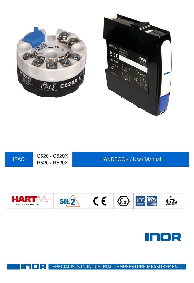
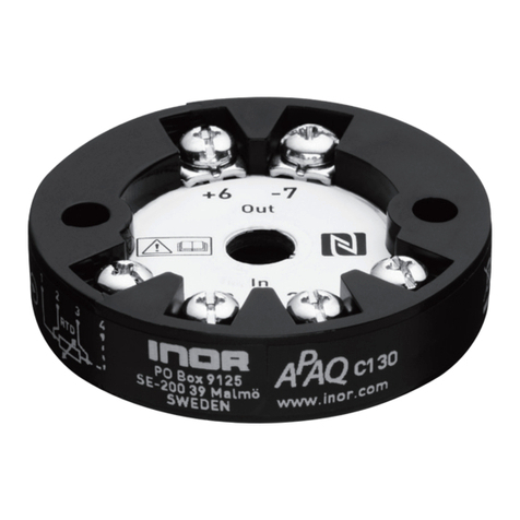
INOR APAQ C130 TC User manual

INOR

INOR APAQ C130 TC User manual

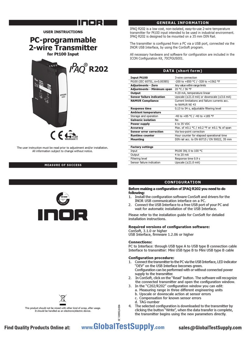
INOR IPAQ R202 User manual

INOR

INOR IPAQ R202 User manual

INOR IPAQ-H/HX User manual

INOR

INOR IPAQ-H/HX User manual

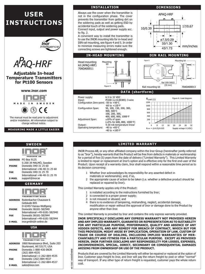
INOR APAQ-HRF User manual

INOR

INOR APAQ-HRF User manual

INOR IPAQ C520 User manual

INOR

INOR IPAQ C520 User manual

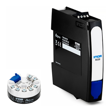
INOR IPAQ C330 Series User manual

INOR

INOR IPAQ C330 Series User manual

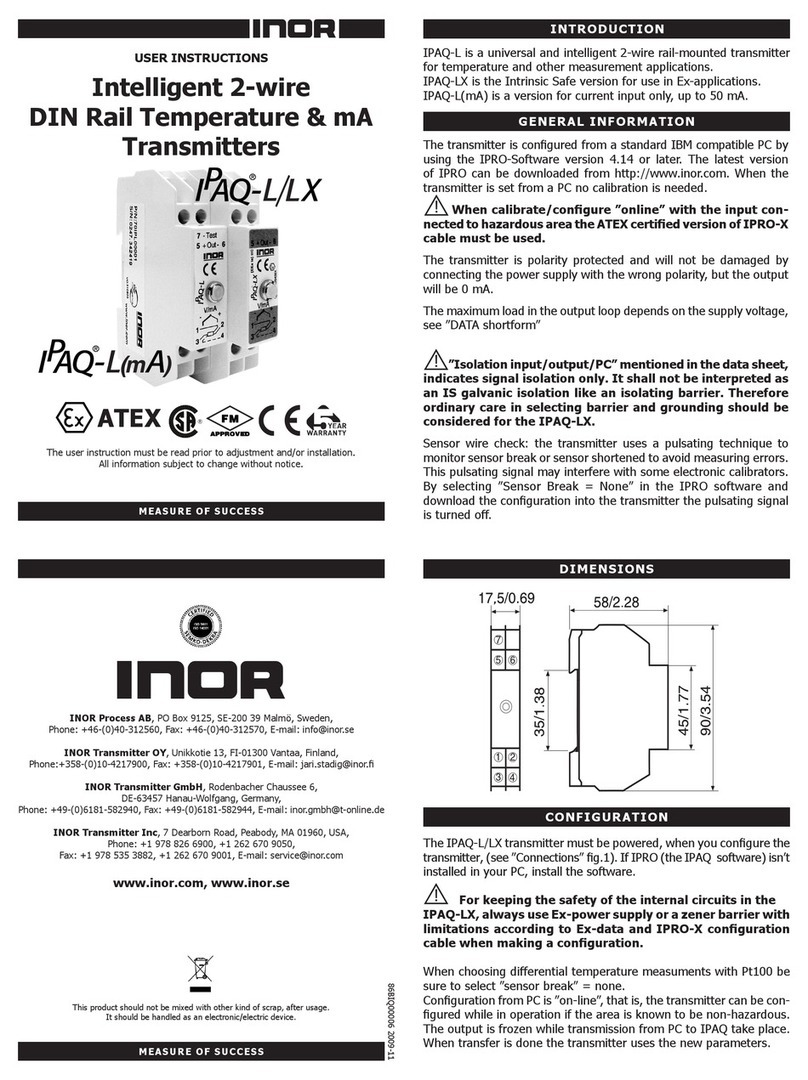
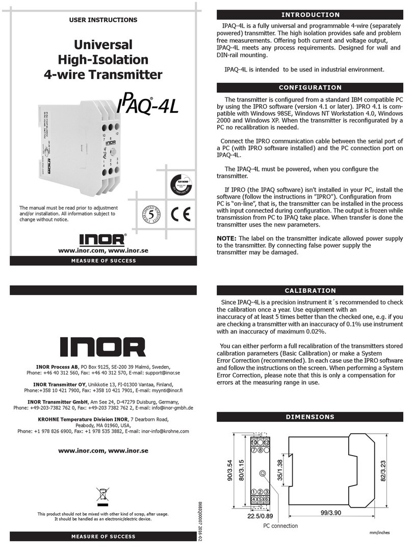
INOR IPAQ-4L User manual

INOR

INOR IPAQ-4L User manual

INOR APAQ C130 User manual

INOR

INOR APAQ C130 User manual

INOR Mini IPAQ-HLP User manual

INOR

INOR Mini IPAQ-HLP User manual

INOR IPAQ C520 Wiring diagram

INOR

INOR IPAQ C520 Wiring diagram

INOR IPAQ-L User manual

INOR

INOR IPAQ-L User manual

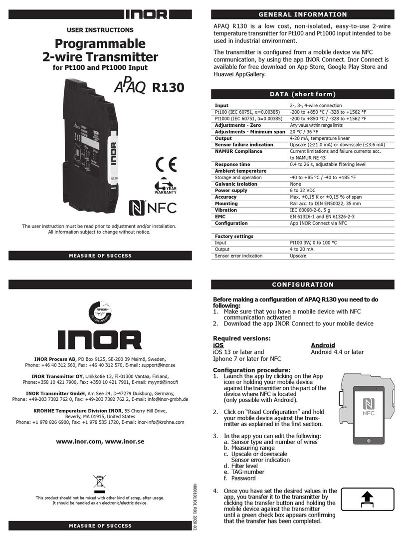
INOR APAQ R130 User manual

INOR

INOR APAQ R130 User manual

INOR ICON-X Wiring diagram

INOR

INOR ICON-X Wiring diagram

INOR IPAQ-LX User manual

INOR

INOR IPAQ-LX User manual

Popular Transmitter manuals by other brands

IROX JKR-1 user manual

IROX

IROX JKR-1 user manual

MEXPO WT-300 G2 user manual

MEXPO

MEXPO WT-300 G2 user manual

Williams Sound Personal PA PPA T36 Instructions for use and care

Williams Sound

Williams Sound Personal PA PPA T36 Instructions for use and care

Honeywell 5819AP Installation and setup guide

Honeywell

Honeywell 5819AP Installation and setup guide

SenseAir aSENSE RL user manual

SenseAir

SenseAir aSENSE RL user manual

evertz 7707MTA-HD manual

evertz

evertz 7707MTA-HD manual

Wave Central AXIS TX PICO PLUS Menu information

Wave Central

Wave Central AXIS TX PICO PLUS Menu information

Extron electronics XTP T HWP 101 user guide

Extron electronics

Extron electronics XTP T HWP 101 user guide

Voyager AC110/120V Operation and installation instructions

Voyager

Voyager AC110/120V Operation and installation instructions

Dolphin PTM 330 user manual

Dolphin

Dolphin PTM 330 user manual

SILENTSYSTEM TX-300-MOBI owner's guide

SILENTSYSTEM

SILENTSYSTEM TX-300-MOBI owner's guide

AIRTRONICS SD-6G operating manual

AIRTRONICS

AIRTRONICS SD-6G operating manual

Smartwares SH5-TBR-A quick guide

Smartwares

Smartwares SH5-TBR-A quick guide

Ramsey Electronics FM10A user manual

Ramsey Electronics

Ramsey Electronics FM10A user manual

Bluestream HEX31WP-TX user manual

Bluestream

Bluestream HEX31WP-TX user manual

Hamilton HAMILTON AM1000 installation manual

Hamilton

Hamilton HAMILTON AM1000 installation manual

Edge FM Transmitter quick start guide

Edge

Edge FM Transmitter quick start guide

Radwin TERRABRIDGE installation guide

Radwin

Radwin TERRABRIDGE installation guide

manuals.online logo
manuals.online logoBrands
  • About & Mission
  • Contact us
  • Privacy Policy
  • Terms and Conditions

Copyright 2025 Manuals.Online. All Rights Reserved.