PCT PCT-FTX3R User manual

1715 West Sunrise Boulevard
Gilbert, Arizona 85233
Toll Free: 800.315.2253
Phone: 480.813.0925
Fax: 480.892.5537
www.pctusa.net
Model
Product Operations
Manual
PCT-FTX3R
VER 2 - 06282005
CATV 1310nm DFB
Fiber Optic Transmitter
All manuals and user guides at all-guides.com
all-guides.com

1715 West Sunrise Boulevard
Gilbert, Arizona 85233
Toll Free: 800.315.2253
Phone: 480.813.0925
Fax: 480.892.5537
www.pctusa.net
Product Operations Manual
Model
PCT-FTX3R
CATV 1310nm DFB
Fiber Optic Transmitter
STATEMENT OF WARRANTY
PCT-International, Inc. warrants this product to be free of defects in workmanship, materials, and
manufacture for a period of one (1) year from date of purchase. Further, PCT-International, Inc. will repair
and/or replace this product or its components that have been proven defective during the warranted period
of one (1) year. This warranty shall not apply to product(s) which has had the factory seal broken, or has
been subjected to misuse, neglect, accidental damage, incorrect wiring, improper installation, or use in
violation of authorized instructions. Removal of the product's nameplate, bearing model number and serial
number, shall also void this warranty coverage. Warranty shall not be enlarged, diminished, or affected by,
nor shall further obligation or liability arise from PCT-International, Inc.'s rendering of technical advice or
service in connection with the purchaser's order for this product.
This manual contains information, illustrations, and technical data that pertain to the operation of model PCT-FTX3R,
CATV 1310nm DFB fiber optic transmitter. Pursuant to sections of Title 21, United States Code of Federal Regulation
(CFR), Chapter I, Subchapter J, and administered by the Center for Devices and Radiological Health (CD RH),
operating under the Food and Drug Administration (FDA), this product which produces or receives an optical signal
composed of laser radiation, complies with 21 CFR Chapter I, Subchapter J, as applicable to Class I laser products.
DANGER - AVOID DIRECT EXPOSURE TO THE LASER BEAM AT ALL TIMES. Invisible
radiation continues when open or when operating with fiber optic cable disconnected. Never operate
unit with a broken fiber or with a disconnected and/or unterminated fiber connector.
!
CAUTION -There are no user-serviceable parts inside the unit. Refer all servicing to qualified service
personnel. Make no attempt to modify or alter any circuit or component assembly, other than those
measurements, adjustments, and tests specified in this manual. Unauthorized modifications to this unit
will result in nullification of warranty coverage.
!
Page 2
VER 2 - 06282005
All manuals and user guides at all-guides.com
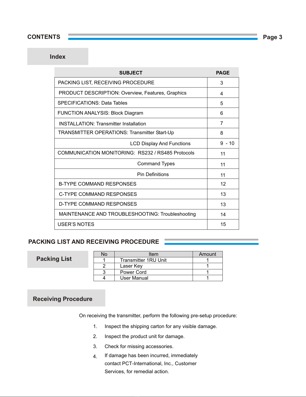
CONTENTS
No Item Amount
1 Transmitter 1RU Unit 1
2 Laser Key 1
3 Power Cord 1
4 User Manual 1
PACKING LIST AND RECEIVING PROCEDURE
Packing List
On receiving the transmitter, perform the following pre-setup procedure:
1. Inspect the shipping carton for any visible damage.
2. Inspect the product unit for damage.
3. Check for missing accessories.
4. If damage has been incurred, immediately
contact PCT-International, Inc., Customer
Services, for remedial action.
Receiving Procedure
Page 3
Index
SUBJECT PAGE
PACKING LIST, RECEIVING PROCEDURE
PRODUCT DESCRIPTION: Overview, Features, Graphics
SPECIFICATIONS: Data Tables
FUNCTION ANALYSIS: Block Diagram
INSTALLATION: Transmitter Installation
TRANSMITTER OPERATIONS: Transmitter Start-Up
LCD Display And Functions
COMMUNICATION MONITORING: RS232 / RS485 Protocols
Command Types
Pin Definitions
B-TYPE COMMAND RESPONSES
C-TYPE COMMAND RESPONSES
USER’S NOTES
D-TYPE COMMAND RESPONSES
MAINTENANCE AND TROUBLESHOOTING: Troubleshooting
3
4
5
6
7
8
9 - 10
11
11
11
12
13
13
14
15
All manuals and user guides at all-guides.com
Features
Transmitter Graphic
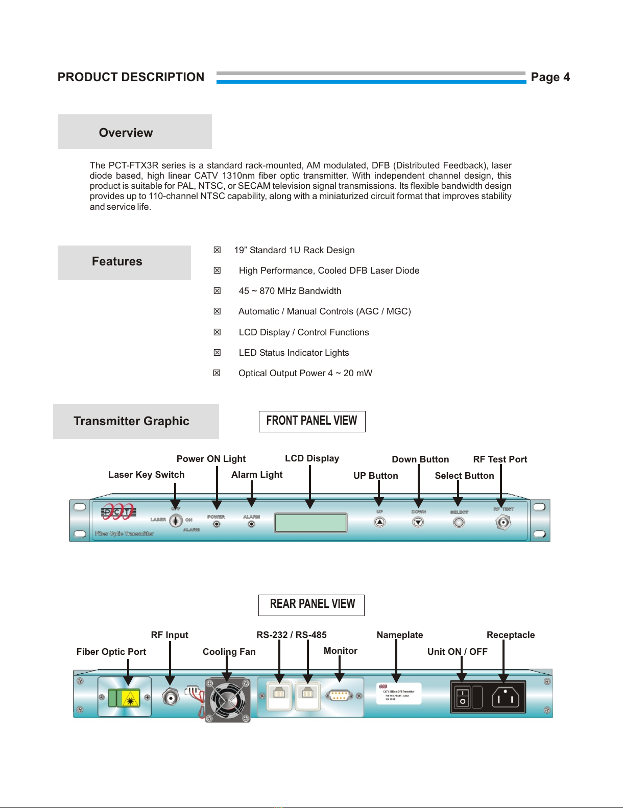
PRODUCT DESCRIPTION
The PCT-FTX3R series is a standard rack-mounted, AM modulated, DFB (Distributed Feedback), laser
diode based, high linear CATV 1310nm fiber optic transmitter. With independent channel design, this
product is suitable for PAL, NTSC, or SECAM television signal transmissions. Its flexible bandwidth design
provides up to 110-channel NTSC capability, along with a miniaturized circuit format that improves stability
and service life.
T19” Standard 1U Rack Design
THigh Performance, Cooled DFB Laser Diode
T45 ~ 870 MHz Bandwidth
TAutomatic / Manual Controls (AGC / MGC)
TLCD Display / Control Functions
TLED Status Indicator Lights
Optical Output Power 4 ~ 20 mW
REAR PANEL VIEW
Fiber Optic Port
RF Input RS-232 / RS-485 Receptacle
Unit ON / OFF
Nameplate
Cooling Fan Monitor
FRONT PANEL VIEW
Laser Key Switch
Power ON Light
Alarm Light
LCD Display
UP Button
Down Button
Select Button
RF Test Port
Overview
Page 4
T
All manuals and user guides at all-guides.com
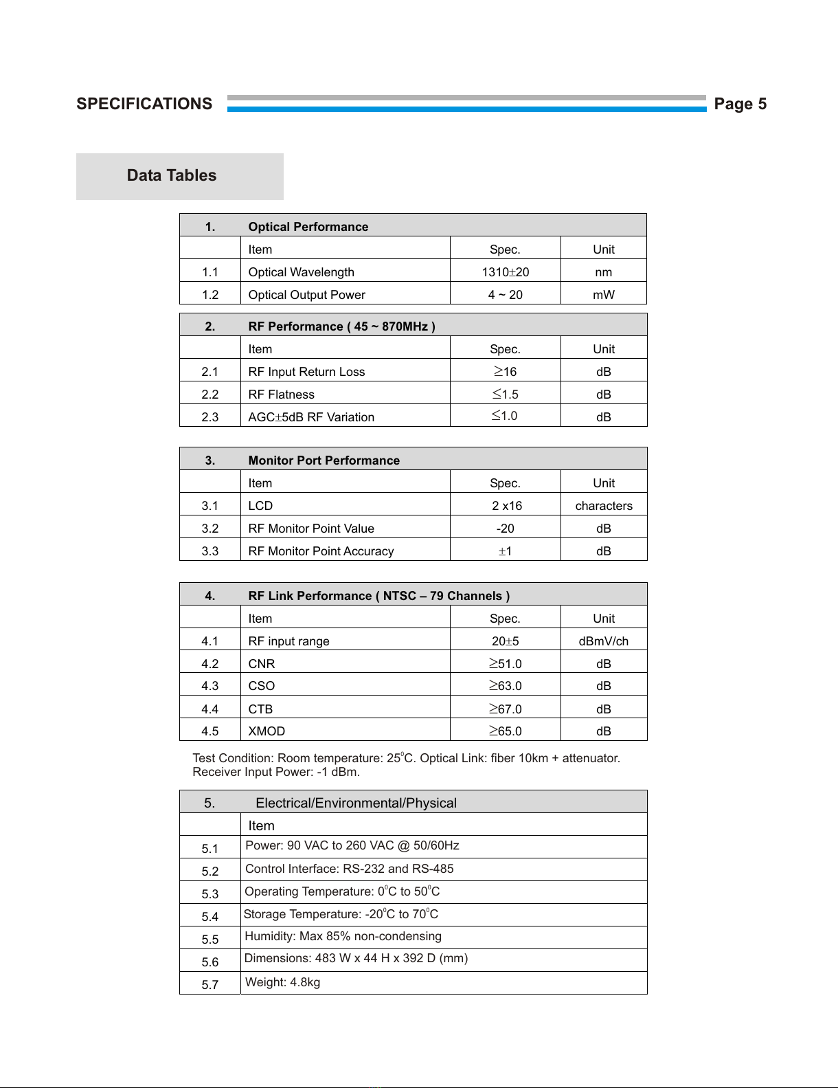
1. Optical Performance
Item Spec. Unit
1.1 Optical Wavelength 1310±20 nm
1.2 Optical Output Power 4 ~ 20 mW
2. RF Performance ( 45 ~ 870MHz )
Item Spec. Unit
2.1 RF Input Return Loss ³16 dB
2.2 RF Flatness £1.5 dB
2.3 AGC±5dB RF Variation dB
3. Monitor Port Performance
Item Spec. Unit
3.1 LCD 2 x16 characters
3.2 RF Monitor Point Value -20 dB
3.3 RF Monitor Point Accuracy ±1 dB
4. RF Link Performance ( NTSC – 79 Channels )
Item Spec. Unit
4.1 RF input range 20±5 dBmV/ch
4.2 CNR ³51.0 dB
4.3 CSO ³63.0 dB
4.4 CTB ³67.0 dB
4.5 XMOD ³65.0 dB
0
Test Condition: Room temperature: 25 C. Optical Link: fiber 10km + attenuator.
Receiver Input Power: -1 dBm.
5. Electrical/Environmental/Physical
Item
5.1
5.2
5.3
5.4
5.5
5.6
5.7
Power: 90 VAC to 260 VAC @ 50/60Hz
Control Interface: RS-232 and RS-485
00
Operating Temperature: 0 C to 50 C
Weight: 4.8kg
Dimensions: 483 W x 44 H x 392 D (mm)
Humidity: Max 85% non-condensing
00
Storage Temperature: -20 C to 70 C
SPECIFICATIONS
Data Tables
Page 5
£1.0
All manuals and user guides at all-guides.com
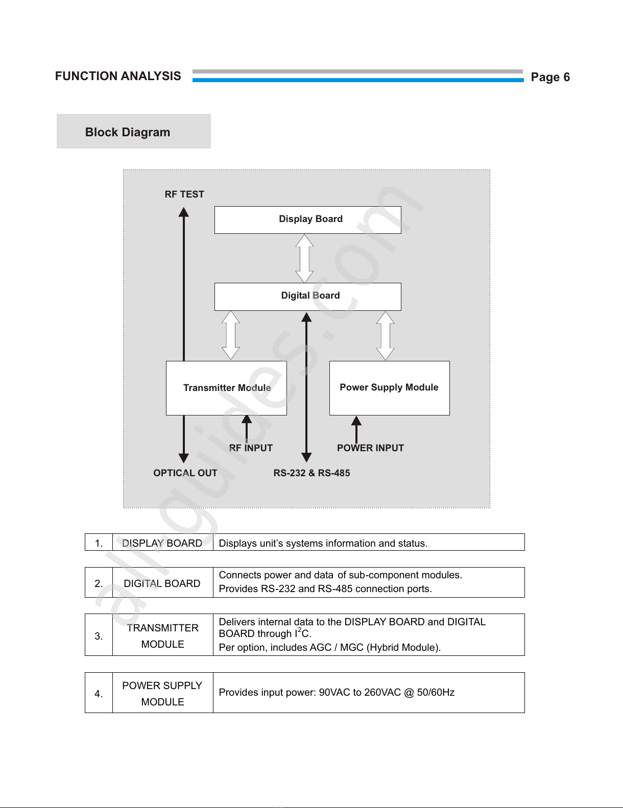
FUNCTION ANALYSIS
RF TEST
OPTICAL OUT
RF INPUT POWER INPUT
RS-232 & RS-485
Display Board
Digital Board
Transmitter Module Power Supply Module
Block Diagram
Page 6
1. DISPLAY BOARD Displays unit’s systems information and status.
2. DIGITAL BOARD Connects power and data of sub-component modules.
Provides RS-232 and RS-485 connection ports.
3. TRANSMITTER
MODULE
Delivers internal data to the DISPLAY BOARD and DIGITAL
BOARD through I2C.
Per option, includes AGC / MGC (Hybrid Module).
4. POWER SUPPLY
MODULE
Provides input power: 90VAC to 260VAC @ 50/60Hz
All manuals and user guides at all-guides.com
all-guides.com

CLEANING FIBER OPTIC CONNECTORS
1. Use a lint-free cloth (3cm x 3cm recommended) .
2. Moisten one-half of the cloth with >90% ethyl alcohol.
3. Gently swab the connector’s endface.
4. Using the dry half of the cloth, wipe the endface.
5. Allow the connector to air -dry completely before inserting
into the adapter port.
CAUTION: Do NOT spray compressed air directly into the
connector’s endface. Air blasting may cause abrasion damage.
!
DANGER - AVOID DIRECT OCULAR EXPOSURE TO THE LASER BEAM AT ALL
TIMES. Invisible radiation continues when operating with an open or disconnected
fiber optic cable. Such exposure may result in severe physical damage. Do NOT
operate this unit with a broken, disconnected, or unterminated fiber connector.
INSTALLATION
Transmitter Installation
Page 7
Step 1 Align the transmitter’s base plate with the rack -mount cabinet guides. Slide unit
into position. Tighten the four (4) front panel mounting screws.
Step 2 Check to ensure for adequate ventilation of heat from all sides of the unit.
Maximum temperature at bottom of transmitter should not exceed 50 0C.
In general, allow for a 1.75” vertical space above the installed unit to assist
heat dissipation.
Note: Transmitter will generate approximately 15 0C heat over ambient.
Step 3 Install Power Supply.
Step 4 Ensure the Laser Key Switch on the front panel is in the OFF position.
Step 5 Check to confirm the Optical Connector is the correct, matched type.
Recommendation: Clean the optical connector endface before connecting to
the transmitter optical port.
Step 6 Connect the Fiber Optic interface.
OPTICAL Connection Procedure
1. Check fiber optic cable for bends and creases that can distort transmitter
performance.
2. Confirm the compatibility of fiber optic connectors. (FC/APC and SC/APC)
All manuals and user guides at all-guides.com

TRANSMITTER OPERATIONS
Transmitter Start-Up
1. Ensure the Laser Power Switch on the front panel is set in the OFF position.
2.
Turn on the unit power using the ON/OFF switch on the rear panel.
The green lighted POWER LED on the front panel will illuminate.
3. Turn the Laser Power Switch to the ON position. The LCD display will, now,
indicate “Laser ON”.
4. Note: If the unit is functioning properly, the ALARM Display light will remain
unlit. A red light illumination of the ALARM Display indicates the transmitter
is malfunctioning.
RF Connection
Confirm the RF input power is set to the correct level. Note: Incorrect RF
input will cause noise and distortion performance of the transmitter.
RF Input
1. Connect RF power input interface at the RF port on the rear panel.
2. Connect RF monitoring device to the RF TEST PORT on the front panel.
Note: RF TEST PORT signals will be 20 dB below R F Input signals.
Page 8
All manuals and user guides at all-guides.com

PCT-FTX3R
Laser ON/OFF
or
Alarm Display
PCT TRANSMITTER
10 Seconds Interval
Optical Menu
Output = **.*mW
Bias = *****mA
Temp = **.*C
EXIT
System Menu
P/N = *******
S/N = *******
Ver = *******
Ch = *******
ID = *******
EXIT
EXIT
RF Menu
AGC/MCG Level = +/- **
AGC/MCG Set = +/- **
EXIT
LCD Display And Functions
LCD DISPLAY FUNCTION
Optical Menu Optical Status
Output= **.*mV Monitors Optical Power Status
Bias=*****mA Monitors Laser Current Status
Temp=**.*C Monitors Laser Temperature Status
RF Menu RF Status
AGC Level= +/- ** AGC MGC and Level Display
AGC Set= +/- ** AGC MGC Select and Level Adjustment Function
System Menu System Status
P/N= ******* Product Number Displayed
S/N= ******* Product Serial Number Displayed
Ver=******* Software Version Number Displayed
CH=******* Channel Type and Number Displayed
ID=******** Communication Number Displayed
Page 9
All manuals and user guides at all-guides.com
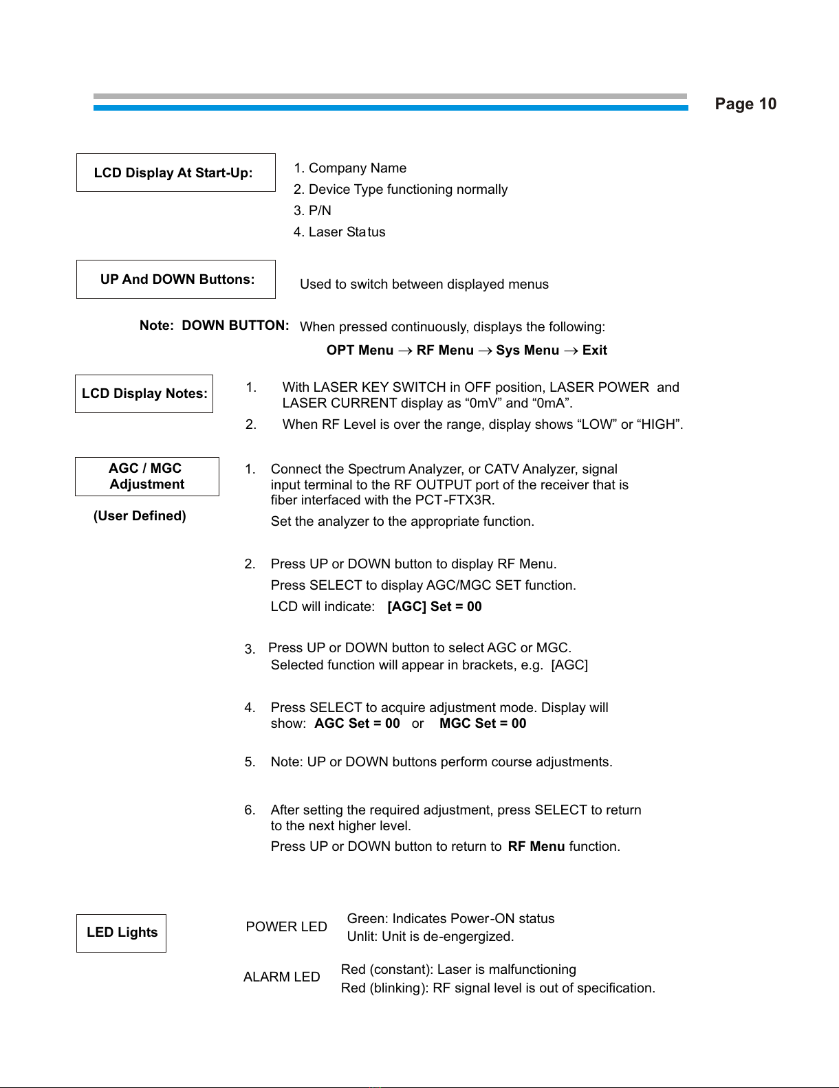
LCD Display At Start-Up: 1. Company Name
2. Device Type functioning normally
3. P/N
4. Laser Status
Used to switch between displayed menus
UP And DOWN Buttons:
Note: DOWN BUTTON:
When pressed continuously, displays the following:
OPT Menu ®RF Menu ®Sys Menu ®Exit
LCD Display Notes:
1. With LASER KEY SWITCH in OFF position, LASER POWER and
LASER CURRENT display as “0mV” and “0mA”.
2. When RF Level is over the range, display shows “LOW” or “HIGH”.
AGC / MGC
Adjustment
1. Connect the Spectrum Analyzer, or CATV Analyzer, signal
input terminal to the RF OUTPUT port of the receiver that is
fiber interfaced with the PCT-FTX3R.
Set the analyzer to the appropriate function.
2. Press UP or DOWN button to display RF Menu.
Press SELECT to display AGC/MGC SET function.
LCD will indicate: [AGC] Set = 00
3. Press UP or DOWN button to select AGC or MGC.
Selected function will appear in brackets, e.g. [AGC]
4. Press SELECT to acquire adjustment mode. Display will
show: AGC Set = 00 or MGC Set = 00
5. Note: UP or DOWN buttons perform course adjustments.
6. After setting the required adjustment, press SELECT to return
to the next higher level.
Press UP or DOWN button to return to RF Menu function.
LED Lights POWER LED Green: Indicates Power-ON status
Unlit: Unit is de-engergized.
ALARM LED Red (constant): Laser is malfunctioning
Red (blinking): RF signal level is out of specification.
Page 10
(User Defined)
All manuals and user guides at all-guides.com

COMMUNICATION MONITORING
Command Types
RS232 / RS485 Protocols
RS232 RS485 Pin Definitions
Page 11
COM
TYPE DESCRIPTION FORMAT RESPONSE
B Returns Tx status in binary
format
Hex 1a See Table 1: B type command response
C Returns alarm message in binary
format
Hex 1c See Table 2: C type command response
D Set Parameter Hex 1b See Table 3: D type command response
RS232 RS485
Pin 1 NC Pin 1 NC
Pin 2 TX Pin 2 TR+
Pin 3 RX Pin 3 RX+
Pin 4 NC Pin 4 TR-
Pin 5 GND Pin 5 RX-
Pin 6 NC Pin 6 NC
Pin 7 NC
Pin 8 NC
Pin 9 NC
A. Use all capital letters to input commands and responses.
B. Letters “xxxx” represent the unit’s ID -CODE.
C. When using RS-232, key in ID-CODE directly.
All manuals and user guides at all-guides.com
all-guides.com
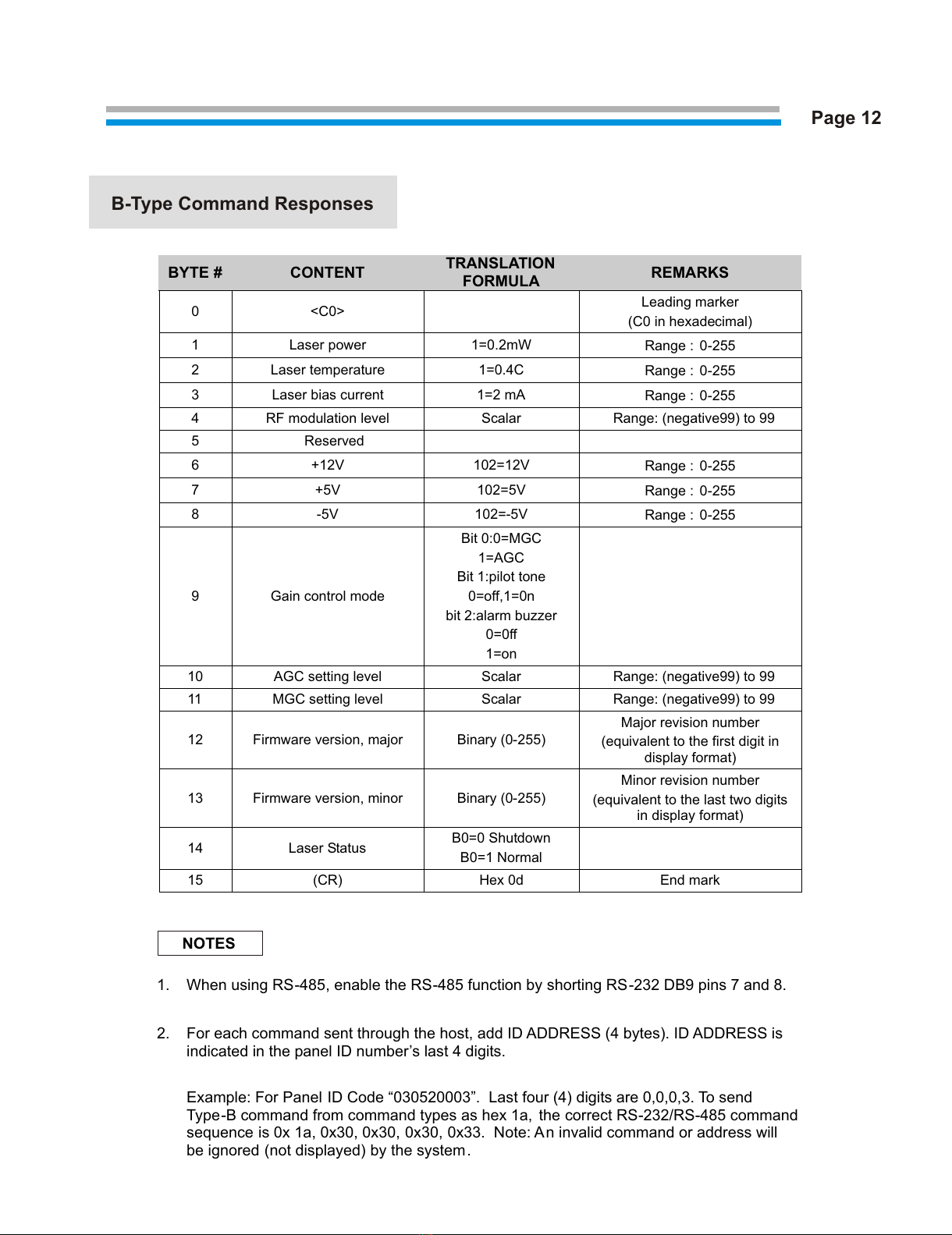
B-Type Command Responses
Page 12
NOTES
BYTE # CONTENT TRANSLATION
FORMULA REMARKS
0 <C0> Leading marker
(C0 in hexadecimal)
1 Laser power 1=0.2mW Range : 0-255
2 Laser temperature 1=0.4C Range : 0-255
3 Laser bias current 1=2 mA Range : 0-255
4 RF modulation level Scalar Range: (negative99) to 99
5 Reserved
6 +12V 102=12V Range : 0-255
7 +5V 102=5V Range : 0-255
8 -5V 102=-5V Range : 0-255
9 Gain control mode
Bit 0:0=MGC
1=AGC
Bit 1:pilot tone
0=off,1=0n
bit 2:alarm buzzer
0=0ff
1=on
10 AGC setting level Scalar Range: (negative99) to 99
11 MGC setting level Scalar Range: (negative99) to 99
12 Firmware version, major Binary (0-255)
Major revision number
(equivalent to the first digit in
display format)
13 Firmware version, minor Binary (0-255)
Minor revision number
(equivalent to the last two digits
in display format)
14 Laser Status B0=0 Shutdown
B0=1 Normal
15 (CR) Hex 0d End mark
1. When using RS-485, enable the RS-485 function by shorting RS-232 DB9 pins 7 and 8.
2. For each command sent through the host, add ID ADDRESS (4 bytes). ID ADDRESS is
indicated in the panel ID number’s last 4 digits.
Example: For Panel ID Code “030520003”. Last four (4) digits are 0,0,0,3. To send
Type-B command from command types as hex 1a, the correct RS-232/RS-485 command
sequence is 0x 1a, 0x30, 0x30, 0x30, 0x33. Note: An invalid command or address will
be ignored (not displayed) by the system.
All manuals and user guides at all-guides.com

C-Type Command Responses
D-Type Command Responses (6bytes)
Page 13
1. B0=bit 0 (LSB), B1=bit 1, B2=bit 2
2. Bit set=alarm, bit clear=no alarm
3. All byte is add hex 0x30
NOTES
BYTE # DESCRIPTION BIT DEFINITION REMARKS
0 <C0> Leading marker, in
hexadecimal
1 Laser power,
alarm status
B0 : laser power alarm
2
Laser
temperature,
alarm status
B0 : temp. low alarm
B1 : temp. high alarm
B2 : temp. too high alarm
Laser will be shutdown
when too high
3 Bias alarm
status
B0 : Laser bias alarm
4 RF Mod. Lvl.
Alarm status
B0 : RF level low alarm
B1 : RF level high alarm
5 <CR> Hex 0d End mark
BYTE # DESCRIPTION DEFINITION REMARKS
0 Set gain control mode 000=MGC mode
001=AGC mode
1 Set Laser On/Off 000=Laser off
001=Laser on
2 Set AGC Value Valid range=-99 to +99
3 Set MGC Value Valid range=-99 to +99
All manuals and user guides at all-guides.com
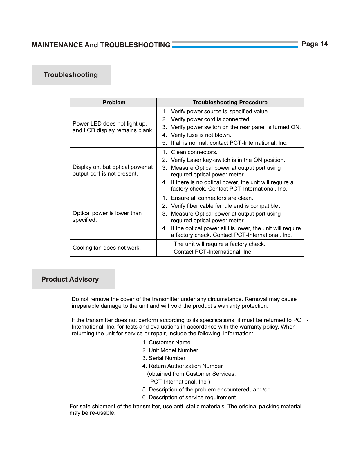
MAINTENANCE And TROUBLESHOOTING
Problem Troubleshooting Procedure
Power LED does not light up,
and LCD display remains blank.
.
1. Verify power source is specified value.
2. Verify power cord is connected.
3. Verify power switc h on the rear panel is turned ON.
4. Verify fuse is not blown.
5. If all is normal, contact PCT-International, Inc.
Display on, but optical power at
output port is not present.
1. Clean connectors.
2. Verify Laser key -switch is in the ON position.
3. Measure Optical power at output port using
required optical power meter.
4. If there is no optical power, the unit will require a
factory check. Contact PCT-International, Inc.
Optical power is lower than
specified.
1. Ensure all connectors are clean.
2. Verify fiber cable fer rule end is compatible.
3. Measure Optical power at output port using
required optical power meter.
4. If the optical power still is lower, the unit will require
a factory check. Contact PCT-International, Inc.
Cooling fan does not work. The unit will require a factory check.
Contact PCT-International, Inc.
Troubleshooting
Product Advisory
Do not remove the cover of the transmitter under any circumstance. Removal may cause
irreparable damage to the unit and will void the product’s warranty protection.
If the transmitter does not perform according to its specifications, it must be returned to PCT -
International, Inc. for tests and evaluations in accordance with the warranty policy. When
returning the unit for service or repair, include the following information:
1. Customer Name
2. Unit Model Number
3. Serial Number
4. Return Authorization Number
(obtained from Customer Services,
PCT-International, Inc.)
5. Description of the problem encountered , and/or,
6. Description of service requirement
For safe shipment of the transmitter, use anti -static materials. The original packing material
may be re-usable.
Page 14
All manuals and user guides at all-guides.com

Page 15
USER’S NOTES
For Technical Assistance or Sales Information,
contact:
1715 W. Sunrise Blvd., Gilbert, AZ 85233
Phone: 800.315.2253 480.813.0925
Fax: 480.892.5537
All manuals and user guides at all-guides.com
Other manuals for PCT-FTX3R
1
Table of contents
Other PCT Transmitter manuals

Popular Transmitter manuals by other brands

Phonak
Phonak inspiro V3 Service manual

Terra
Terra mo411BL manual

Phottix
Phottix PH89092 user manual

Dwyer Instruments
Dwyer Instruments Magnesense II MS2-X102 Installation and operating instructions

TX
TX HDBaseT user manual

Prosense
Prosense AUTOMATIONDIRECT DPTW Series Installation and maintenance instructions


