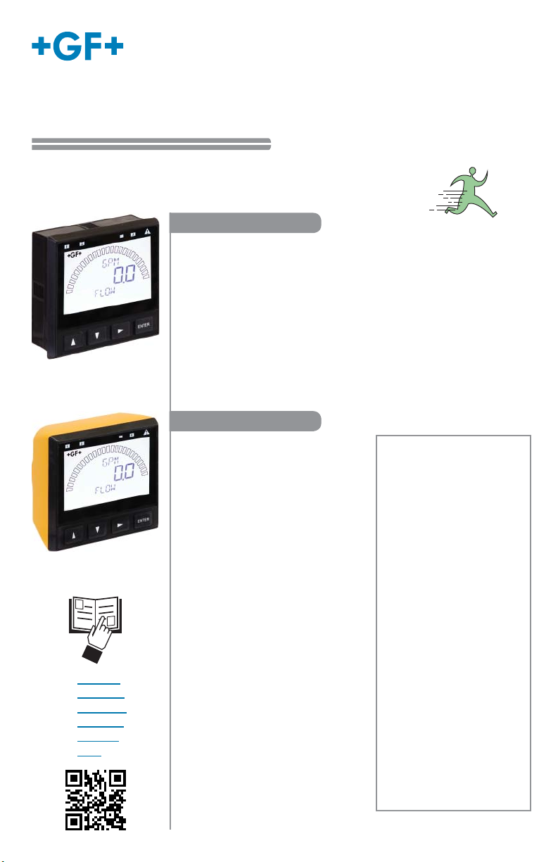
Signet 9900 Transmitter
3-9900.091 Rev. 7 07/18 English
*3-9900.091*
Start-Up Guide
Look for the Quick Start icon to
quickly set up your new 9900.
The 9900 is compatible with all
GF Signet products listed in the
column to the right.
• pH and ORP electrodes require the
Signet 2750/2751 DryLoc®Sensor
Electronics (sold separately).
• Conductivity/Resistivity or Salinity
measurement requires either
the optional Direct Conductivity/
Resistivity Module (part number
3-9900.394) or the Signet 2850
Conductivity/Resistivity Sensor
Electronics (sold separately).
NOTE: If using the 2850, use ONLY
the one-channel Digital (S3L) models
3-2850-51/-61, or the 2-channel
model 3-2850-63 with only one
channel connected. Do not use
with both channels connected. The
4 to 20 mA models 3-2850-52 and
3-2850-62 are not compatible with
the 9900.
• Turbidity measurement using
Signet 4150 or Dissolved
• Oxygen measurement using
Signet 2610-31 requires Signet
8058 i-Go®Signal Converter
(sold separately).
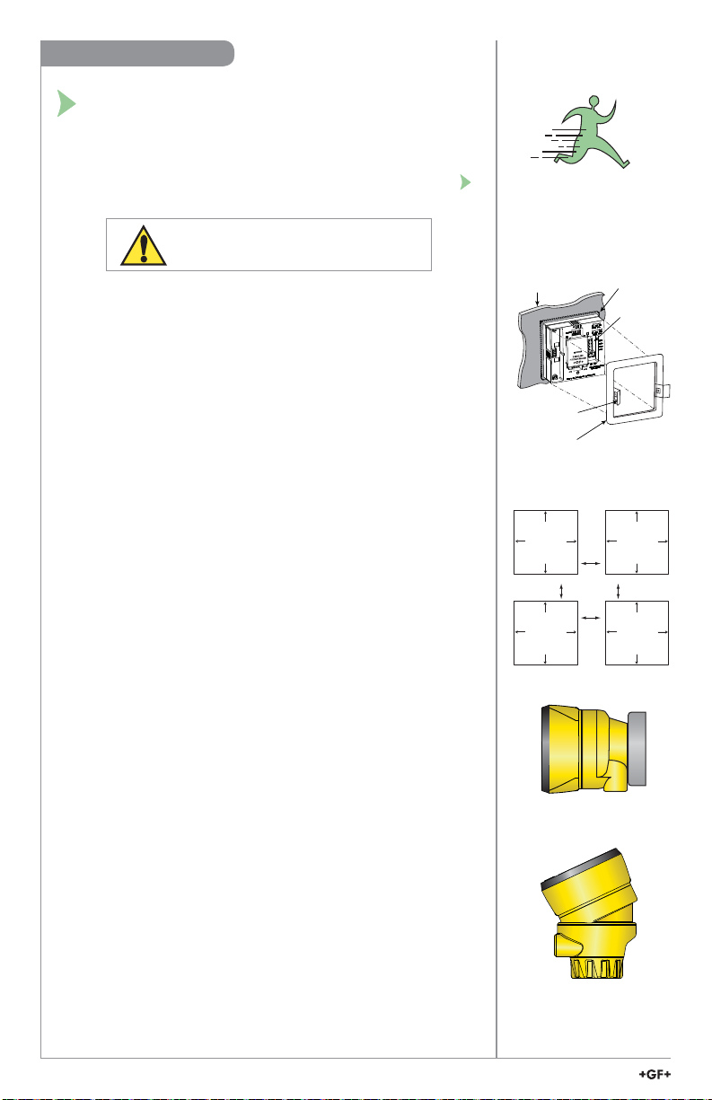
Field Mount
Panel Mount
English, Deutsch, 中文
The 9900 Transmitter, a member of Signet's line of SmartPro®
instruments, provides a single-channel interface for all Flow,
pH/ORP, Conductivity/Resistivity, Salinity, Pressure, Temperature,
Level, Dissolved Oxygen, Turbidity, Batch and other applications.
The 9900 is available in either Panel or Field Mount, runs on
10.8 to 35.2 VDC power (24 VDC nominal), and can power
certain sensors on loop power (see NOTE on page 7).
The 9900 Transmitter, also allows third-party 4 to 20 mA signals
to be used as an input (optional Signet 8058 i-Go®Signal
Converter required, sold separately).
• English
• Deutsch
• Français
• Español
• Italiano
• 中文
Compatibility
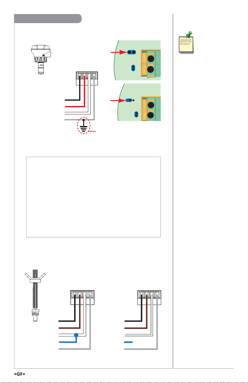
Flow
515*/8510*, 525*, 2000,
2100, 2507, 2536*/8512*,
2537, 2540*, 2551, 2552
pH/ORP
2724-2726 with 2750*/2751
2734-2736 with 2750*/2751
2756-WTx–2757-WTx with
3719 and 2750*/2751
2764-2767 with 2750*/2751
2774-2777 with 2750*/2751
Conductivity/Resistivity,
Salinity
2819-2823 with 2850 or
Cond/Res Module
2839-2842 with 2850 or
Cond/Res Module
Level, Temperature,
Pressure
2250*, 2350*, 2450*
Turbidity
4150 requires 8058
Dissolved Oxygen
2610-41, 2610-51 direct
to 9900
*Can be run on Loop Power
(see NOTE on page 7)
Description