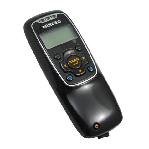
E-Seek 200 Operating instructions

- 1 -
Model 200 / 250 / 260
Programming Guide
E-SEEK Inc.
R & D Center
9471 Ridgehaven Court #E
San Diego, CA 92123
Tel: 858-495-1900
Fax: 858-495-1901
Sales & Marketing
245 Fischer Ave #D5
Costa Mesa, CA 92626
Tel: 714-545-3316
Fax: 714-545-3595
www.e-seek.com
Last Revised by April 1, 2011
Rev: S04F

- 2 -

- 3 -
This Programming Specification may be revised or withdrawn at any time.
All rights reserved. No part of this publication may be reproduced in any form, in an electronic
retrieval system or otherwise, without the prior written permission of the publisher.

- 4 -
Serial Programming Specifications
Serial Command Structure
“Start Character”<Command 1>…<Command n>“End Character”
The command structure consists of:
-Start character
-Command/s
-End character
Start Character
Every serial programming starts with an SOH character (ASCII value 01). The SOH
character is needed only once for each set of commands, for example if you need to
send two consecutive commands, it would require one SOH character followed by the
two commands and the End character.
Commands
Each command data is bounded in <> characters. For example, the factory default
command is
<FACDEF=1>
End Character
At the end of each set of command\s, the end character EOT (ASCII value 04) is
required.
Scanner Responds
After each successful command\s, the scanner will respond with an ACK character. If the
command is incomplete or out of rang, then the scanner responds with a NAK character.
Example:
This is a command for setting the Factory defaults :
“SOH”<FACDEF=1>”EOT”
In Visual Basic:
Dim Command As String
Command = Chr$(1) & "<FACDEF=1>" & Chr$(4)
And the scanner response is:
ACK
Changes will be effective after scanner ACK response.

- 5 -
Factory Setup
Description: To restore all factory settings, this command will overwrite all existing
setting with the factory default settings.
Scanner Response: ACK if the factory restore is completed successfully / NAK
Description
Field
Values allowed
Factory Default
Default
FACDEF=1
Table 1.1
Scanner Settings
Description: To request current setting parameters (SETPAR), scanner model number
(FINGER) or request a respond to a ping command (TXPING).
Scanner Response: (SETPAR) ACK followed by a complete list of settings, (each
field is sent separately with its start and stop character) and
followed by \r\n after the last field/ NAK
(FINGER) ACK followed by a model name and \r\n / NAK
(TXPING) ACK / NAK
Description
Field
Values allowed
Current Settings
SETPAR:
Send Scanner Model
FINGER:
Sending a Ping
TXPING:
Table 1.2
Scanner Revisions
Description: To request an Application 1, 2 or Hardware revision number.
Scanner Response: (APP1RV) ACK “N.NN.NN\r\n” / NAK
(APP1RV) ACK “N.NN.NN\r\n” / NAK
(HARDRV) ACK “N.NN.NN\r\n” / NAK
(SERIAL) ACK “NNNNNNNNNN\r\n” / NAK
N is an ASCII „0‟ – „9‟, All responses have a fixed length
Description
Field
Values allowed
Send Revision Number
Application 1
APP1RV:
Application 2
APP2RV:
Hardware
HARDRV:
Table 1.3

- 6 -
Serial Number Read & Setup
Description: The maximum length is 30 characters and no control character is allowed
for a serial number.
Example: „SOH‟<SERIAL:>„EOT‟
Scanner Response: ACK “XXXXXXXXXX…\r\n” / NAK
X is a printable ASCII, with variable length
Description: When this option is enabled the data will be sent before the decoded data.
The default is a „disable‟.
Scanner Response: ACK / NAK
Description
Field
Values allowed
Serial Number Read
SERIAL:
Add to stream
Enable
SERIEN=1
Disable *
SERIEN=0
Table 1.4
Web Setup
Description: To request a web address stored in the scanner.
Scanner Response: ACK “www. …\r\n” / NAK
Response is a variable length
Description
Field
Values allowed
Web Site Information
WWW
WEBSIT:
Table 1.5
*Marks indicate the factory default setting

- 7 -
Serial Port Setup
Description: To setup serial port parameters, changes will be effective after scanner
ACK response.
Host Requirement: The Character Delay range is between 0 ms –50 ms
Scanner Response: ACK / NAK
Description
Field
Values allowed
RS232 Data Bits
8 *
RSBITS=8
7
RSBITS=7
RS232 Parity
None *
RSPRTY=NONE
Odd
RSPRTY=ODD
Even
RSPRTY=EVEN
RS232 Stop Bits
1 *
RSSTOP=1
2
RSSTOP=2
RS232 Hardware Flow
Control
Enable
RSCTSE=1
Disable *
RSCTSE=0
RS232 Baud Rate
1200
RSBAUD=1200
2400
RSBAUD=2400
4800
RSBAUD=4800
9600 *
RSBAUD=9600
19200
RSBAUD=19200
38400
RSBAUD=38400
57600
RSBAUD=57600
115200
RSBAUD=115200
RS232 Character Delay
0 ms *
RSDELY=000
Table 2.1

- 8 -
Registration Key Read & Write
Description: To setup Registration Key, changes will be effective after scanner ACK
response. Control characters are not permitted. The maximum length is 30 characters*.
When the REGIEN option is enabled, the data will be added between serial number and
decoded data.
Example: „SOH‟<REGKEY:>„EOT‟
Scanner Response: ACK “XXXXXXXXXX…\r\n” / NAK
X is a printable ASCII, with variable length
Scanner Response: ACK / NAK
Description
Field
Values allowed
Reg. Key Read
REGKEY:
Add to stream
Enable
REGIEN=1
Disable *
REGIEN=0
Reg. Key Write
REGKEY=
Table 2.2
* Do not use write function on every scanner reads, the maximum write is 10,000 times.
Speaker Setup
Description: To setup speaker volume, power-up beeps and parameter beeps (beeps
after changing the scanner setup via serial port). Changes will be effective after scanner
ACK response.
Scanner Response: ACK / NAK
Description
Field
Values allowed
Speaker Volume
Off
SPVOLU=OFF
Low
SPVOLU=LOW
Medium *
SPVOLU=MEDIUM
High
SPVOLU=HIGH
Power-Up Beeps
Enable *
SPPOWB=1
Disable
SPPOWB=0
Parameter Beeps
Enable *
SPPARA=1
Disable
SPPARA=0
Table 2.3

- 9 -
Prefix / Suffix Setup
Description: To setup prefix and suffix parameters, changes will be effective after
scanner ACK response.
Host Requirement: To setup prefix and suffix with a control characters use the following
table:
[NUL] [SOH] [STX] [ETX] [EOT]
[ENQ] [ACK] [BEL] [BS] [HT]
[LF] [VT] [FF] [CR] [SO]
[SI] [DLE] [DC1] [DC2] [DC3]
[DC4] [NAK] [SYN] [ETB] [CAN]
[EM] [SUB] [ESC] [FS] [GS]
[RS] [US] [DEL]
Example: setting suffix with AbC, Carriage Return and Line Feed is
“SOH”<SUFFIX=AbC[CR][LF]>” EOT”
Then, the suffix value is added to the end of every good read, the control characters are
sent in ASCII characters.
Code Identifier: If the code identifier is enabled, then the standard AIM ID is added to
the prefix. The AIM ID values are the following:
Code39 ]A
Code128 ]C
PDF417 ]L
Magnetic ]M
The Code identifier is added to the end of the prefix value.
Scanner Response: ACK / NAK
Description
Field
Values allowed
Prefix
Set
PREFIX=
Add Code Identifier
Enable
PRECID=1
Disable *
PRECID=0
Suffix
Set
SUFFIX=
Add CR to Suffix
Enable
SUFFCR=1
Disable *
SUFFCR=0
Table 2.4

- 10 -
Code39 Setup
Description: To setup Code39 parameters, changes will be effective after scanner ACK
response.
Scanner Response: ACK / NAK
Description
Field
Values allowed
Code 39
Enable
CD39EN=1
Disable *
CD39EN=0
Code 39 Start/Stop Char
Send
CD39SS=1
Hide *
CD39SS=0
Table 2.5
Code128 Setup
Description: To setup Code128 parameters, changes will be effective after scanner
ACK response.
Scanner Response: ACK / NAK
Description
Field
Values allowed
Code 128
Enable
CD128E=1
Disable *
CD128E=0
Table 2.6
PDF417 Setup
Description: To setup PDF417 parameters, changes will be effective after scanner ACK
response.
Scanner Response: ACK / NAK
Description
Field
Values allowed
PDF417
Enable *
PDF417=1
Disable
PDF417=0
Table 2.7

- 11 -
Power Saving
Description: Power saving mode sets the power consumption to minimum, when it is
idle or isn‟t reading a card. Changes will be effective after scanner ACK response.
Scanner Response: ACK / NAK
Description
Field
Values allowed
Power Saving Mode
Enable
POWSET=1
Disable *
POWSET=0
Table 2.8
Power Saving Time Line:
If Power Saving Mode enabled, the Model 200/250/260 goes to minimum power
consumption after 15 seconds. In this mode, the green LED is blinking every 2
seconds. The scanner wakes-up by either inserting a barcode or swiping a magnetic
card.
Power-Up
Maximum
Average
Idle Power Saving
Power
80mA @5.0V
428mA @5.0V
125mA @5.0V
41mA @5.0V
21mA @5.0V
Time (Sec.)
3.0
0.1 –2.0
0.5 ~ 7.0
15
~
Remark
Initialization
Capture the
Image
Decoding Time
Timer Reset
for Comm.
Wake-up by
Magnetic,2D Card

- 12 -
Magnetic Track Setup
Description: To setup each magnetic stripe track parameters, changes will be effective
after scanner ACK response.
Scanner Response: ACK / NAK
Description
Field
Values allowed
Magnetic Track 1, 2, 3
Enable *
MAG1EN=1
Disable
MAG1EN=0
Enable *
MAG2EN=1
Disable
MAG2EN=0
Enable *
MAG3EN=1
Disable
MAG3EN=0
Table 2.9
LRC (Longitudinal Redundancy Check Character) Setup
Description: To setup track data with LRC (Check Character) to the host after
decoding. Changes will be effective after scanner ACK response. This command affects
all enabled tracks.
Scanner Response: ACK / NAK
Description
Field
Values allowed
LRC Character
Enable
MAGLRC=1
Disable *
MAGLRC=0
Table 2.10
Magnetic Raw Data Setup
Description: To setup raw data output to the host. Each 8-bit raw data is encoded into
two ASCII characters.
Example: 0000 0110 1011 0000
---- ---- ---- ----
"0" "6" "B" "0"
4 leading zeros + data + 4 trailing zeros
Hex representation: "06B0"
** The number of leading and trailing zeros may vary from time to time, depending on
the characteristic of the F2F chip.
Changes will be effective after scanner ACK response. This command affects all
enabled tracks.
Scanner Response: ACK / NAK
Description
Field
Values allowed
Raw Data Output
Enable
MAGRAW=1
Disable *
MAGRAW=0
Table 2.11

- 13 -
NO-READ Message Setup
Description: To setup No-Read parameters, changes will be effective after scanner
ACK response.
The scanning results of a no read card are the following:
Magnetic Stripe (M250/260): If there is a problem in reading a recorded information on
a track, the reader reports error using the ASCII string “NR” (HEX 45 & 52) for each
track.
If there is no recorded information on a track, the reader reports an error using the ASCII
string “ND” (HEX 45 & 44) for each track.
Any enabled prefixes or suffixes are appended around this message.
Linear Barcode: If there is a problem in reading a 1D (code39 or Code 128) on the
card, The reader reports an error using the ASCII string “NR0” (HEX 45 & 52 & 30).
Any enabled prefixes or suffixes are appended around this message. The reader does
not send the Code ID even in case that the option is enabled.
PDF417 Barcode: If there is a problem in reading a PDF417 on the card, the reader
reports an error using the ASCII string “NR” (HEX 45 & 52) followed by a character
indicating a type of error. The error types are:
“0” : Not found a PDF417 symbol
“1” : Too many damaged code-words
“2” : Too many Misread code-words
“3” : Codeword translation to ASCII error
Any enabled prefixes or suffixes are appended around this message. The reader does
not send the Code ID even in case that the option is enabled.
Scanner Response: ACK / NAK
Description
Field
Values allowed
No-Read Message
Enable
NOREAD=1
Disable *
NOREAD=0
Table 2.12

- 14 -
Scanner upgrade
Description: To transfer and upgrade scanner software. Changes will be effective after
scanner ACK response.
Scanner Response: ACK / NAK
Example 1:
Host: (ASCII value 01 „SOH‟)<A1CODE=Z>(ASCII value 04 „EOT‟)
Scanner: ACK
Host: switch to Zmodem protocol
Scanner: switch to Zmodem protocol
(After the file is being transferred)
Host: switch back to normal setting
Scanner: switch back to normal setting
Example 2:
Host: (ASCII value 01 „SOH‟)<A1CODE=G>(ASCII value 04 „EOT‟)
Scanner: ACK
Start_Download
Host: (ASCII value 02 „STX‟)
(CMDID)(DATALEN)(DATA)(CRC32)
(ASCII value 03 „ETX‟)
Scanner: ACK
Goto Start_Download until is done
Notes:
CMDID: ASCII value 31 „1‟ = First block;
ASCII value 32 „2‟ = Mid block;
ASCII value 33 „3‟ = Last block; (1 Byte)
DATALEN: Length of Data Block (2 Bytes, LSB - MSB)
DATA: Data Block (Variable Length)
CRC32: Calculated CRC which includes CMDID, DATALEN and DATA (4 Bytes)
Description
Field
Values allowed
Application Code Upgrade
Zmodem
A1CODE=Z
Second App. Code Upgrade
Zmodem
A2CODE=Z
Application Code Upgrade
VISA 1
A1CODE=V
Second App. Code Upgrade
VISA 1
A2CODE=V
Application Code Upgrade
Generic
A1CODE=G
Second App. Code Upgrade
Generic
A2CODE=G
Table 2.13

- 15 -
Appendix A
DEC
HEX
ASCII
DEC
HEX
ASCII
DEC
HEX
ASCII
DEC
HEX
ASCII
0
00
[NUL]
32
20
[space]
64
40
@
96
60
`
1
01
[SOH]
33
21
!
65
41
A
97
61
a
2
02
[STX]
34
22
"
66
42
B
98
62
b
3
03
[ETX]
35
23
#
67
43
C
99
63
c
4
04
[EOT]
36
24
$
68
44
D
100
64
d
5
05
[ENQ]
37
25
%
69
45
E
101
65
e
6
06
[ACK]
38
26
&
70
46
F
102
66
f
7
07
[BEL]
39
27
'
71
47
G
103
67
g
8
08
[BS]
40
28
(
72
48
H
104
68
h
9
09
[HT]
41
29
)
73
49
I
105
69
I
10
0A
[LF]
42
2A
*
74
4A
J
106
6A
j
11
0B
[VT]
43
2B
+
75
4B
K
107
6B
k
12
0C
[FF]
44
2C
,
76
4C
L
108
6C
l
13
0D
[CR]
45
2D
-
77
4D
M
109
6D
m
14
0E
[SO]
46
2E
.
78
4E
N
110
6E
n
15
0F
[SI]
47
2F
/
79
4F
O
111
6F
o
16
10
[DLE]
48
30
0
80
50
P
112
70
p
17
11
[DC1]
49
31
1
81
51
Q
113
71
q
18
12
[DC2]
50
32
2
82
52
R
114
72
r
19
13
[DC3]
51
33
3
83
53
S
115
73
s
20
14
[DC4]
52
34
4
84
54
T
116
74
t
21
15
[NAK]
53
35
5
85
55
U
117
75
u
22
16
[SYN]
54
36
6
86
56
V
118
76
v
23
17
[ETB]
55
37
7
87
57
W
119
77
w
24
18
[CAN]
56
38
8
88
58
X
120
78
x
25
19
[EM]
57
39
9
89
59
Y
121
79
y
26
1A
[SUB]
58
3A
:
90
5A
Z
122
7A
z
27
1B
[ESC]
59
3B
;
91
5B
[
123
7B
{
28
1C
[FS]
60
3C
<
92
5C
\
124
7C
|
29
1D
[GS]
61
3D
=
93
5D
]
125
7D
}
30
1E
[RS]
62
3E
>
94
5E
^
126
7E
~
31
1F
[US]
63
3F
?
95
5F
_
127
7F
[DEL]
Table A.1

- 16 -
Appendix B
Model 200/250 Serial Port Pin outs (RJ-45)
Pin Number
Description
1
Reserved
2
VCC (7 - 20 VDC)
3
Reserved
4
Reserved
5
Ground
6
TxD (Transmit Data)
7
RxD (Receive Data)
8
RTS (Request To Send)
9
CTS (Clear To Send)
10
Reserved
Table B.1
Model 260 PIN-OUT: RJ45 & Kiosk Connector (10 Pin)
N0
FUNCTION
Direction
REMARK
1
VUBS
IN
POWER from USB +5V
2
VCC
IN
15V DC (use E-Seek’s AC-DC
Adapter)
3
D-
IN/OUT
USB DEVICE
4
D+
IN/OUT
USB DEVICE
5
GND
--
6
TXD
OUT
RXD on host
7
RXD
IN
TXD on host
8
RTS
OUT
CTS on host
9
CTS
IN
RTS on host
10
NC
--
Table B.2
This manual suits for next models
2
Table of contents
Other E-Seek Barcode Reader manuals

