Eagle Eye BDS-Pro User manual
1
BDS-Pro
Battery Monitoring System
Installation Manual 122118
www.eepowersolutions.com | Tel: 1-877-805-3377 | Fax: 1-414-962-3660 | [email protected]

2
Contents
1. Introduction ............................................................................................................................. 3
1.1 Safety Information ............................................................................................................ 3
2. Product Overview ................................................................................................................... 4
2.1 Main Processing Unit (MPU) ............................................................................................ 5
2.2 Technical Specifications .................................................................................................. 7
3. Parts List ................................................................................................................................. 8
4. Installation Tools .................................................................................................................. 10
4.1 Required Tools ................................................................................................................ 10
4.2 Recommended Tools ...................................................................................................... 11
5. Hardware Installation ........................................................................................................... 12
5.1 Overview of Workflow .................................................................................................... 12
5.2 MPU Installation .............................................................................................................. 13
5.3: Clamp Installation .......................................................................................................... 14
5.4 Sensing Cable Layout & Connection ............................................................................ 17
5.5 Temperature Sensor Connection .................................................................................. 21
5.6 DC Voltage Cables .......................................................................................................... 22
5.7 Connect DC CT Clamp .................................................................................................... 24
5.8 Verify Connections ......................................................................................................... 26
5.9 Connect Cables to BDS-Pro MPU .................................................................................. 28
6. Initial Power Up ..................................................................................................................... 29
6.1 Status LEDs ..................................................................................................................... 29
6.2 Keypad Operation ........................................................................................................... 30
7. Parameter Setup & Measurement Verification ................................................................... 31
8. Network Communication Setup .......................................................................................... 36
8.1 Configure MPU IP Address ............................................................................................ 36
8.2 Connect BDS-Pro to Network ........................................................................................ 38

3
BDS-Pro Installation Manual
122118
1. Introduction
This manual provides guided steps on how to install the Eagle Eye BDS-Pro Battery Monitoring
System safely and effectively. Please read this manual carefully to fully understand the
functionality of the BDS-Pro.
1.1 Safety Information
Operation methods and safety measures described in this manual are only applicable to the
defined purpose and functionality of the BDS-Pro. If the BDS-Pro is used in a way not specified
in this manual, the safety of the equipment, personnel, and property cannot be assured.
•Please read this manual carefully to avoid accidental injury or misuse of product.
•Only qualified personnel with proper tools and equipment should work on batteries.
•To avoid damage and injury due to the short circuiting of battery terminals, wrap
insulating tape around all metallic parts.
•Do not wear metallic items such as jewelry, watches, & rings. Wear insulated gloves and
goggles when working around batteries.
•Ensure an installation supervisor is on hand when connecting the BDS-Pro and battery
post to avoid fire or personal injury.
•Make sure all personnel are fully aware of safety guidelines.

4
BDS-Pro Installation Manual
122118
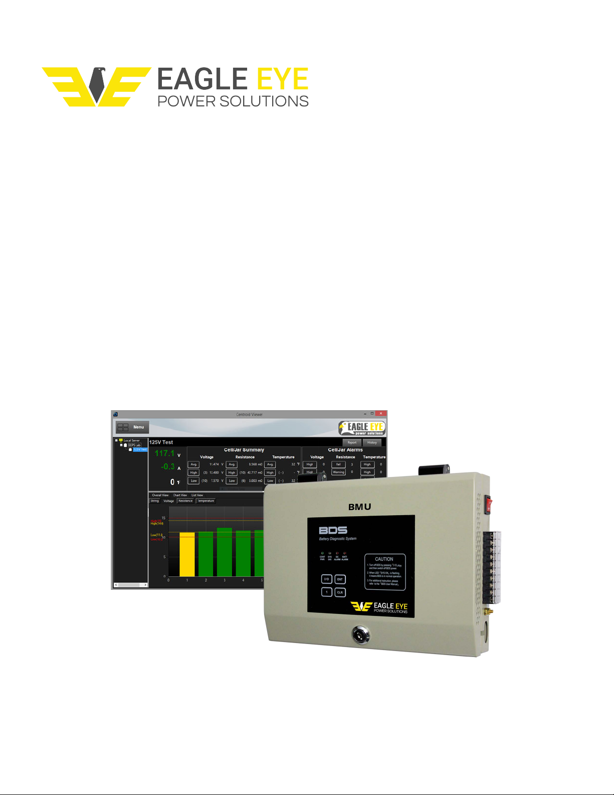
2. Product Overview
The BDS-Pro is designed to monitor and analyze the state of health of up to (24) cells by
measuring and recording:
String: Voltage & DC Float / Discharge Current
Jar/Cell: Voltage, Internal Resistance / Connection Resistance, & Temperature
All BDS-Pro solutions come complete with battery management software which allows all
battery systems to be monitored 24 hours a day, 365 days a year via remote computer(s). This
software offers comprehensive battery diagnosis and reporting capabilities to ensure the
integrity of your critical backup power system.
Alternatively, systems can be configured for Modbus communication for integration to a third-
party building management system or SCADA (supervisory control and data acquisition).
The BDS-Pro is composed of the MPU (main processing unit), Sensing Cables, Connection
Clamps, & CT.
5
BDS-Pro Installation Manual
122118
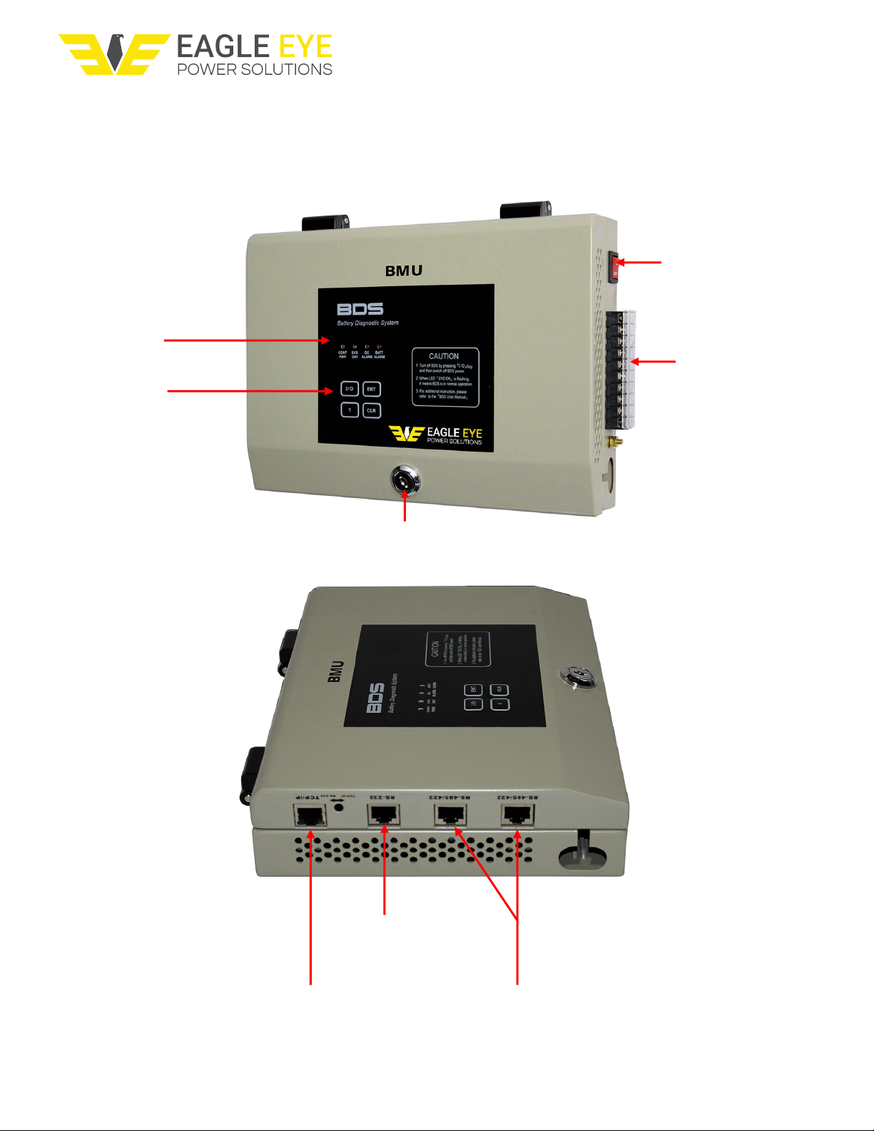
2.1 Main Processing Unit (MPU)
The MPU receives battery data and communicates with the Server.
Internal Access
Terminal Strip
(DC Power, DC
Voltage Sensing, & CT
Connections)
Power Button
Controls
System Status
Indicator Lights
TCP/IP Port
(Network Communication)
RS232 Port
(Programming &
Diagnostics)
RS485/422 Ports
(Daisy Chain
Connections)

6
BDS-Pro Installation Manual
122118

7
BDS-Pro Installation Manual
122118
2.2 Technical Specifications
Applications:
Flooded, Sealed, & NiCad battery types
Up to 24 jars / cells.
Battery Capacity Range:
Up to 6000 Ah
Cell Voltage:
1 – 16 VDC
Accuracy:
DC Voltage / Current: ±0.5% / ±1%
Temperature: ±2%
Internal Resistance: ±2%
Cell Voltage: ±1%
Resolution:
AC Voltage / Current: 0.1 V / 0.1 A
DC Voltage / Current: 0.1 V / 0.1 A
Cell Voltage: 10 mV
Internal Resistance: 0.001 Ω
Temperature: 0.5 °C
Test Speed:
3 – 4 seconds per cell
Test Load:
< 2 A per cell
Display:
LED Indicator Lights
Internal Storage:
Limited On-board memory
Measuring Interval:
Adjustable from 10 min to 24 hours (voltage & resistance)
Data Transfer:
TCP/IP, Modbus Protocol
Bandwidth Use:
< 10 Kbps
Operating Environment:
Temperature: 0 – 50 °C (32 – 122 °F)
Relative Humidity: Under 80% RH
AC Power Requirements:
110 – 220 VAC, 50/60 Hz
DC Power Requirements:
48V: 43 – 72 VDC
125V: 100 – 150 VDC
Power Consumption:
15 W
Connections:
RJ45
Dimensions L x W x D:
MPU: 231 x 270 x 55 mm (9.1 x 10.6 x 2.2 in)
8
BDS-Pro Installation Manual
122118
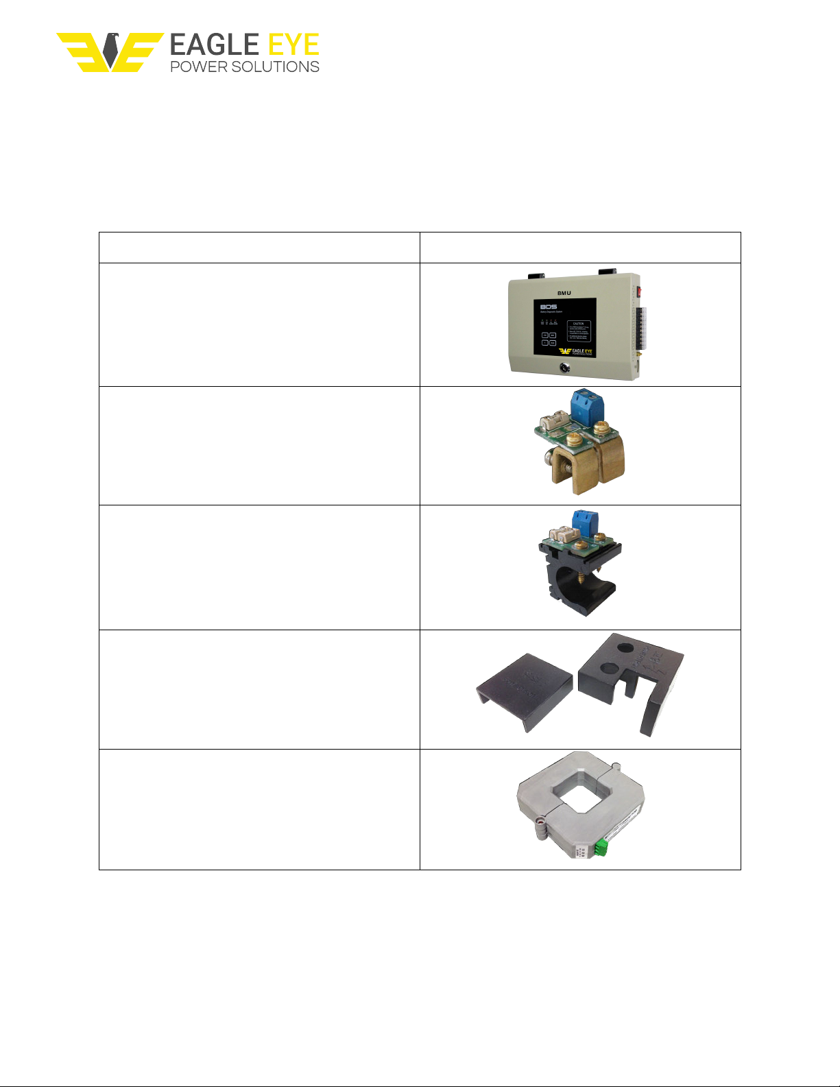
3. Parts List
The following parts come standard with each BDS-Pro package. The number and type of
connector clamps will depend on the application.
Part Name & Purpose
Picture
BDS-Pro MPU
Main processing unit for BDS-Pro system
C-Type Clamp
Clamp used for connection between batteries
with busbar inter-cell connections
O-Type Clamp
Clamp used for connection between batteries
with cable inter-cell connections
Clamp Covers: C-Type / O-Type
Placed over clamp PCB
CT Clamp
Measures DC current

9
BDS-Pro Installation Manual
122118
AC / DC Power Cable
Power cable for systems utilizing AC power
Total Voltage / DC Power Fuses
Fused lines between the Total Voltage & DC
Power cables
Total Voltage Jumpers
Allows total voltage measurement from DC
power terminations
CT Cable Harness
For connection between CT & BDS-Pro MPU
Temperature Cable Harness (4-pin)
Measures temperature of battery posts
Voltage Sensing Cable Harness (6-pin)
Measures DC voltage (Vs)
Current Sensing Cable Harness (4-pin)
Measures current (Is)
10
BDS-Pro Installation Manual
122118
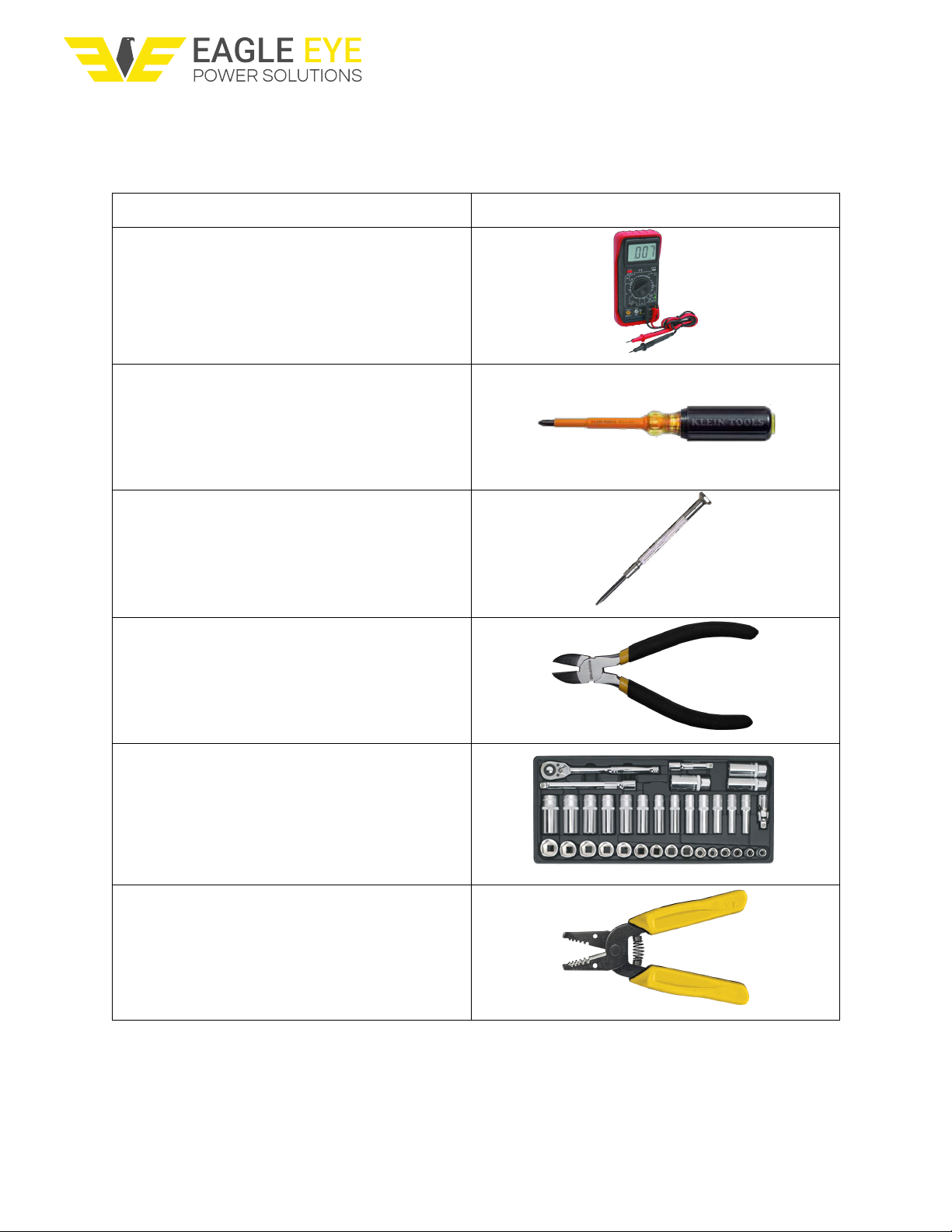
4. Installation Tools
4.1 Required Tools
Tool Name & Purpose
Picture
Multi-meter
Verification of connection voltage &
resistance
#1 Phillips Insulated Screwdriver
Tightening of O-Type/C-Type clamp screws
2/16” (2-3 mm) Flathead Screwdriver
Tightening of sensing cable
Wire Cutter
Adjustment of cable length
US or Metric Socket Set
For mounting BDS-Pro
Wire Stripper
Adjustment of cable length
Other manuals for BDS-Pro
1
Table of contents
Other Eagle Eye Measuring Instrument manuals


