Eagle Eye BTM1000 User manual

BTM-Series User Manual
Standby Battery Thermal
Safety Monitor
User
Guide
Subject
Safety
Page
2
Introduction
2
System description
3
System operation
4
Connections –Sensor
6
Connections –Monitor
7
Mounting the sensor
8
Specifications
10
1

BTM-Series User Manual
Explosiveco
ndition
SAFETY
The BTM system is a low voltage system that requires no particular safety precautions,
other than those for any 12 volt battery or system. The only precaution when installing the
sensors and monitor is that the wires should be prevented from contact with the terminals,
or any part of the high voltage/high current path of the standby battery system to which it
will be attached.
Introduction
The BTM1000 battery safety system consists of a simple thermal unit sensor which attaches
to each cell, jar or monobloc in a battery, and a system monitor which has five indicator
LEDs and two change-over (SPDT) alarm relay outputs. It is powered by a 12 volt power
supply and has no electrical connection to the battery it is monitoring, thus the voltage of the
cells or jars are not relevant to the system. The system is designed to detect over-
temperature in standby battery systems and thus assist in the prevention of a thermal
runaway situation.
Thermal runaway is a ‘positive feedback’ process in which a faulty cell or jar rises in
temperature, thus causing it to take more float current, which then causes a further rise in
temperature and so on.
Temperature
25C/77F
Time
The process often ends in an explosive rise in temperature which can destroy the cell, and
any cells adjacent to it. An example of a thermal runaway event is pictured below.
An example of a battery after thermal runaway
2

BTM-Series User Manual
US IFC608.3 (2010) requires that if a sealed battery (or batteries) operated in a single
premises contains a total of 50 gallons or over of acid the proprietor must install measures to
prevent thermal runaway.
System description
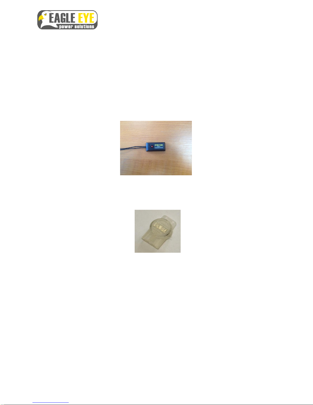
The thermal sensors are small, sealed units with two wires for connection to the adjacent
sensor and an LED which activates to indicate when the cell is in over-temperature. Each
thermal sensor is sealed to IP68 (water and dust proof) and the special gel-filled connectors
provided are also sealed against acid ingress, dust and gasses.
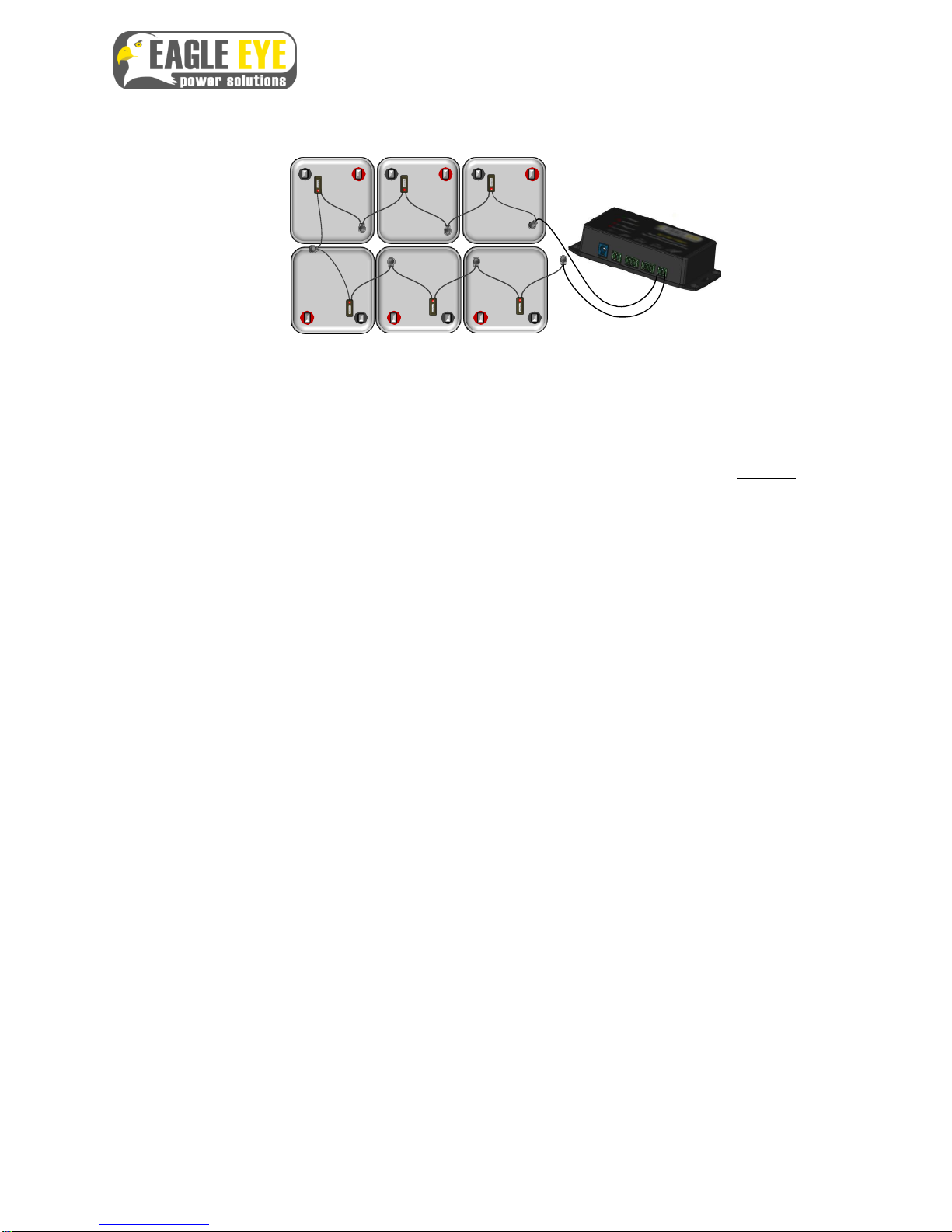
Each individual cell, monobloc or jar must have a sensor attached, to detect the
temperature of the unit. The sensors are connected in series, one wire of the sensor being
connected to a wire of the adjacent sensor.
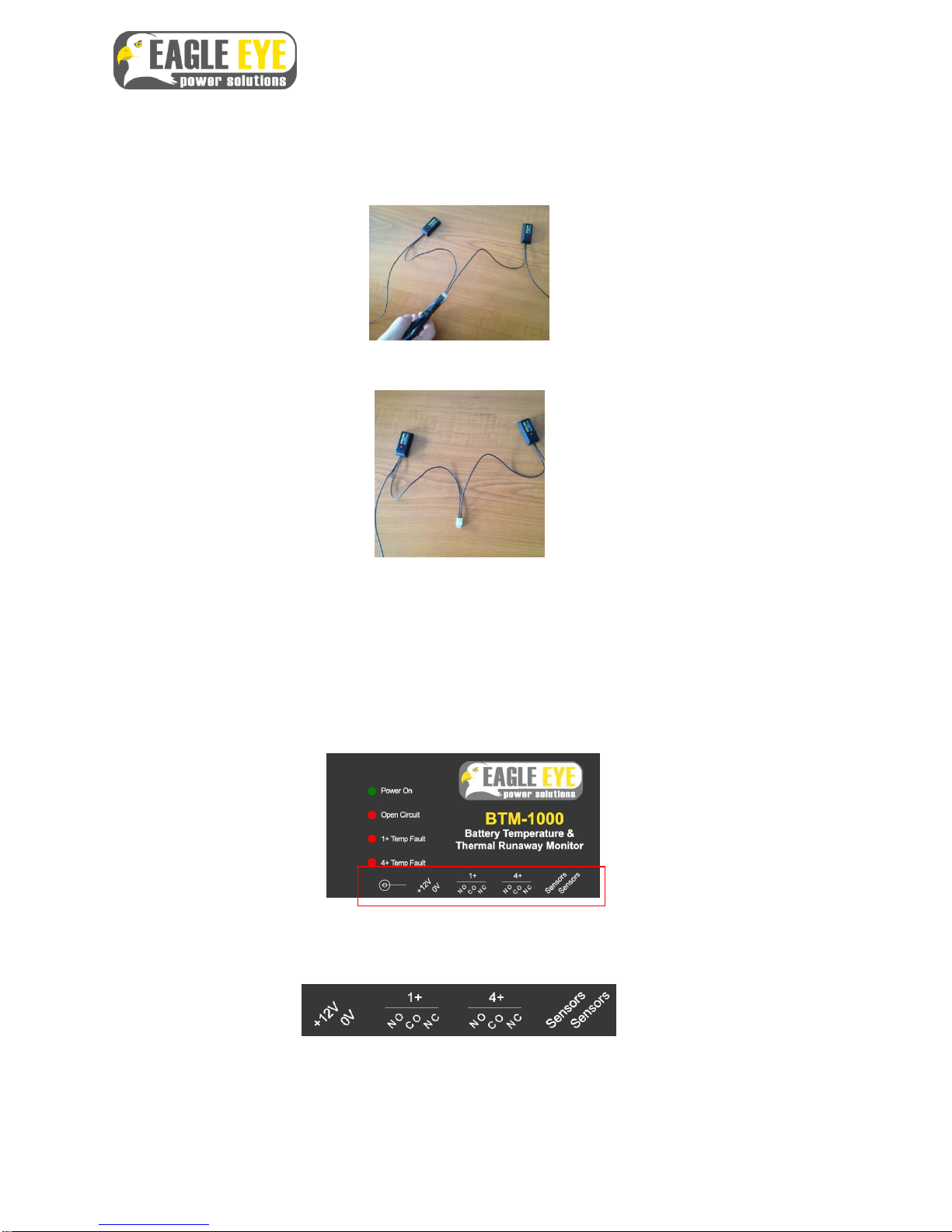
The connector (above) is an Insulation Displacement Connection (IDC), gel-filled for
protection against corrosive atmosphere and Lloyds approved as the equivalent of a
soldered joint for adverse environments.
Apart from securing the neat wall mounted monitor, the entire installation may be carried out
with a small screwdriver and a pair of side-cutting pliers. Interconnections typically take
less than 20 seconds each. Longer interconnections, such as shelf to shelf and rack to rack
are simple to accommodate with standard 20SWG cable, and the IDC connectors provided;
cable lengths, within reason, are not sensitive. Sensor installation for a 40-jar battery will
typically take less than an hour. Several batteries in the vicinity of each other may be
connected in series to the same monitor. As the system is completely electrically isolated
from the battery, voltages and polarities are not an issue.
Once the sensors are connected, the two end wires are brought back to the system
monitor and connected to the two connectors in the system monitor marked ‘Sensors’.
3

BTM-Series User Manual
The system monitor must be supplied with a DC 12 volt, 1 Amp supply, connected as
indicated below.
Number of sensors allowed on a system: Although a large number of sensors may be
used in a single circuit (over 100), the number of alarm LEDs which can illuminate in alarm
conditions is dictated by the amount of voltage available. The maximum number of sensors
which can display an illuminated LED in alarm conditions is 15.
Note: If a system has more than 15 over-temperature warnings active then the brightness of
the sensor LEDs will reduce. More over-temperatures will result in further reduction in
brightness. However the LED’s on the monitor box and the relay outputs will continue to
operate normally.
Fail-safe operation: The system is configured for ‘fail-safe’ operation; this is required by
many ultra- sensitive installations, particularly oil & gas installations, utilities, nuclear power
generating stations etc. In fail-safe operation, the alarm relay outputs are held on at all
times, except when in alarm condition. This means that if the power to the unit should fail,
the unit will always alarm, due to the output relays ‘dropping out’ and changing over.
In fail-safe operation, the relays are held ‘on’continuously, until an alarm event occurs,
when they will go to the ‘off’ condition, i.e. open.
System operation
Quick Notes:
1.
The sensors may be connected either way round, they are not polarity conscious.
2.
The relays are ‘fail-safe’, i.e., they are continuously energised, and de-energise at a fault
condition,
including loss of unit power.
3.
The microprocessor inside the unit updates change in conditions every four to five seconds.
4

BTM-Series User Manual
LEDs (monitor)
Open circuit LED on control box illuminates fully on:
1. If power is switched on with an open circuit condition
2. If power is switched on with more than four over-temperatures
3. With the unit operating, if 3 or more over temperature occur within 1 second of
the first over-temperature
With one over-temperature on one sensor the following will be indicated:
1. The 1+ LED on the control box with flash on/off in a period of 1/second
2. The LED on the sensor with the over-temperature will flash from low to high
intensity at a rate of 1/second
With over-temperatures on 4 or more sensors the following be indicated:
1. The 1+ LED and the 4+ LED will flash alternatively at a rate of 1/second
2. The LED’s on the sensors with the over-temperatures will flash from low to high
intensity at a rate of 1/second
The operation of the relays indicates the following:
1. Relay 1+ off (CO –NC, short), Relay 4+ off (CO –NC, short)
a. Four or more over temperatures exist OR
b. No power to the control box –the green LED will be off.
2. Relay 1+ off (CO –NC, short), Relay 4+ on (CO –NC, open)
a. Over temperature on one sensor
3. Relay 1+ on (CO –NC, open), Relay 4+ off (CO –NC, short)
a. Open circuit connection
5

BTM-Series User Manual
General information:
In the event of one or more Jars exceeding critical temperature, or a break in the sensor circuit,
the monitor warning relay activates and the warning LED on the monitor is illuminated; at the
same time a bright LED flashes on the sensor attached to the over-temperature battery jar,
indicating the source of the fault. Should more than 4 Jars exceed critical temperature, the
system-critical alarm relay activates, warning of a serious situation in the battery as a whole.
In the unlikely event of the sensors being connected after power up the following will occur after
illumination of the open circuit LED
1. No over-temperature, the open circuit LED will go out
2. 4+ over-temperatures, the open circuit LED will stay on and the sensors that are
over- temperature will show low intensity for 4 seconds then flash high intensity for 1
second. This will be repeated every 5 seconds
3. 1+ over-temperature, the open circuit LED will go out and the 1+ LED will flash from
low to high intensity at a rate of 1/second
Connections -
sensor
The sensor has only two wires. They may be attached to the adjacent sensor, or to the
monitor in either orientation, the sensors are designed not to be sensitive to the polarity of
the electricity of the circuit.
The connectors are gel-filled IDC (see description above) and the connecting wires should be
pushed into the connector without first stripping (removing the insulation from) the ends of the
wire.
6

BTM-Series User Manual
When both wires are firmly inserted into the connector, making sure that both reach the stop
at the far end, the top and bottom of the connector should be compressed by a dedicated
compression tool*, or, if this tool is not available, providing care is taken a suitable pair of
pliers may be used.
This forms a secure, protected joint between the two sensors.
* An Example of the correct crimping tool can be found in the RS Components catalogue titled ‘Splice plier crimp
tool’. RS stock number: 238-9434 or CableOrganiser.com stock number PL-12100. Others are available.
Connections - monitor
The input/output connections of the monitor are shown on the label on the top of the enclosure:
And on the long side of the enclosure, above the connections themselves:
7

BTM-Series User Manual
12 volt supply in; either the
barrel connector or the Molex
connector may be used
(not both) Alarm relay output
for one or more cells
in over-temperature
Alarm relay output
for fouror more cells
in over-temperature
Sensor circuit connections
(2) not polarity sensitive
Mounting the sensor
The sensor has a high reliability sticky pad on its base; this is covered by a clear plastic
overlay.
The area on the cell on which the sensor is to be mounted should be cleaned of all dust and
residue. Then the plastic protection should be peeled off the sensor and the sensor placed in
position on the cell.
It is suggested that in flooded cells the sensor should be sited near the top of the enclosure,
but below the level of the electrolyte. In starved electrolyte batteries (VRLA, SLA, Gel) the
sensor can be placed in any available space, however the top of the unit is optimum.
8

BTM-Series User Manual
After the sensor is placed in the chosen position a firm pressure should be applied, to
initiate the bond. The bond will increase over the following 24 hours.
9

BTM-Series User Manual
Specification
Thermal sensor: Totally enclosed, activation temperature 35°C (95F), +/- 3°C (5°F).
Environmental: sealed IP67
Reinstatement temperature: 2°C (3.5°F) below activation
temperature Module and connections insulated to >2500V.
Connection cable: UL1007
Sensor Interconnections: Gel-filled IDC ‘cold-weld’; sealed against dust and gasses;
solvent/acid resistant; UL listed cat. 5. Interconnection strength >90% of wire breaking
strength
Connection wire: UL compliant
Monitor: Backplate mounted; Input power 12 volts DC, 0.1A; output: (on alarm) 2 x relays,
SPDT volt-free contact (1+ units over-temperature, and 4+ units over-temperature). Monitor
dimensions: H84 x W40 x D77mm
Output relay contact ratings: 7A at 240VAC, 10A at 120VAC, isolation 1K5V
General Compliance: UL, CE.
Sensor dimensions:
38mm
12mm 300mm
10mm + LED
19.7mm
10
Table of contents
Other Eagle Eye Measuring Instrument manuals