Eagle EVR-100 User manual

EVR-100
VHF Radio
Operation Instructions
www.eaglesonar.com
Pub. 988-0158-031

Copyright © 2007 Navico
All rights reserved.
Eagle® is a registered trademark of Navico
No part of this manual may be copied, reproduced, republished, transmitted or
distributed for any purpose, without prior written consent of Eagle Electronics.
Any unauthorized commercial distribution of this manual is strictly
prohibited.
Eagle Electronics may find it necessary to change or end our policies,
regulations, and special offers at any time. We reserve the right to do so without
notice. All features and specifications subject to change without notice. All
screens in this manual are simulated. On the cover: EVR-100 shown. Other
models covered in the manual are similar.
For free owner’s manuals and the most current information on this product, its
operation and accessories, visit our web site: www.eaglesonar.com
Eagle Electronics
P.O. Box 669
Catoosa, OK USA 74015
Printed in China.
IMPORTANT SAFETY INFORMATION
Please read carefully before installation and use.
CAUTION
!
!
CAUTION
DANGER
WARNING
This is the safety alert symbol. It is used to alert you to potential personal
injury hazards, Obey all safety messages that follow this symbol to
avoidpossible injury or death.
CAUTION
!
!
CAUTION
DANGER
WARNING
WARNING indicates a potentially hazardous situation which, if not avoided,
could result in death or serious injury
CAUTION
!
!
CAUTION
DANGER
WARNING
CAUTION indicates a potentially hazardous situation which, if not avoided,
could result in minor or moderate injury.
CAUTION
!
!
CAUTION
DANGER
WARNING
CAUTION used without the safety alert symbol indicates a potentially
hazardous situation which, if not avoided, may result in property
damage.

EAGLE EVR-100 Operation Instructions 3
Table of Contents
Introduction.............................................................................................................................................4
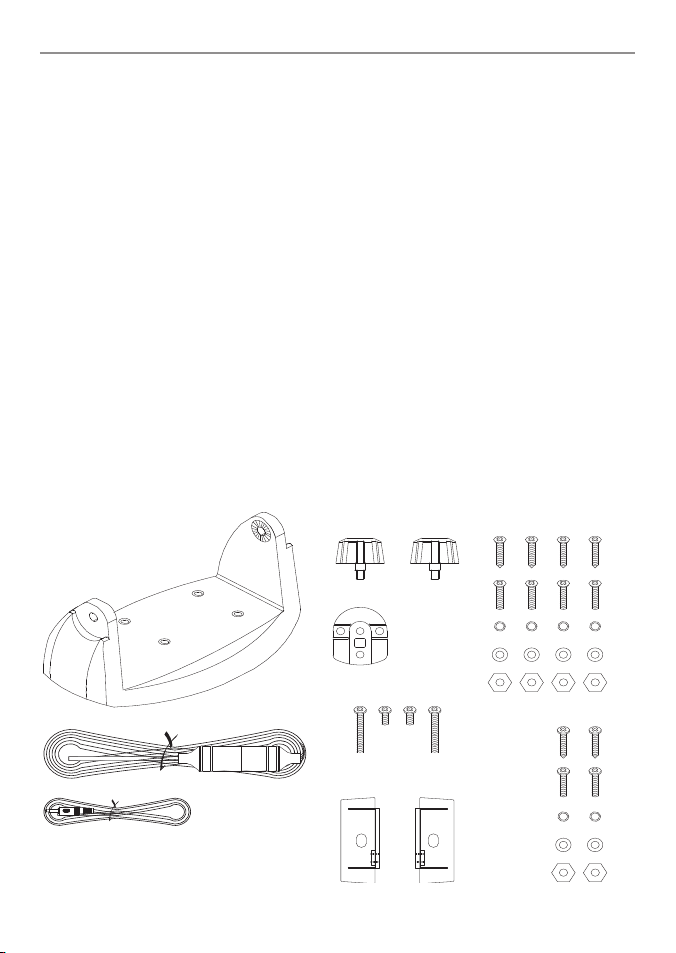
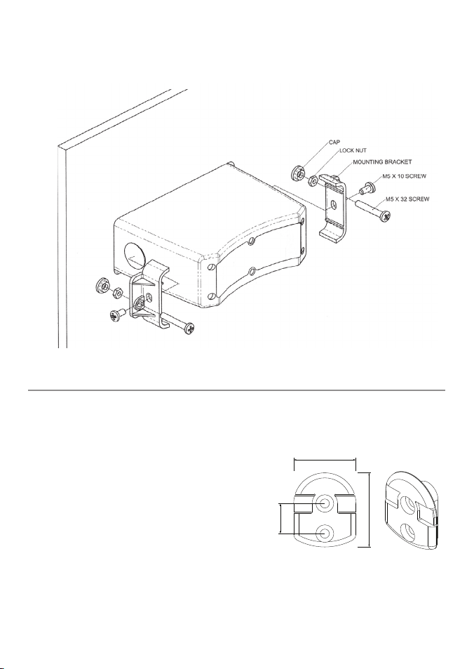
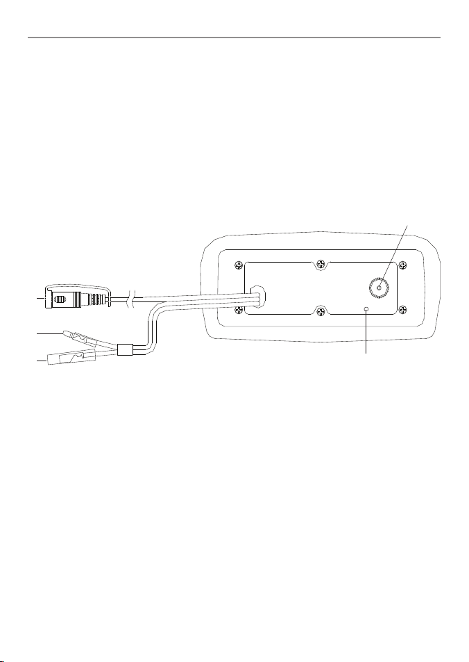
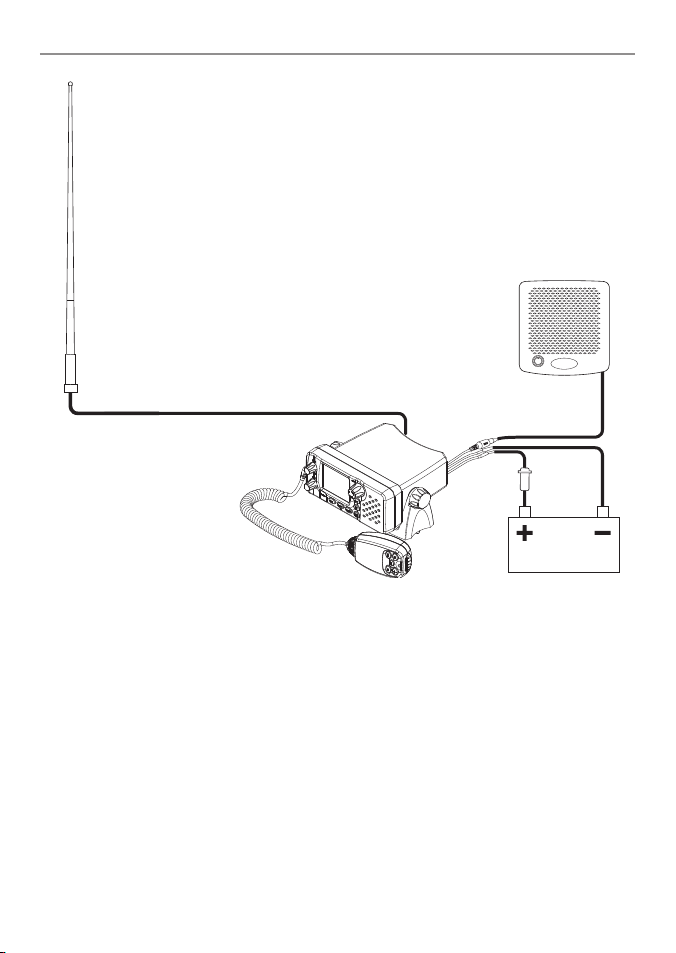
Installation ..............................................................................................................................................5
Display ................................................................................................................................................... 11
Basic Operation and Key Functions.......................................................................................................... 12
Radio Operation ..................................................................................................................................... 14
Turning Your Radio On/Off ..........................................................14
Adjusting Squelch ..................................................................14
Selecting High/Low Power ..........................................................14
Selecting Channels .................................................................14
Transmitting and Receiving .........................................................14
Scanning Features ..................................................................15
Monitor Modes (Dual Watch) ........................................................15
NOAA Weather Channels ............................................................16
NOAA Weather Alert ................................................................16
Resetting your Radio ................................................................16
Appendix A - Technical Specifications...................................................................................................... 17
Appendix B - Troubleshooting................................................................................................................. 18
Appendix C - Frequency Charts ................................................................................................................ 19
International Channel Chart .........................................................19
USA Channel Chart ..................................................................21
CANADA Channel Chart .............................................................23
WEATHER Channels .................................................................25
Eagle Warranty....................................................................................................................................... 26
How to Obtain Service . . ........................................................................................................................ 27

EAGLE EVR-100 Operation Instructions4
Introduction :
Congratulations on your purchase of an Eagle EVR-100 marine band VHF radio. Designed for
international operation, allows you to transmit and receive on all international channels in the
VHF marine band, as assigned by the International Union (ITU). The EVR-100 is approved with
commercial-grade standards to give you clear, reliable communication.
NOTE: According to WEEE regulations, the user should not dispose the product when damaged,
but rather send it back to Eagle for disposal. Refer to How to Obtain Service section for
instructions to contact Eagle.
Your radio has the following features:
lſ Prominent channel display
lKeypad and LCD backlighting for easy night-time use
lWaterproof and submersible to comply with JIS-7
lChoice of High or Low (7 W or 1 W) transmission power
lTop centered PTT button for comfortable left- or right-handed use
lPowerful 4 W external audio output
lAccess to all currently-available marine VHF channel bands (USA, Canada, International)
including Weather channels where available
lSpecial CH16/9 key for quick access to the priority (international distress) channel
lSpecial 3CH key to select your three favorite channels
lWeather alert facility where available
lSquelch Adjustment to help eliminate noise between transmissions
lBattery Level - displays the battery voltage

EAGLE EVR-100 Operation Instructions 5
This Eagle radio allows you to make a maritime distress call to facilitate search and rescue. To
be effective as a safety device, this radio must be used only within the geographic range of a
shore-based VHF marine Channel 16 distress and safety watch system. The geographic range
may vary but under normal conditions is approximately 20 nautical miles.
Installation Options
There are two ways to install the radio. You can choose:
• a deck or overhead mounted gimbal installation. The reversible mounting gimbal is fixed to to a
suitable site and the radio is placed into it.The radio can be removed for storage and the viewing
angle can be adjusted.
• a recessed installation. The radio is recessed into a cavity cut into a bulkhead. The radio fixture is
permanent and the viewing angle cannot be adjusted.
Location Requirements
Please check these BEFORE doing any cutting or drilling.
Whichever installation method you choose, ensure that the chosen location:
• is at least 3' (1 m) from the antenna
• allows easy connection to (at least) a 10 Amp fused 13.6 V DC electrical source and the
antenna
• is at least 1.5' (45 cms) from the compass to avoid creating magnetic deviation of the compass
during radio operation
• has a suitable space close by for installing the microphone bulkhead mount
• provides easy access to the controls on the front panel
• provides reasonable access to the wiring at the back of the radio
The VHF has a large LCD screen
with an optimum viewing angle
of approx. +/-20 deg. Ensure the
chosen location provides a suitable
view of the display. Ideally, the user
should be directly in front of the
display or no more than +/-20 deg
from the front of the display.
Note: If unsure, temporarily power
up the radio and check for a
suitable location.
20˚
20˚
20˚
20˚
Side
Top
Installation:

EAGLE EVR-100 Operation Instructions6
Checklist
The following items should be supplied in the box. Check before starting the installation and con-
tact your dealer if an item is missing.
NOTE: An antenna is NOT provided. Consult your Eagle dealer for advice if necessary.
1
3
2
5
4
6
7
8
9
10
11
12
13
14
15
16
17 & 18
1. Mounting gimbal for the VHF radio
2. Power supply cable with inbuilt 3 Amp
fuse
3. External speaker connection cable with
white (+) wire and black (-) wire
4. Two mounting knobs
5. Microphone bulkhead mount
6. Four self-tapping screws for the mounting
gimbal
7. Four flat screws for the mounting gimbal
8. Four spring washers for the mounting
gimbal
9. Four plain washers for the mounting
gimbal
10. Four nuts for the mounting gimbal
11. Two self-tapping screws for the
microphone bulkhead mount
12. Two flat screws for the microphone
bulkhead mount
13. Two spring washers for the microphone
bulkhead mount
14. Two plain washers for the microphone
bulkhead mount
15. Two nuts for the microphone bulkhead
mount
16. Two flush-mount brackets for recessed
installation
17. Two M5x32 screws for recessedinstallation
18. Two M5x10 screws for recessed installation
19. Two plastic stoppers for the recessed
installation (not pictured)
20. Installation template (not pictured)
21. One 3 Amp spare fuse (not pictured)
in case of accidental reverse of battery
polarity
22. Base unit and microphone (not pictured)

EAGLE EVR-100 Operation Instructions 7
Gimbal Installation
1. Hold the mounting gimbal at the chosen location and use a soft pencil to mark the screw hole
positions onto the mounting surface.
2. If you can’t reach behind the mounting surface to attach the nuts, use the self-tapping screws
instead of the flat screws shown in the picture. If you’re drilling into fiberglass, use a drill bit
smaller than 3/16” (5mm) to drill the pilot holes.
Otherwise, drill the four screw holes where marked, using a 3/16” (5mm) drill bit. Drill com-
pletely through the mounting surface.
3. Use a Philips screwdriver and the set of four flat screws, spring washers, plain washers, and nuts
to attach the mounting gimbal to the location site.
4. Slide the radio into the mounting gimbal.
5. Insert the two mounting knobs through the holes and tighten them suciently to hold the
radio at the desired viewing angle.
Change the Viewing Angle
The viewing angle on the gimbal mount has a 20º tilt range. To change the current viewing angle
on the gimbal mount:
1. Support the radio, then cautiously loosen the mounting knobs until the radio can be moved.
2. Re-position the radio then tighten the mounting knobs again.
Recessed Installation
1. Tape the installation template onto the chosen location site.
2. Cut out the area marked by the solid dark line. (The dashed line indicates the total area that will
be ed by the radio fascia after installation.)
3. Remove the installation template and slide the radio into the cavity.
4. Working from the rear of the bulkhead, align the racheted outstand on each side of the radio
with the central hole in each mounting bracket.

EAGLE EVR-100 Operation Instructions8
5. Use the two short M5x10 screws to screw the mounting brackets to the sides of the radio.
6. Screw each M5x32 screw through the screw hole in the mounting bracket, then attach the
stopper. If your bulkhead exceeds 0.51” (13mm), the stopper can be discarded if necessary.
7. Tighten the M5x32 screws until the radio is held rmly against the rear of the bulkhead.
Install the Microphone Bulkhead Mount
1. Hold the microphone bulkhead mount at the
chosen location and use a soft pencil to mark
the screw hole positions on the mounting
surface.
Ensure that the microphone curly cable will
comfortably reach this location BEFORE you drill.
2. Drill the two pilot screw holes where marked.
3. Use a short length Philips screwdriver and the
set of two flat screws, spring washers, plain
washers, and nuts to secure the microphone
bulkhead mount at the location
site.
4. Hang the microphone on its mount.
MM
MM
MM
MM
MM
MM

EAGLE EVR-100 Operation Instructions 9
Connect the Radio Cables
The connectors are on the rear of the base unit, as follows:
1. External Speaker connector. Plug the external speaker cable jack into the connector BEFORE
powering on the radio. Use a 4 Ohm 4 Watt external speaker.
2. RED Power wire. Connect this to the POSITIVE (+) battery terminal. Check that a 3 Amp fuse is
installed on this power cable close to the battery.
3. BLACK Power wire. Connect this to the NEGATIVE (-) battery terminal.
4. ANT. A radio antenna is not supplied. A suitable radio antenna must be mounted and
connected before operating the EVR-100 radio. Consult your dealer for advice if necessary.
5. GND. A ground connection is not usually required.
1
2
3
4
5

EAGLE EVR-100 Operation Instructions10
The Completed Installation
Battery
VHF Antenna
Antenna connection cable
External
speaker
BLACK
power
cable
Fuse
on RED
power
cable
External speaker
connection
cable
Base unit
with microphone*
* Actual model may differ from that shown

EAGLE EVR-100 Operation Instructions 11
Display
LCD symbols and Meanings
Symbol Meaning
TX Transmitting.
HI LO Transmission power. High (HI) 7W or Low (LO) 1W.
BUSY Receiver busy with an incoming signal.
WX Weather channel.
WX ALT Weather Alert. Alarm beeps will sound.
PRI Priority channel is selected.
SCAN Scanning channels.
DW Dual Watch mode.
ALL ALL channels scan mode.
C1 C2 C3 Shows which of the 3 favourite channels, if any, are selected, otherwise
blank.
(small)
(large) Channel selected.
UIC Selected Channel bank for VHF radio operations and regulations (USA,
International, Canada)
Low Battery warning (activates at 10.5V)
Channel is temporarily deleted from the ALL SCAN operation. D Indicates
a Duplex channel is selected, otherwise, blank for Simplex operation.
A B Channel sux, if applicable.
D Duplex operation, otherwise, blank for simplex operation.

EAGLE EVR-100 Operation Instructions12
Basic Operation and Key Functions
Key Function
VOL/PWR Volume and Power. Turn clockwise to power on. Continue to turn until a
comfortable volume is reached. VOL/PWR will also adjust the settings of an external
speaker, if connected
SQL Squelch or Threshold Level. Sets the threshold level for the minimum receiver
signal. Turn fully counterclockwise until random noise is heard, then turn slowly
clockwise until the random noise disappears. Make another 1/4 turn clockwise for
best reception in open sea conditions.
16/9 Priority Channel. Also on the microphone. Press to cancel all other modes and to
tune into the priority channel. Press again to return to your original channel.
The default is Channel 16. To make Channel 09 the priority channel, hold down 16/9
until a beep sounds and 09 is displayed.
WX Weather Channel. In USA and Canadian waters, press to hear the most recently
selected weather station. The WX symbol is displayed on the LCD.
Press + CH - to change to a different weather channel. Press WX again to return to
the most recent channel.
If the weather alert mode (ALT) is ON and an alert tone of 1050Hz is broadcast from
the weather station, it is picked up automatically and the alarm sounds. Press any key
to hear the weather alert voice message.
UIC Channel Bank. Press to toggle between USA, International or Canadian channel
banks. The selected channel bank is displayed on the LCD along with the last used
channel. All the channel charts are shown in Appendix.
3CH +/- Three Favourite Channels. Also on the microphone. Press to toggle between your
favourite channels. The C1, C2, or C3 symbol appears on the LCD to show which
favourite channel is selected.

EAGLE EVR-100 Operation Instructions 13
To scan only one of your favourite channels, press 3CH then immediately press
and release SCAN. If you want to scan all three favourite channels, press 3CH then
immediately press and hold SCAN.
To add a favourite channel for the first time, select that channel then hold 3CH
to store it in the CH1 location. Repeat the procedure to store two more favourite
channels in the CH2 and CH3 locations respectively.
If you try and add another favourite channel it will overwrite the existing CH1. CH2
and CH3 remain unless you delete them.
To delete a favourite channel, select that channel then hold down 3CH until the C1,
C2 or C3 symbol disappears on the LCD.
SCAN Scan. Press to scan between your current channel and the priority channel in DUAL
WATCH mode. The weather channel is also scanned if the weather alert mode (ALT)
is ON.
Hold down SCAN to enter ALL SCAN mode where the priority channel is checked
every 1.5 seconds.
When a signal is received, scanning stops at that channel and BUSY appears on the
screen. If the signal ceases for more than 3 seconds, the scan restarts.
Press SKIP to temporarily skip over an “always busy” channel when in ALL SCAN
mode and resume the scan. An is shown on the screen to designate a skipped
channel. Note that it is not possible to skip over the priority channel.
Press SCAN again to stop at the current channel.
+ CH - Channel Select. Also on the microphone. The current channel is shown on the
screen in BIG digits with an appropriate designator suffix A or B in small letters below
the channel number.
Press + CH - to step through the available channels one at a time, or hold down to
scroll rapidly through all the available channels. See Appendix for a listing of channel
charts.
Backlight switch. Press to turn on the backlighting, press again to turn off
Battery Level Check. Press to display the battery voltage level. The battery voltage
level will be displayed for 5 seconds before returning back to the previous screen.
SKIP Remove from ALL scan. Press to temporarily remove (SKIP) the channel from ALL
SCAN. The channel will be marked with an . Press again to cancel the channel
SKIP.
H/L Transmission Power. On the microphone ONLY. High (HI) 7W or Low (LO) 1W. Press
to toggle between high or low transmission power for the entire channel bank. The
HI or LO selection is shown on the LCD.
Some channels allow only low power transmissions. Error beeps will sound if the
power transmission setting is incorrect.
Some channels allow only low power transmissions initially, but can be changed
to high power by holding down H/L and PTT at the same time. See Appendix for a
complete listing of channel charts.
PTT Push To Talk. On the microphone ONLY. Push to start transmitting.

EAGLE EVR-100 Operation Instructions14
Turning Your Radio On/Off
Rotate VOL/PWR knob to turn the radio on or off. Rotate to adjust the volume to a comfortable
level.
Adjusting Squelch
Squelch is used to eliminate static and background noise and allows for silent operation of your
radio until a transmission is received. If the squelch is too high, only the strongest transmissions
can be heard, and when too low, intermittent static and noise are heard.
To set Squelch:
1. Turn SQL knob fully counter-clockwise. You will hear a lot of static noise.
2. Then turn SQL knob clockwise slowely until the static noise stops, this is the correct position
for the SQL knob.
Selecting High/Low Power
Press and release the H/L key on the microphone to toggle the transmit power between high and
low. When the unit is operating at low power, “Lo” appears on LCD and “Hi” appears on LCD when
operating at high power.
Some channels allow only low power transmissions. Error beeps will sound if the power
transmission setting is incorrect. Some channels allow only low power transmissions initially, but
can be changed to high power by holding down H/L and PTT at the same time. See Appendix for
a complete listing of channel charts.
Selecting Channels
To select a channel:
Use the + CH - key to find a channel. Stop when you find the desired channel.
NOTE: Not all channel numbers are available in INT bands, see marine Channel charts at the back
of this manual.
Transmitting and Receiving
Press and hold the Push-To-Talk (PTT) key to transmit on the selected channel, then release to
receive. The TX indicator appears while transmitting.
Radio Operation

EAGLE EVR-100 Operation Instructions 15
Scanning Features
Your radio is equipped with 2 types of scan options: All Scan, 3CH Scan (Favourite Channel
Scan). If there are no channels added as favourite channels, the default is All Scan. This function
automatically searches for transmissions on the channel being scanned. If a signal is received, the
scan stops on the receiving channel as long as it is present and the SCAN indicator flashes. If the
signal is lost for 3 seconds, the radio resumes scanning.
All Scan
Press and hold the SCAN key for 3 seconds to activate the All Scan function. The SCAN and ALL
indicator appears on the LCD during All Scan. In All Scan mode, all channels in the channel set are
scanned in sequence except the channel set as SKIP channel using SKIP function. After the last
channel number has been scanned, the cycle repeats. Press SCAN key again to terminate the
SCAN mode.
To Skip a channel in ALL scan
Press SKIP to temporarily remove (SKIP) the channel from ALL SCAN. The channel will be
marked with an . Press again to cancel the channel SKIP.
3CH Scan (Favourite Channels Scan)
Press 3CH key when there is at least one favourite channel saved in memory.
Press and hold the SCAN key for 3 seconds to start 3CH Scan , the SCAN indicators appear on the
LCD. Only the favourite channels and priority channels (CH16) are scanned in sequence.
Your radio can store up to three favourite channels. Quick press of the 3CH key will access the
stored favourite channels directly (shortcut).
To Add Channels to 3CH List
During normal operation mode, use the + CH - keys to select the desired channel for
programming.
Press and hold the 3CH key for 3 seconds. The "C1" icon appears to indicate the current
channel has been saved in first favourite channel. Repeat for the second and third favourite
channels as C2 and C3 respectively.
To Delete Channels from 3CH List
Select the favourite channel to be deleted using the + CH - keys, or repeated quick press of
the 3CH key. Press and hold the 3CH key until the “Cn” icon disappears.
Monitor Modes (Dual Watch)
Quick press the SCAN key to activate the Dual Watch mode. The "DW" indicator appears on the
LCD. Dual Watch monitors the current working channel and Channel 16 in sequence. WX ALT is
also scanned in this mode if set. The watch is halted when activity is detected on a monitored
channel. Press SCAN key or PTT to terminate Dual Watch and return to the previous working
channel.

EAGLE EVR-100 Operation Instructions16
NOAA Weather Channels
To receive a NOAA (National Oceanic and Atmospheric Administration) weather channel, press the
WX key. The transceiver will go to the last selected weather channel.
Press the + CH - keys to scroll through the available WX channels.
To exit from the NOAA weather channels, press the WX key to terminate WX mode and return to
the previous working channel, or press 16/9 to access the priority channels.
NOAA Weather Alert
In the event of extreme weather disturbances, such as storms and hurricanes, the NOAA sends
a weather alert accompanied by a 1050 Hz tone and subsequent weather report on one of the
NOAA weather channels.
When the Weather Alert feature is enabled, your radio is capable of receiving this alert.
In the Weather channel, press and hold WX button for 3 seconds to active the Alert function -
“ALT” will appear on the LCD. To cancel the alert function, Press and hold WX button for 3 seconds
again, the “ALT” icon will disappear from the LCD.
Note: If Weather Alert mode is selected (WX ALT icon displayed in WX mode), Weather Alert will
continue to be monitored even when in normal mode (non-Wx channels) is selected.
Resetting your Radio
Your radio can be reset to factory defaults. A factory reset clears the following user settings:
lſ favourite channels,
lſ current channel,
lſ channel bank.
To perform the reset:
1. Turn the radio OFF.
2. Simultaneously press and hold the SCAN &UIC buttons.
3. Continue to hold the keys until “CC” appears on the LCD. Release the keys to finish the reset
process. The LCD switches to CH16 and USA channel bank is selected..

EAGLE EVR-100 Operation Instructions 17
Appendix A - Technical Specifications
GENERAL
Power Supply: 13.8V DC.
Current drain:
Transmit 1.5 A at 7 W Tx / 0.6A at 1W Tx
Receive Less than 250mA in standby
Useable channels: International, USA, Canada, Weather (country specific)
Mode: 16K0G3E (FM)
PHYSICAL
LCD display (viewing): 41(H) x 53(W) mm
Backlight control: Yes (On/Off )
Antenna connector: SO-239 (50 ohm)
Temperature Range: -17ºC to +50ºC
Waterproof: JIS-7
Dimensions: 161(W) x 75(H) x 147(D) mm - without bracket
Weight: 0.87kg with microphone
Frequency stability: +/- 10ppm
Frequency control: PLL
GPS/NMEA input: No
Comm port: n/a
DSC: No
FEATURES
Flush Mount kit: Yes
Local/Distant control: No
Position polling: No
Group Call: No
Channel Naming: No
Dual watch, Favourite
channel scan, All scan: Yes
TRANSMITTER
Frequency: 156.025 - 157.425MHz
Output power: 7 W / 1 W selectable
Transmitter protection: Open / short circuit of antenna
Max Freq deviation: +/- 5kHz
Spurious & harmonics: better than 2.5µ W
Modulation distortion: Less than 4%@ 1kHz for a +/-3kHz deviation
RECEIVER
Frequency: 156.025 - 163.275 MHz
12dB SINAD sensitivity: 0.25uV
20db SINAD sensitivity: 0.35uV
Adjacent CH selectivity: more than 65db
Spurious response: more than 65 db
Intermodulation Rejection ratio: more than 65 db
Residual Noise level: more than -40 db unsquelched
Audio output power: 2 W (with 8 ohm at 10% distortion)
4 W with 4 ohm external speaker
Compass safe distance: 0.5 m (1.5’)
Specifications are subject to change without notice.

EAGLE EVR-100 Operation Instructions18
Appendix B - Troubleshooting
1. The transceiver will not power up.
A fuse may have blown OR there is no voltage getting to the transceiver.
a) Check the power cable for cuts, breaks, or squashed sections.
b) After checking the wiring, replace the 3 Amp fuse (1 spare fuse is supplied).
c) Check the battery voltage. This must be greater than 10.5V.
2. The transceiver blows the fuse when the power is switched on.
The power wires may have been reversed.
a) Check that the red wire is connected to the positive battery terminal, and the black wire is
connected to the negative battery terminal.
3. The speaker makes popping or whining noises when the engine is running.
Electrical noise may be interfering with the transceiver.
a) Re-route the power cables away from the engine.
b) Add a noise suppressor to the power cable.
c) Use resistive spark plug wires and/or use an alternator whine filter
4. No sound from the external speaker.
a) Check that the external speaker cable is physically connected.
b) Check the soldering of the external speaker cable.
5. Transmissions are always on low power, even when high (HI) power is selected.
The antenna may be faulty.
a) Test the transceiver with a different antenna.
b) Have the antenna checked out.
6. Battery symbol is displayed.
The power supply is too low or too high.
a) Check the battery voltage. This should be at least 10.5V ± 0.5V DC.
b) Check the alternator on the vessel.

EAGLE EVR-100 Operation Instructions 19
International Channel Chart
CH TX RX MODE TRAFFIC TYPE SHIP SHIP REMARK
(MHz) (MHz) TO TO
SHIP SHORE
01 156.050 160.650 D Public Correspondence No Yes
02 156.100 160.700 D Public Correspondence No Yes
03 156.150 160.750 D Public Correspondence No Yes
04 156.200 160.800 D Port Operations No Yes
05 156.250 160.850 D Port Operations, Selected VTS Areas No Yes
06 156.300 156.300 S Inter-ship Safety Yes No
07 156.350 160.950 D Port Operations No Yes
08 156.400 156.400 S Commercial (inter-ship only) Yes No
09 156.450 156.450 S Recreational Calling Channel Yes Yes
10 156.500 156.500 S Commercial Yes Yes
11 156.550 156.550 S Commercial, VTS in Selected Areas Yes Yes
12 156.600 156.600 S Port Operations, Selected VTS Areas Yes Yes
13 156.650 156.650 S Inter-ship Navigation Safety (bridge-to bridge) Yes No
14 156.700 156.700 S Port Operations, Selected VTS Areas Yes Yes
15 156.750 156.750 S Port Operations Yes Yes 11W only
16 156.800 156.800 S International Distress, Safety, and Calling Yes Yes
17 156.850 156.850 S State Controlled Yes Yes 11W only
18 156.900 161.500 D Port Operations No Yes
19 156.950 161.550 D Commercial No Yes
20 157.000 161.600 D Port Operations No Yes
21 157.050 161.650 D Port Operations No Yes
22 157.100 161.700 D Port Operations No Yes
23 157.150 161.750 D Public Correspondence No Yes
24 157.200 161.800 D Public Correspondence No Yes
25 157.250 161.850 D Public Correspondence No Yes
26 157.300 161.900 D Public Correspondence No Yes
27 157.350 161.950 D Public Correspondence No Yes
28 157.400 162.000 D Public Correspondence No Yes
60 156.025 160.625 D Public Correspondence No Yes
61 156.075 160.675 D Port Operations No Yes
62 156.125 160.725 D Port Operations No Yes
63 156.175 160.775 D Port Operations No Yes
64 156.225 160.825 D Public Correspondence No Yes
65 156.275 160.875 D Port Operations No Yes
Appendix C - Frequency Charts

EAGLE EVR-100 Operation Instructions20
66 156.325 160.925 D Port Operations No Yes
67 156.375 156.375 S Commercial, bridge-to-bridge Yes No
68 156.425 156.425 S Boat Operations, Recreational Yes No
69 156.475 156.475 S Port Operations Yes Yes
70 156.525 156.525 Digital Selective Calling - DSC ------ ------ 2
71 156.575 156.575 S Port Operations Yes Yes
72 156.625 156.625 S Inter-ship Yes No
73 156.675 156.675 S Port Operations Yes Yes
74 156.725 156.725 S Port Operations Yes Yes
77 156.875 156.875 S Inter-ship Yes No
78 156.925 161.525 D Non-Commercial No Yes
79 156.975 161.575 D Commercial No Yes
80 157.025 161.625 D Commercial No Yes
81 157.075 161.675 D Port Operations No Yes
82 157.125 161.725 D Port Operations No Yes
83 157.175 161.775 D Public Correspondence No Yes
84 157.225 161.825 D Public Correspondence No Yes
85 157.275 161.875 D Public Correspondence No Yes
86 157.325 161.925 D Public Correspondence No Yes
87 157.375 161.975 D Public Correspondence No Yes
88 157.425 162.025 D Public Correspondence No Yes
Special Notes on International Channel Usage
1. LOW POWER (1W) only.
2. Channel 70 is designated for use exclusively for Digital Selective Calling (DSC), such as Distress,
Safety, and Ship Calls. No voice communication is allowed on CH70. This channel is only available
on DSC enabled radios.
Note: The INTERNATIONAL mode is not legal for use in U.S. or Canada waters.
KEY: S = Simplex operating channel; D = Duplex operating channel.
Table of contents
Other Eagle Marine Radio manuals
Popular Marine Radio manuals by other brands

Uniden
Uniden SOLARA DSC Manual Del Usuario

SevenStar Electronics
SevenStar Electronics S.701 SART user guide

MicroAir Avionics
MicroAir Avionics T2000UAV-L Installation and user manual

Furuno
Furuno FA-150 Operator's manual

ACR Electronics
ACR Electronics Nauticast2 2609 installation manual

Cobra Marine
Cobra Marine MR HH325 VP Manual del propietario