Eagletone DISCO BOWL User manual

www.eagletone.com
eagletone.com
Manuel de l’utilisateur EAGLETONE LIL STROB
Canal (CH) Valeur Description
10-5 Interrupteur
5-255 Stroboscope de rapide à lent
20Rouge désactivé
1-255 Fade in/out (transitions) de noir à allumé
30Vert désactivé
1-255 Fade in/out (transitions) de noir à allumé
40Bleu désactivé
1-255 Fade in/out (transitions) de noir à allumé
5
0-5 Arrêt moteur
5-127 Moteur activé
128-255 Marche moteur inversée
6
0-5 Démarrage CH1-CH5
5-250 Programme intégré CH1-CH5 désactivé
251-255 Activation du contrôle par le son
CARACTÉRISTIQUES TECHNIQUES
• Effet boule de cristal à DEL RVB à 7 canaux DMX
• Effet lumière à DEL haut niveau de sortie produisant plusieurs faisceaux nets
• 4 modes de fonctionnement : DMX, Maître/Esclave, Activation par le son, Autonome
• Contrôle du Rouge, Vert, Bleu, Blanc et Stroboscope/Gradateur
• Gradation électronique : 0-100 %
• Contrôle par le son effectué par un micro intégré
• Programme de spectacle lumière intégré
• Panneau d’affichage à 4 DEL numériques
• Tension électrique : 100 V-230 V CA, 50/60 Hz
• Consommation électrique : 20 W
• Source lumineuse : 6 pièces (2 DEL rouges de 3 W, 2 DEL vertes de 3 W et 2 DEL bleues de
3 W)
• Dimensions de l’emballage : 190 (L) × 190 (l) × 200 (H) mm
• Poids : 1 kg
manuel de l’utilisateur

eagletone.com eagletone.com
Manuel de l’utilisateur EAGLETONE LIL STROB EAGLETONE LIL STROB Manuel de l’utilisateur
INSTALLATION
Le DISCO BOWL peut être installé n’importe où, mais vous devez impérativement respecter
une distance d’au moins 50 cm entre le projecteur et tout objet adjacent. Assurez également la
stabilité de l’appareil.
Connexion à un contrôleur DMX : Le signal DMX 512 doit être connecté aux fiches INPUT
(entrée) et OUTPUT (sortie) de l’appareil. Essayez de réduire au maximum la longueur de
câble utilisée afin de réduire les risques de perte de signal ou d’interférences avec d’autres
appareils. La longueur de câble ne doit pas excéder 100 mètres.
Utilisez un câble XLR 3 broches standard pour relier l’appareil à un contrôleur DMX.
Le connecteur XLR doit être configuré comme suit :
Configuration des broches XLR
Broche 1 : Terre
Broche 2 : Complément de données
(moins)
Broche 3 : Données (plus))
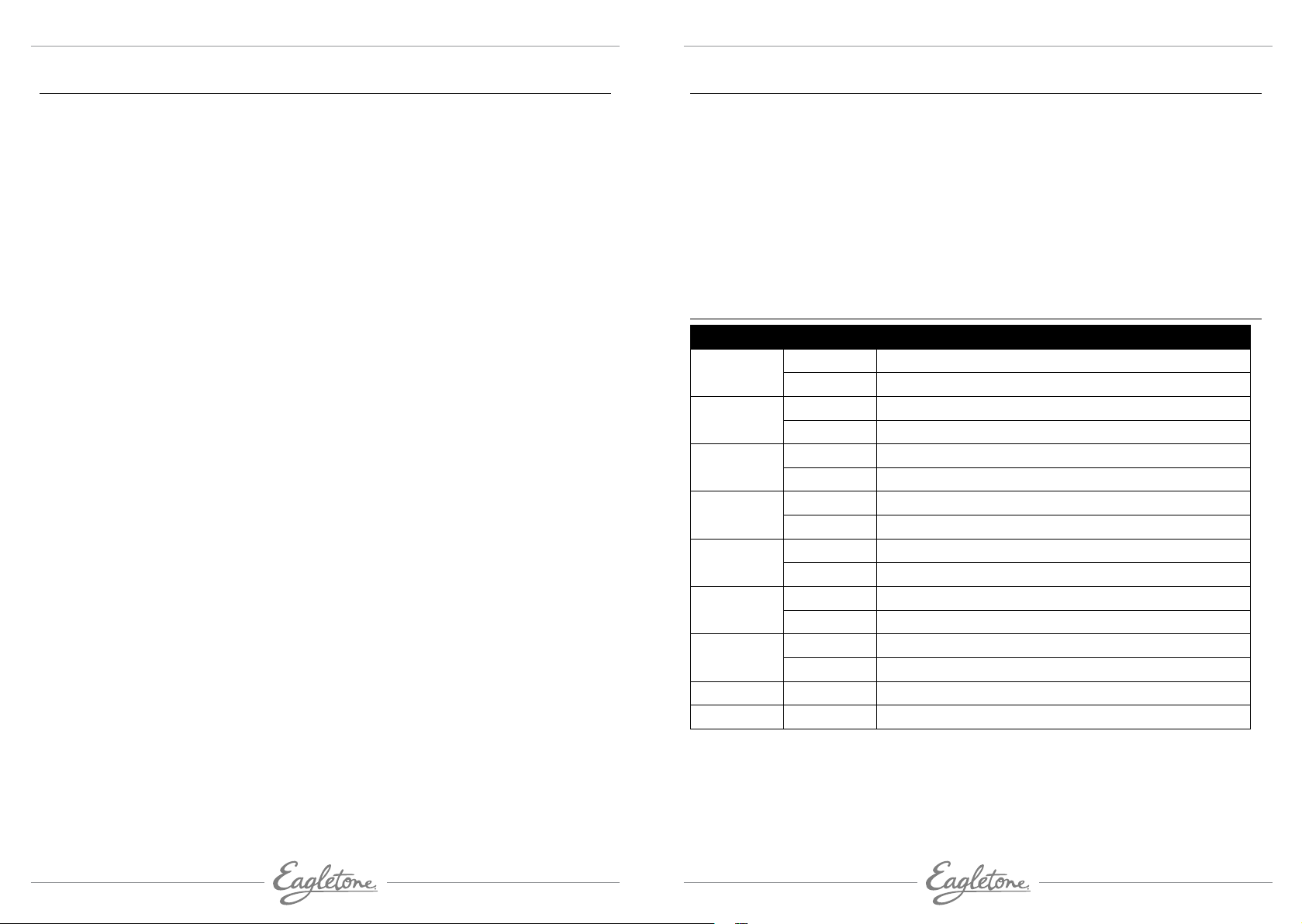
PARAMÉTRAGE DE L’ADRESSAGE DMX
Affichage Paramètre Fonction
A1 1 A1 1 Mode Lumière rouge activé
A1 9 Rotation du moteur de rapide à lente
A2 1 A2 1 Mode Lumière verte activé
A2 9 Rotation du moteur de rapide à lente
A3 1 A3 1 Mode Lumière bleue activé
A3 9 Rotation du moteur de rapide à lente
A4 1 A4 1 Saut R, V, B pour changer les motifs
A4 9 Rotation du moteur de rapide à lente
A5 1 A5 1 Saut R, V, B pour changer les motifs
A5 9 Rotation du moteur de rapide à lente
A6 1 A6 1 Fade-in et Fade-out (transitions)
A6 9 Rotation du moteur de rapide à lente
A7 1 A7 1 Mode stroboscope
A7 9 Rotation du moteur de rapide à lente
So1 So1 Contrôle par le son lumière blanche, rotation du moteur
So2 So2 Contrôle par le son avec changement des couleurs, rotation
du moteur
Fonctions des canaux DMX
XLR mâle XLR femelle
1. Masse
2. Moins
3. Plus
1. Masse
PRÉCAUTIONS DE SÉCURITÉ
• Conservez ce manuel pour toute référence ultérieure. Si vous vendez cet appareil, veillez à
inclure ce manuel.
• Déballez et vérifiez que l’appareil n’a pas été endommagé durant le transport avant
de l’utiliser.
• Avant d’utiliser cet appareil, vérifiez que la tension électrique ainsi que la fréquence
en vigueur dans votre pays est compatible avec celles de l’appareil.
• Cet appareil est conçu pour une utilisation en intérieur et dans des endroits secs.
• L’appareil doit être utilisé dans des locaux ventilés, en respectant une distance minimale
de 50 cm avec toute surface adjacente. Veillez à ce que toutes les aérations ne soient
jamais obstruées.
• Débranchez l’alimentation électrique avant de procéder au remplacement du fusible ou
à toute autre opération d’entretien ou de dépannage.
• Remplacez toujours le fusible par un fusible de valeur et de type correspondants.
• Veillez à ce qu’aucun matériau inflammable ne soit situé à proximité de l’appareil lorsque
vous l’utilisez.
• Utilisez un câble de sécurité lorsque vous fixez cet appareil.
• Dans le cas d’un dysfonctionnement sérieux de l’appareil, cessez toute utilisation
immédiatement.
• N’essayez jamais de réparer cet appareil vous-même. Des réparations entreprises par
des personnes non qualifiées peuvent entraîner des dommages ou un dysfonctionnement.
Veuillez contacter le centre d’assistance technique homologué le plus proche de chez vous
et veillez à toujours utiliser des pièces de rechange de même type.
• Ne touchez aucuns fils durant l’utilisation de cet appareil pour éviter tout risque
d’électrocution.
• Pour prévenir ou réduire le risque de choc électrique, n’exposez pas cet appareil à la pluie
ou l’humidité.
• Si cet appareil n’est pas utilisé pendant une période prolongée, déconnectez-le de la
source d’alimentation électrique.

www.eagletone.com
eagletone.com
Manuel de l’utilisateur EAGLETONE LIL STROB
user’s manual
DMX CHANNEL FUNCTIONS
CH No.Value Description
10-5 Switch
5-255 Strobe from fast to slow
20Red off
1-255 Fade in/out from dark to light
30Green off
1-255 Fade in/out from dark to light
40Blue off
1-255 Fade in/out from dark to light
5
0-5 Motor stop
5-127 Motor is running
128-255 Motor reverse
6
0-5 Start up CH1-CH5
5-250 Built-in program CH1-CH5 off
251-255 Start sound control
TECHNICAL SPECIFICATIONS
• 7 DMX channels RGB LED Crystal Ball effects
• High output LED Lighting effect produces multi-sharp beams
• 4 operational modes: DMX, Master/Slave, Sound activated, Stand-alone
• Can control Red, Green Blue, White & Strobe/Dimmer
• Electronic dimming: 0-100%
• Sound-controlled via built-in microphone
• Built-in programmed lighting show
• 4 Digital LED Display panel
• Power supply: 100V-230V AC, 60/50Hz
• Power consumption: 20W
• Light source: 6pcs (2x 3W Red, 2x3W Green, 2X3W Blue Leds)
• Packing size: L190 x W190 x H200 mm
• Weight: 1kg

eagletone.com eagletone.com
EAGLETONE LIL STROB EAGLETONE LIL STROB User’s manualUser’s manual
INSTALLATION
The DISCO BOWL light effect can be put everywhere, but you must leave a distance of at least
0.5m between the lamp and an object. Keep the light stable.
Connection to a DMX controller: The DMX512 signal must be connected to the INPUT and
OUTPUT sockets of the unit. Keep the cable run as short as possible in order to avoid signal
losses and interference from other units. The cable length should not be longer than 100m.
Use a standard 3-pin XLR lead to connect the unit to a DMX controller. The XLR connector is
wired as follows:
XLR Pin Configuration
Pin 1 = Ground
Pin 2 = Data Complement (negative)
Pin 3 = Data True (positive)
SETTING OF THE DMX ADDRESS
Display Setting Function
A1 1 A1 1 Red light on mode
A1 9 Motor rotation from fast to slow
A2 1 A2 1 Green light on mode
A2 9 Motor rotation from fast to slow
A3 1 A3 1 Blue light on mode
A3 9 Motor rotation from fast to slow
A4 1 A4 1 R, G, B jumping to change patterns
A4 9 Motor rotation from fast to slow
A5 1 A5 1 R, G, B jumping to change patterns
A5 9 Motor rotation from fast to slow
A6 1 A6 1 Fade-in & Fade-out
A6 9 Motor rotation from fast to slow
A7 1 A7 1 Strobe mode
A7 9 Motor rotation from fast to slow
So1 So1 Sound control white colour, motor rotation
So2 So2 Sound control to change colour, motor rotation
SAFETY INSTRUCTIONS
• Please keep this User’s Manual for future reference. If you sell the unit to another user, be
sure that he also receives this instruction booklet.
• Unpack and check the unit carefully that it has not been damaged during transport before
using the unit.
• Before operating, ensure that the voltage and frequency of power supply match the power
requirements of the unit.
• The unit is for indoor use only in a dry location.
• The unit must be installed in a location with adequate ventilation, at least 50cm from
adjacent surfaces. Be sure that no ventilation slots are blocked.
• Disconnect mains power before fuse replacement or servicing.
• Replace fuse only with the same type.
• Make sure there are no inflammable materials close to the unit during operation.
• Use safety cable when fixing this unit.
• In the event of serious operating problem, stop using the unit immediately.
• Never try to repair the unit by yourself. Repair carried out by unskilled people can lead to
damage or malfunction. Please contact the nearest authorized technical assistance center
and always use the same type of spare parts.
• Do not touch any wires during operation as high voltage might be causing electric shock.
• To prevent or reduce the risk of electrical shock or fire, do not expose this unit to rain or any
moisture.
• If this unit will not be used for a long period of time, disconnect if from power supply.
Table of contents
Languages:
Other Eagletone Dj Equipment manuals

Eagletone
Eagletone ParLED 36UV User manual

Eagletone
Eagletone DMX DISCONTROL 192 User manual

Eagletone
Eagletone D DERBY User manual

Eagletone
Eagletone 6 Eyes Flower User manual

Eagletone
Eagletone Multi Derby User manual

Eagletone
Eagletone MH710 4IN1 User manual

Eagletone
Eagletone BIG STROB 1500W User manual

Eagletone
Eagletone FLATLED 56 User manual
Popular Dj Equipment manuals by other brands

Qtx
Qtx TinyMover 150.461UK user manual

LaserLight
LaserLight Mini clock laser light LL350MCL user manual

Blizzard Lighting
Blizzard Lighting COLORSTORM 252 manual

Godox
Godox UL150 instruction manual

thomann
thomann VARYTEC Hero Mirror user manual

ETC
ETC Source Four XT HID Zoom Grid Louver installation instructions