E&I Locked On HI-Z-800-D User manual

E&I Locked On
Broadband Matching Transformers
HIGH RF VOLTAGES MAY BE PRESENT AT THE OUTPUT OF THIS UNIT. All
operating personnel should use extreme caution in handling these voltages and be
thoroughly familiar with this manual.
Do not attempt to operate this unit prior to reading this manual.

January 2013 Rev A
Warranty
Electronics & Innovation Ltd., (hereafter E&I) warrants for the period of three years from
the date of original delivery, each unit to be free of defects in materials and
workmanship. For the period of 36 months E&I will, at its option, repair or replace
defective parts so as to render the unit fully operational such that it performs according
to the original specifications; free of charge to the original purchaser.
Should warranty service be required, the unit must be returned to E&I, freight cost to be
borne by the owner. If, in our opinion, the unit has been damaged by use outside the
limits prescribed in this manual or by accident, then the warranty shall not be honored.
In such a case E&I will provide an estimate for repair, assuming repair is possible and
provide a quote at standard service rates.
Contents
Chapter 1
General Information……………………………………………………………3
Chapter 2
Operation………………………………………………………………………..4
Chapter 3
Technical Information………………………………………………………….7
Chapter 4
Safety……………………………………………………………………………12

January 2013 Rev A
Chapter 1 Introduction
Locked On is a series of broadband matching transformers covering the frequency
spectrum from 500 KHz to 5 MHz. It is rated at 1000 watts of RF power for output
impedances ranging from 6 –800 .
1.2 INSTRUMENTATION IDENTIFICATION
Each unit is identified by a serial number tag on the back panel of the unit. Both the
model number and the serial number should be quoted to identify specific unit.
1.3 SPECIFICATIONS
Physical and electrical specifications are listed in Table 1-1 below
Table 1-1. SPECIFICATIONS
FREQUENCY COVERAGE:
500 KHz to 5 MHz
INPUT IMPEDANCE
50 ohms, Nominal
OUTPUT IMPEDANCE:
HI - Z
50, 100, 200, 400, 800 Ohms
OUTPUT IMPEDANCE:
LO - Z
6, 12, 25, 50, 100, Ohms
MAXIMUM RATINGS
1000 W input signal
POWER REQUIREMENTS:
100 –240 VAC 47-63 Hz. 4 Amps Max
SIZE:
6.2" H x 11.75" W x 15.25" D
15.56 x 29.85 x 38.74 cm.
WEIGHT:
8.5 pounds / 3.86 kg
CONNECTORS:
BNC input / BNC output
OPERATING TEMPERATURE:
0 –30 C

January 2013 Rev A
Chapter 2 Operation
2.1 INTRODUCTION
The Locked On RF variable matching transformers are used to transform the input of 50
ohms to impedance ranging from 6 to 800 ohms over a frequency range of 500 KHz to 5
MHz.
There are several models that have different options. There are low impedance and
high impedance versions. Additionally they may be ordered with a display that indicates
forward and reflected power simultaneously and a further option allows for ‘hot
switching’ or varying the impedance while a signal is applied to the input of the unit.
See below for designators
1. HI-Z-800 –Standard High Impedance Option
a. HI-Z-800-D Option with Display
b. HI-Z-800-H Option capable of Hot Switching
c. HI-Z-800-DH Option with Display and Capable of Hot Switching
2. LO-Z-6 –Standard Low Impedance Option
a. LO-Z-6-D Option with Display
b. LO-Z-6-H Option capable of Hot Switching
c. LO-Z-6-DH Option with Display and Capable of Hot Switching
2.2. Mains Voltage
The unit accommodates AC line voltages from 100 TO 240 VAC 47 –63 Hz
2.3 OPERATION
A line cord is supplied to form a connection between the mains supply and the rear of
the unit. Plug this into the AC input at the rear of the unit and the AC mains outlet.
2.3.1 Proceed as follows:
(i) Ensure there is at least 3” or 7.5 cm clearance at the rear of the unit for air
flow.
(ii) Turn on AC
(iii) Ensure RF input voltage is not excessive
a. 1000 Watts is the maximum that the unit can tolerate without damage.
(iv) Connect the output of to the load.
(v) Select the desired output impedance.

January 2013 Rev A
(vi) Connect the input signal to the BNC input connector.
2.4 Cautions:
(i) Do not apply an input signal unless AC is on
(ii) Do not switch the impedance selector while RF is applied to the input unless you
have an “H” version
(iii)Do not apply more than 1000 watts
Chapter 3 Technical Description
3.1 GENERAL DESCRIPTION
The Locked On series each consist of a single multi-tap transformer:
The HI-Z-800 transformer schematic is shown below:

January 2013 Rev A
Here the T1 and S1 are shown:
The LO-Z operates is the same way:

January 2013 Rev A
Cooling is performed by a DC fan that is connected to the power supply. In the D option
the power supply also supports control board that measures the forward and reflected
RF power and the LCD display. The power supply is connected to line filter that is part
of the AC input block, as shown below.
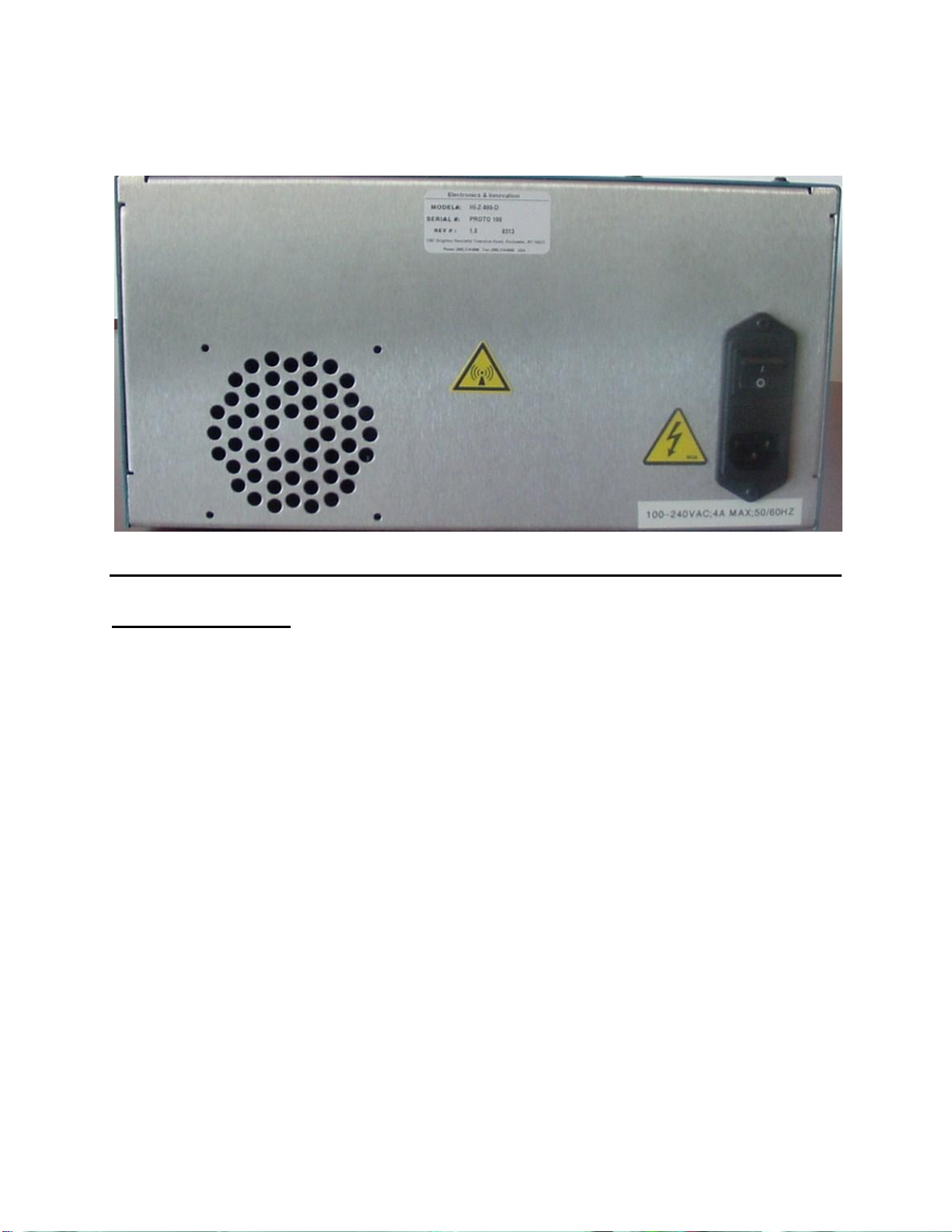
January 2013 Rev A
Shown below is the rear of the unit. There is an air exhaust and the AC input block.
Chapter 4 Safety:
Do not attempt to operate this unit with the cover removed. High AC and DC voltages
are present. The cover protects against electrical shock due to AC line voltages, high
DC and RF fields. Further the cover provides part of the cooling system design.
Components, are prone to over-heat and eventual failure if the unit is operated without
the cover in place.
Ensure that the load is connected to the output prior to connecting the RF input to the
unit. This will prevent high voltages being present and exposed at the output connector.
Only use the AC cord provided or equivalent.
Ensure that the mains outlet is properly grounded.

January 2013 Rev A
Appendix 1
Table of contents
Popular Transformer manuals by other brands

GE
GE OTCF instruction manual

Delta Electronics
Delta Electronics SEL7632V Specification sheet

janitza
janitza CTB Series User Manual and Mounting Instructions

Aqua Quip
Aqua Quip APL 511N Installation & operating instructions

Wolf
Wolf ATEX Operation and maintenance instruction manual

LightPro
LightPro Transformer 24W user manual

Delta Electronics
Delta Electronics Si-Steel Transformers Toridal Series Specification sheet

Daystrom
Daystrom Heathkit IP-22 Assembly manual

Haws
Haws VRKHO7 Installation, operation & maintenance instructions

Fleischmann
Fleischmann 670601 Operating instruction

enphase
enphase CT-100-SPLIT-ROW installation instructions

LEGRAND
LEGRAND LE06499AE Instructions for installation, use and maintenance manual


