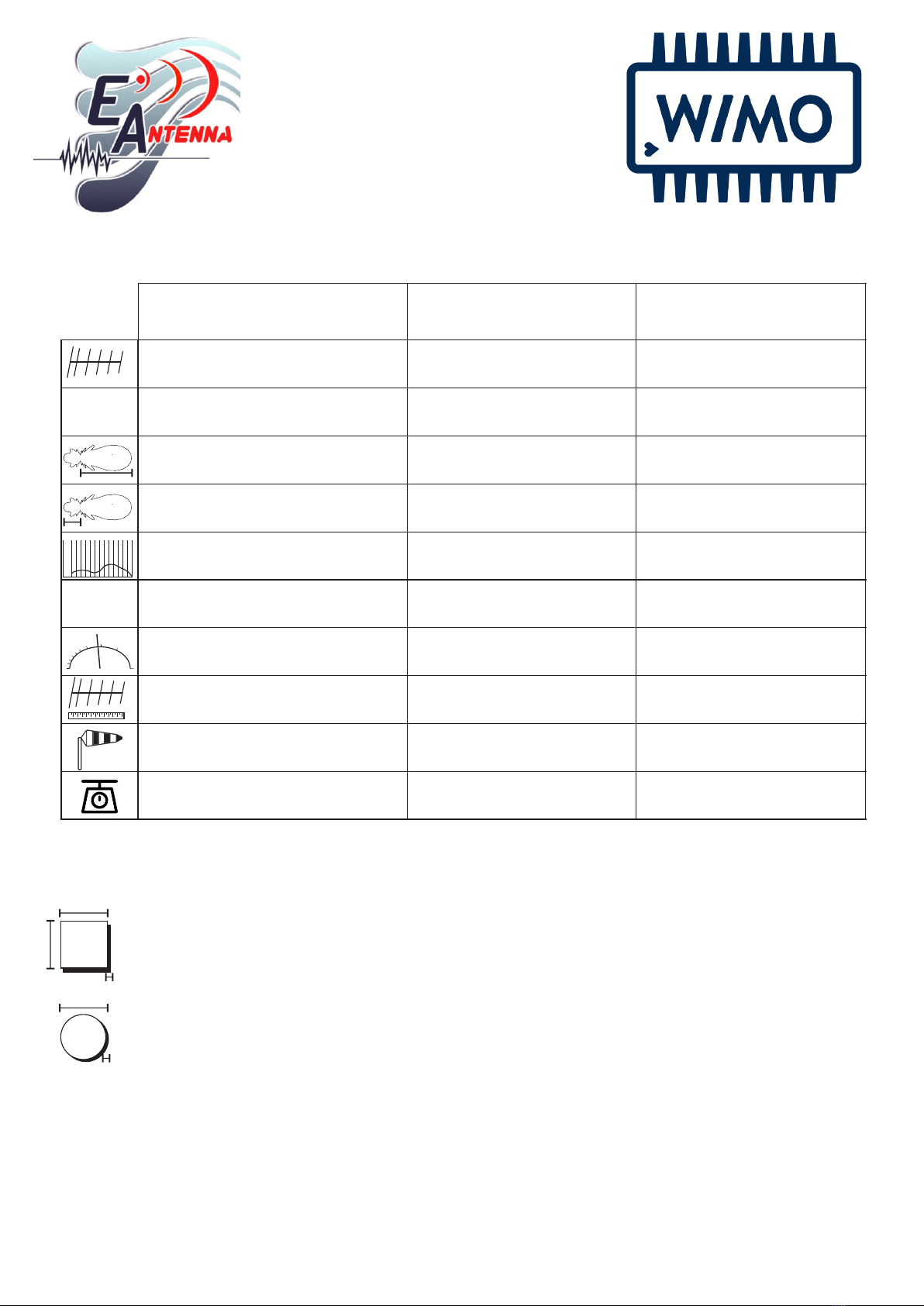
EAntenna 5070OWA8 User manual

5070OWA8
5070OWA8
2,15m
Peso: 4,2 Kg.
Max. Potencia: 5,0 kW
Yagi Antenna
Yagi Antenna
EAntenna's multi-band OWA antennas also represent the biggest development in HF to 70MHz single-band antennas, but optimizing the
results in the same boom several bands.
This performance is characterized by:
The feed is direct to 50 Ohms with a single coax.
The bandwidth of the OWA is the best development of technology to cover the entire bandwidth and have a low SWR.
The radiation lobe is similar to LFA, but has more front gain than LFA.
The F/B ratio is medium to high, compensating for the high frontal gain.
All of this is explained, because in EAntenna: Millimeter by millimeter, we manufacture and build with CNC machinery and/or prepared for
measurements with centimeters, for an exact measurement. Every piece of aluminum is taken care of, filing it of external and internal
surfaces. All this is done by hand, by qualified people prepared for a final product of extreme quality.
All the hardware is stainless Steel W4.
The aluminium used is T5 6061/6063 and T6 6082; the best alloys for manufacturing antennas with extreme weather resistance. Weather
was double here
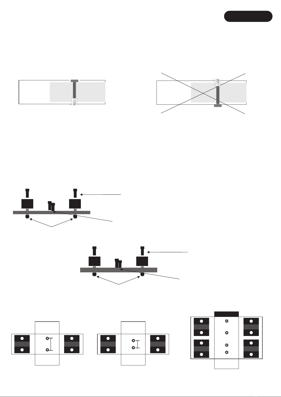
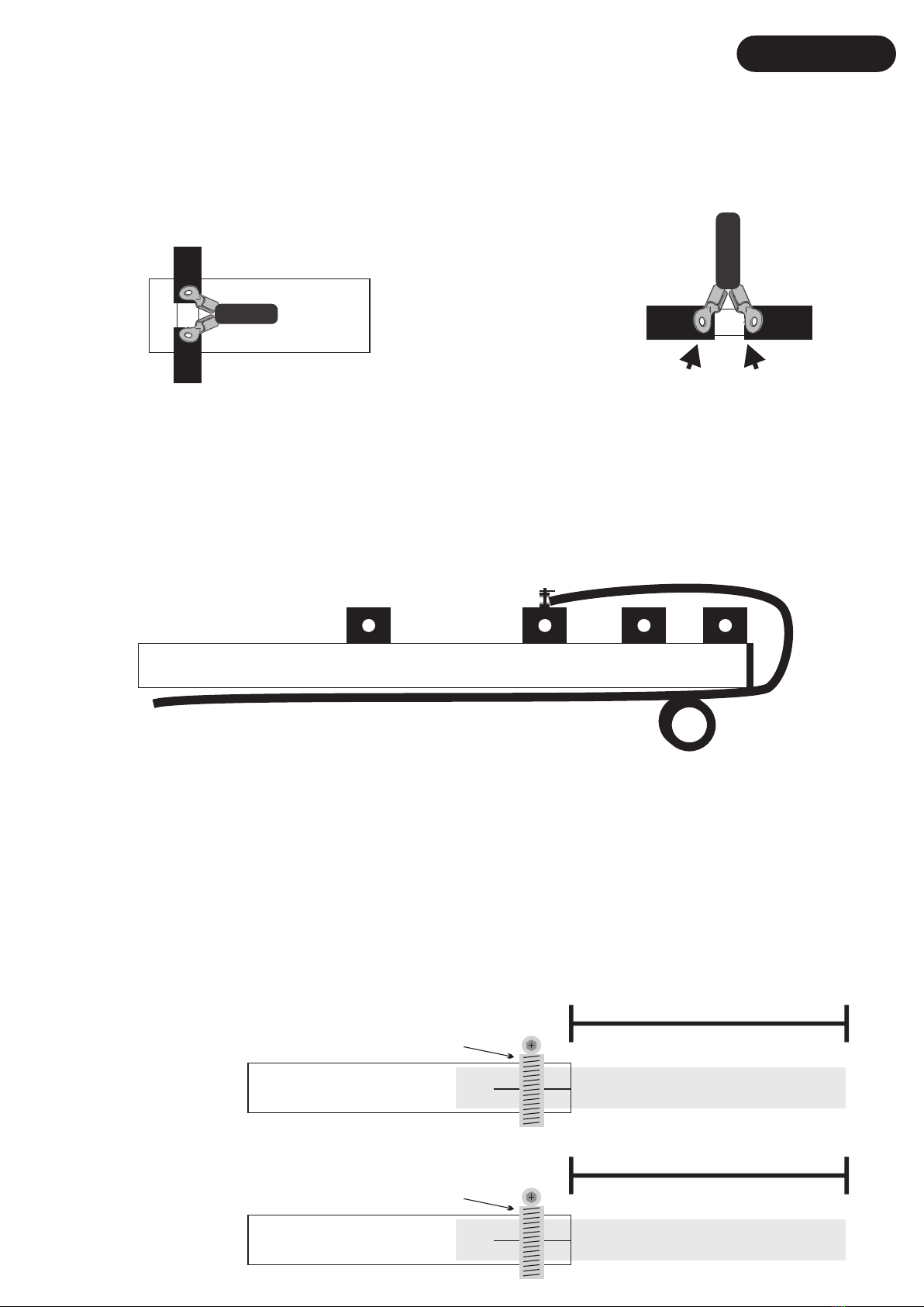
EAntenna's OWA antennas are always insulated from the boom, with German PP (Polypropylene, -30ºC/+60ºC) plastic clamps.
Specifications of the 5070OWA8:
Square boom size is 30x30x2mm.
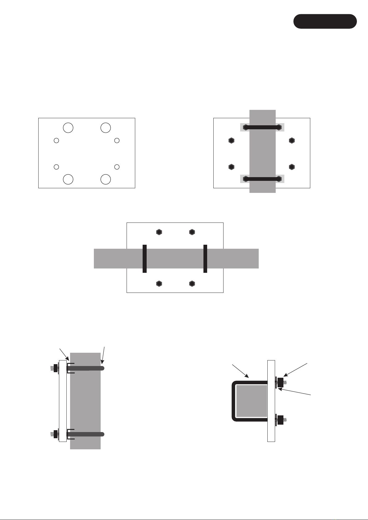
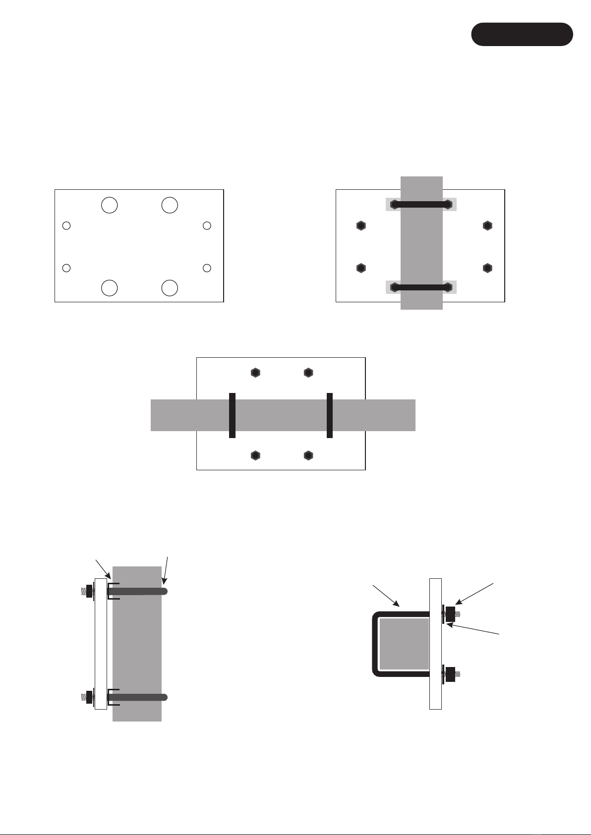
The elements are with 13mm diameter, splitted in 2 parts to get along with a suitable transport length.Mast to plate is an 100x100mm with
6mm thickness and M6 square U-bolts for the boom to the plate and M8 U-bolts for the plate to the mast.
Characteristics of the 5070OWA8
If you can't put 2 antennas on your tower, don't worry, this is your solution to take advantage of the propagation ES seasons on these 2 bands,
You don’t need 2 coax cables, this antenna have only 1 coax to the Radio.
Even when you go to the field or portable, with a simple TV rotor you can move without problems.
Simple and fast assembly, because the pieces of the boom connection are very easy to assemble.
Very solid antenna construction, and with an acceptable weight.
Artikel nr: 17810.64-8
Rev. V1.6 - 22/02/2021

SPECIFICATIONS
EAntenna
5070OWA8
Elements:
4
4
Frequency Range:
50~52 MHz.
70~70,5 MHz.
Gain:
8,6 dBi
8,58 dBi
F/B:
20,43 dB
18,76 dB
SWR:
1,0:1~1,4:1
1,0:1~1,3:1
Impedance
50 Ohms
50 Ohms
Max. Power:
10 kW.
10 kW.
Boom Length:
2,05m
6,72'
Wind Survival
≥ 160kmh / ≥
≥ 100mph
Weight:
5,1 Kg.
11,3 Pounds
14,0.......21,0 MHz.
1
1.3
1.5
2.0
3.0
5.03500 KHz. 3800 KHz.
Ω
300 W.
Boom Size: 30x30x2mm
Element Diameter: 13x1mm

0m
2,916m
0,044m
2,104m
2,13m
0,836m
2,900m
0,935m
1,060m
1,129m
1,200m
2,770m
2,028m
2,054m
1,981m
2,080m
2,660m
2,000m
DRIVEN 6 COAX ELEMENT
DRIVEN 4
REFLECTOR 4
REFLECTOR 6
DIRECTOR 6-1
DIRECTOR 4-1
DIRECTOR 4-2
DIRECTOR 6-2
PLACA/ PLATE

BOOM
BOOM
A A
Para montar el BOOM, tiene que hacer coincidir frontalmente las partes de boom que tienen la misma letra ( p.ej: A-A, B-B, C-C etc), y una
vez hecho, las placas (EA010039) se van fijando con los tornillos DIN 933 M6X16 y arandela DIN 9021 M6. Se recomienda poner todas los
tornillos y arandelas antes de fijarla a tope para no dañar ninguna rosca del BOOM.
(EA010039)
(EA010039)
(EA010039)
(EA010039)
(EA010039)
(EA010039)
DIN 933 M6X16
DIN 9021 M6
ESPAÑOL
BOOM
BOOM
A A
DIN 933 M6X16
DIN 9021 M6
ENGLISH
To mount the BOOM, you have to match frontally boom parts with the same letter (eg: AA, BB, CC etc), and once done, the plates
(EA010039) go with fixing screws DIN 933 M6X16 and washer DIN 9021 M6. It is recommended to put all of the screws with washers in first,
with all in the start with tightening the screws. This avoid damaging the threads in the Boom.

Una vez que tiene los elementos ensamblados, y el boom, es momento de montar los las placas al boom y después los elementos a la placa.
Lo que aconsejamos es que se empiece por el las placas al boom, si montara la antena de una pieza. Si lo que quiere es subir los elemen-
tos, una vez el boom puesto en el mástil, aconsejamos poner los elementos a las placas para su mejor union del conjunto “placa/elemento” al
boom.
Para poner los elementos a la placa, tendría que centrar con la ayuda de una cinta métrica, cada elemento de 13mm Ø, a la mitad (60cm), y una
vez centrado, fijar con la otra parte del (EAHYP013) con los tornillos DIN 912 M6X40, como aparece en el dibujo inferior.
Para colocar cada placa al boom, se fija mediante los tornillos DIN 912 M6X20 y arandela DIN 127 M6. Esta placa debe de quedar bien firme
para la colocación del elemento. El paso siguiente seria igual que los demás elementos, pero teniendo en cuenta que los tornillos que
utilizaremos son DIN 912 M6X40 y tuercas autoblocante DIN 985 M6 una vez que esté ensamblada toda la antena.
S912-9640
DIN 912 6x40mm
S912-9640
DIN 912 6x40mm
4m Plates EA010024
S912-9620
DIN 912 6x20mm + DIN 127 M6
6/4m Plates EA010026
S912-9620
DIN 912 6x20mm + DIN 127 M6
DIN 985 M6
DIN 985 M6
EA010026 EA010024 EA010025
25mm 20mm
PLACA REFLECTORES
ESPAÑOL
El primer paso de ensamblaje de los elementos es colocar en orden por diámetros según la pagina 2.
Una vez hecho esto tener en cuenta que en cada extremo de los elementos hay una parte de cada tubo que tiene los agujeros mar gruesos.
Estos son los que van en el extremo hacia el extremo de la antena, ya que los agujeros anchos son donde entra la cabeza del tornillo DIN 7984
y presiona al tubo interior. Tener en cuenta que la cabeza del tornillo tiene que quedar alojada dentro del hueco del elemento y en la otra
cara, el remache tiene que quedar insertado para atornillarse con la llave allen suministrada.
Mirar ejemplo debajo:
SI NO

To place each plate to the boom, are fixed by screws DIN 912 M6X20 and DIN 127 M6 washer. This plate must be very firm for positioning the
element. The next step would be like the other elements, but considering that the screws use are DIN 912 M6X40 and DIN 985 M6 self-lock
nuts once it is all assembled antenna.
REFLECTOR PLATE
S912-9640
DIN 912 6x40mm
S912-9640
DIN 912 6x40mm
4m Plates EA010024
S912-9620
DIN 912 6x20mm + DIN 9021 M6
DIN 985 M6
DIN 985 M6
6m Plates EA010026
S912-9620
DIN 912 6x20mm + DIN 9021 M6
EA010026 EA010024
25mm 20mm
ENGLISH
YES NO
The first step of assembling the elements is to place in order by diameters according to page 2.
Once this is done keep in mind that at each end of the elements there is a part of each tube that has thick sea holes.
These are the ones that go at the end towards the end of the antenna, since the wide holes are where the head of the DIN 7984 screw enters.
and press the inner tube. Bear in mind that the head of the screw has to be housed inside the hollow of the element and in the other side, the
rivet has to be inserted to be screwed with the Allen key supplied.
See example below:
Measures page 2 are expressed in external lenght , ie, measuring from each end of the tube. Once elements are assembled correctly ,
proceed
to put each item on the plate to the boom , which would be the last step assembly . Attach plates to boom as specified below .
Once you have the elements assembled, and the boom, it's time to mount the plates to the boom and then the elements to the plate.
What we advise is to start with the plates to the boom, if you rise up the antenna in one piece. If what you want is to raise the elements
once the boom is placed on the mast, we recommend putting the elements to the plates for their best way of the “plate / element” assembly to the
boom.
To add the elements to the plate would have to focus with the help of a tape measure, each element of Ø 13mm, mark in the half with a edding,
and a once centered fix to the plate with the green plastic blocks (EAHYP013) with screws DIN 912 M6X40, as shown in the drawing below .
EA010025

PLACAS SUJECIÓN MÁSTIL ESPAÑOL
La placa de sujeción BOOM/MÁSTIL (EA013018) de 200X100X6mm consta de 8 agujeros; 4 gruesos para los abarcones redondos y 4
para los abarcones cuadrados que sujetan el BOOM.
Los 4 agujeros de mayor grosor tienen la función de que hagan la mayor fuerza sobre el mástil, mediante abarcones redondos de M8.
Los abarcones redondos de M8 (A-0163), van fijados mediante arandela DIN 9021 M8 y tuerca DIN 934 M8 proporcionadas en el mismo
abarcón, y fijada al mástil con la Mordaza (23035.50).
Detallamos dibujos para una mayor ilustración:
Vista lateral desde el mástil Vista laterall desde el BOOM
Front view from Mast
Front view from BOOM
(23035.50) (A-0163)
(P0500030) (S934-96)
(S9021-96)
(EA013018) (EA013018)

The clamping plate BOOM / MAST (EA013018) 200X100X6mm consists of 8 holes; 4 thick for round U-bolts and 4 square U-bolts for
securing the BOOM.
The 4 holes are thicker function that make the greatest force on the mast by means of M8 round U-bolts. Round U-bolts M8 (A-0163), are
secured by washer DIN 9021 M8 and nut DIN 934 M8 provided in the same U-bolt, and fixed to the mast with clamp (23035.50).
Detailed drawings for further illustration:
(EA013018) (EA013018)
(23035.50) (A-0163)
(P0500030) (S934-96)
(S9021-96)
MAST TO BOOM PLATE ASSEMBLY
Front view from Mast
Side view from Mast
Front view from BOOM
Side view from BOOM
ENGLISH

Ajuste del ROE/SWR:
Una vez posicionada la antena con sus medidas, quizás necesite algún retoque para conseguir la ROE/SWR deseada.
Desplazando la el elemento DRV.6 hacia adentro o hacia afuera varios milímetros para los 50 MHz. y el DRV4. para los
70 MHz. es la forma de hacerlo.
Buscar que el centro de frecuencia esté en 50,150 y 70,200 MHz., respectivamente. con la menor ROE/SWR. La mejor
opción es ajustarla con analizador de antenas o con la ayuda de un medidor de estacionarias, y estando la antena a 1 o 2
metros del suelo es suficiente para que lo conseguido en el ajuste, nos dé el mismo resultado estando a cualquier otra altura,
ya puesto en la torre/mástil.
Alimentación:
Cuando el montaje está totalmente terminado, lo último es alimentar la antena con el cable coaxial.
Siga los dibujos de como va la alimentación. Simplemente, abrir el coaxial y soldar los 2 terminales suministrados, después
colocando estos en los tonillos del elemento de alimentación (DRV.6) y fijandolo con las tuercas y arandelas.
La posición de los terminales es indiferente. No tiene porque estar el vivo o la malla en un lado u otro del elemento.
ESPAÑOL
13mm Ø
13mm Ø
10mm Ø
10mm Ø
27mm en cada lado
27mm en cada lado
Abrazadera SIN/FIN 8-16mm Ø
(P01000022)
Abrazadera SIN/FIN 8-16mm Ø
(P01000022)
DRV.6
DRV.4
BOOM
COAXIAL
Alimentación Coax
VivoMalla
COAXIAL
Alimentación mediante coaxial:
Después de varios ensayos, vemos que el balun de aluminio hace peor trabajo que un choque de coaxial.
Por esto, recomendamos hacer a escaso centímetros o metros de la alimentación, un choque del coaxial de bajada de 5
vueltas de 8 centímetros de diámetro y así el retorno de RF será mínimo o nulo.
En el dibujo aconsejamos que siempre el choque se haga por debajo de los elementos para que el coaxial no haga intera-
ccion con los elementos.
Boom REF6REF4DRV6
DRV4

ENGLISH
13mm Ø
13mm Ø
10mm Ø
10mm Ø
27mm each side
27mm each side
Hose Clamp 8-16mm Ø
(P01000022)
Hose Clamp 8-16mm Ø
(P01000022)
DRV.6
DRV.4
BOOM
COAXIAL
Feeding Coax
Inner
Braid
COAXIAL
Boom REF6REF4DRV6
DRV4
SWR adjusting:
Once positioned the antenna with your measurements, you may need some fine-tuning to get the SWR desired. Moving the
element DRV.6 inward or outward several millimeters to 50 MHz and DRV4. for 70 MHz is the way to go.
Find the center frequency is at 50,150 and 70,200 MHz, respectively. with the lowest SWR. best option is to adjust with antenna
analyzer or with the help of a Radio + SWR meter and antenna being 1 or 2 meters above the ground is enough , give us the
ame result being any other height, and put in the tower / mast.
Feeding:
When the installation is fully completed, the last step is feed the antenna with coaxial cable. Follow the drawings.
Simply, cut and open the 2 coax and solder terminals supplied after placing these in the Driven element (DRV.6) and fixing
it with nuts and washers. The terminal position is irrelevant. Does not have to be alive or mesh on one side or another element.
Coax cable feeding:
After several trials, we see that the balun aluminum makes it worse job than a coaxial choke. For this, we recommend 5 turns
of 8 cm and thus the RF return will be minimal or absent.
In the drawing advise you to do the clash below the coaxial elements do not causes interaction with the elements.

PACKING LIST
LISTA DE PIEZAS BOLSA 1 - BAG #1
PART #
PIEZA Nº
IMAGEN
PART IMAGE
DESCRIPCION
DESCRIPTION
MEDIDAS
SIZES
CANTIDAD
QUANTITY
BOLSA 2 - BAG #2
Abrazadera Sin-Fin
Hose clamp 4
P0100022
M4x10mm 14
S7984-9410
Remache M4
M4 Insert
DIN 7984
M4
8-12mm
14
RIVSS_M4
PART #
PIEZA Nº
IMAGEN
PART IMAGE
DESCRIPCION
DESCRIPTION
MEDIDAS
SIZES
CANTIDAD
QUANTITY
EA013018
Placa Mástil/Boom
Mast and Boom plate
100 x 100 x 6mm
Abarcon
U-Bolt.
Mordaza
Tube Clamp
Abarcon Cuadrado
Square U-bolt
DIN 9021
DIN 934
50mm
50mm, M8
M6 x 30mm
M6
M6
2
2
4
4
1
2
23035.50
P0500030
A-0163
S9021-96
S934-96
Llave Fija 10mm 1
P1300003
DIN 127 WASHER
DIN 934 NUT
M8
M8 4
4
S127-98
S934-98
Llave Allen 5 5mm 1
P1300001

PART #
PIEZA Nº
IMAGEN
PART IMAGE
DESCRIPCION
DESCRIPTION
MEDIDAS
SIZES
CANTIDAD
QUANTITY
BOLSA 3 - BAG #3
Plásticos 13mm Ø
13mm Ø Plastic Blocks 13mm Ø 16
Tornillo Allen DIN 912
Allen DIN 912 Screw
Tornillo Allen DIN 912
Allen DIN 912 Screw
M6x40mm
M6x20mm
32
16
S912-9640
S912-9620
DIN 127 M6 16
S127-96
Placa para Elementos
Elements plates
Placa para Elementos
Elements plates
150x50x4mm 3
EA010026
Placa para Elementos
Elements plates 150x50x4mm 3
EA010024
DIN 985 M6 32
S985-906
EA010025 150x100x4mm 1
EAHYP013
PART #
PIEZA Nº
IMAGEN
PART IMAGE
DESCRIPCION
DESCRIPTION
MEDIDAS
SIZES
CANTIDAD
QUANTITY
BOLSA 4 - BAG #4
DIN 9021 M6 8
S9021-96
EA0120010
200 x 35mm
Tornillo Allen DIN 933
Allen DIN 933 Screw
Piezas unión de Boom
Boom joint part
M6x16mm 8
2
EA010039
S933-9616
200mm x 10mm 7
.
.
Union de Elementos
Elements joints

PART #
PIEZA Nº
IMAGEN
PART IMAGE
DESCRIPCION
DESCRIPTION
MEDIDAS
SIZES
CANTIDAD
QUANTITY
BOOM A
BOOM B
1395mm x 30mm
740,5mm x 30mm
100mm x 10mm
1458mm x 13mm
1052mm x 13mm
1423mm x 13mm
1000mm x 13mm
1385mm x 13mm
1014mm x 13mm
1000mm x 13mm
1330mm x 13mm
1
1
4
2
2
2
2
2
2
2
2
50OWA8
A
50OWA8
B
PACKING LIST
LISTA DE PIEZAS
.
.
.
.
.
.
.
.
REFLECTOR 6m
REFLECTOR 4m
DRIVEN 6m
DRIVEN 4m
DIRECTOR #1-6m
DIRECTOR #1-4m
DIRECTOR #2-4m
DIRECTOR #2-6m
Punta final de ajuste
Adjustmen tips elements
This manual suits for next models
1
Table of contents
Languages:
Other EAntenna Antenna manuals
Popular Antenna manuals by other brands

Kathrein
Kathrein CAS 120 manual

Ubiquiti
Ubiquiti airMAX Omni AMO-2G10 Anchoring requirements and Instructions

CUSHCRAFT
CUSHCRAFT AV80 Assembly and installation instructions

Ubiquiti
Ubiquiti AirMax Sector quick start guide

Ubiquiti
Ubiquiti AP-5AC-90-HD Air Prism quick start guide

Majestic
Majestic UFO X manual