EAntenna 50LFA5 User manual

50LFA5
50LFA5
Peso: 6,9 Kg.
Max. Potencia: 5,0 kW
yagi antenna
yagi antenna
4,48m
17740.6-5
Rev. V1.5 - 14/01/2021
Thank you for choosing EAntenna.
All our products are manufactured and developed with the best materials on the market, to offer the best qualities and guarantees to our
customers.
The LFA antennas have an input impedance of 50 Ohm in the antenna, so no coupling is necessary. The loop is at the same time a coupling
system and director element and this presents many advantages when modeling.
The 'real' impedance of each LFA varies greatly. But, the impedance presented at the antenna entry point is always 50 Ohm. Therefore, there
is no limitation on the results of any optimization tool achieved with a single input impedance, but it manages to change the width and length of
the loop keeping the impedance at 50 Ohm. This feature is very important to ensure good performance, bandwidth and low SWR in the
antenna.
This additional flexibility also allows more lateral lobes to be suppressed and a better front-to-back (F / B) ratio compared to traditional Yagis.
With time it is possible to achieve an excellent balance between design, F/B, gain and bandwidth.
Additionally, the proximity of the loop and the antenna entry point make the LFA less susceptible to noise and static nearby. In addition, the low
level of the LFA lateral lobes provides a winning formula for an antenna with super low noise!
We detail the materials used, for their best use and assembly. All the fittings are made of stainless steel and the aluminum is made of T6061 or
T6063 alloy, known as Duralumin that offers the best conditions to be weatherproof, the force of the wind and the best conductivity. The
plastics used, are Polyamide and offer the best hardness and durability for years and years.
We offer warranty on operation, and warranty on hardware, delivering the hardware kit with some additional pieces for possible losses or
forced breaks. In addition, we offer Allen keys and fixed mounting elements.
In the following pages you can see detailed graphics of the parts.

SPECIFICATIONS
50LFA5
Elements:
5
Frequency Range:
50,0~51,0 MHz.
Gain:
10,62 dBi
F/B:
24,92 dB
SWR:
1,0:1~1,2:1
Impedance
50 Ohms
Max. Power:
5 kW.
Boom Length:
4,48m
Wind Survival
≥ 200kmh / ≥ 125mph
Weight:
6,9 Kg.
14,0.......21,0 MHz.
1
1.3
1.5
2.0
3.0
5.03500 KHz. 3800 KHz.
Ω
300 W.
Boom Size: 30x30x2mm
Element Diameter: Center Element 13x1mm - Tips: 10x1mm

Not to Scale
Medidas no a escala
REF
0,9195m
D1
0,8195m
D2
0,767m
D3
0,6845m
1,2m
DE1
ALIMENTACION
FEEDPOINT
DE2
+/- 0,648m
+/- 1600mm
Placa Mástil
Mast Plate
0,280m
0,280m
0m
0,573m
0,525m
1,261m
1,785m
0,853m
1,378m
2,639m
4,424m
ESPAÑOLENGLISH

BOOM
BOOM
A A
Para montar el BOOM, tiene que hacer coincidir frontalmente las partes de boom que tienen la misma letra ( p.ej: A-A, B-B, C-C etc), y una
vez hecho, las placas (EA010039) se van fijando con los tornillos DIN 933 M6X16 y arandela DIN 9021 M6. Se recomienda poner todas los
tornillos y arandelas antes de fijarla a tope para no dañar ninguna rosca del BOOM.
(EA010039)
(EA010039)
(EA010039)
DIN 933 M6X16
DIN 9021 M6
ESPAÑOL
BOOM
BOOM
A A
(EA010039)
(EA010039)
(EA010039)
DIN 933 M6X16
DIN 9021 M6
ENGLISH
To mount the BOOM, you have to match frontally boom parts with the same letter (eg: AA, BB, CC etc), and once done, the plates
(EA010039) go with fixing screws DIN 933 M6X16 and washer DIN 9021 M6. It is recommended to put all of the screws with washers in first,
with all in the start with tightening the screws. This avoid damaging the threads in the Boom.

13mm Ø 10mm Ø10mm Ø 6mm Ø
ABRAZADERA 8-12mm Ø
(P01000022)
ABRAZADERA 7-11mm Ø
(P01000031)
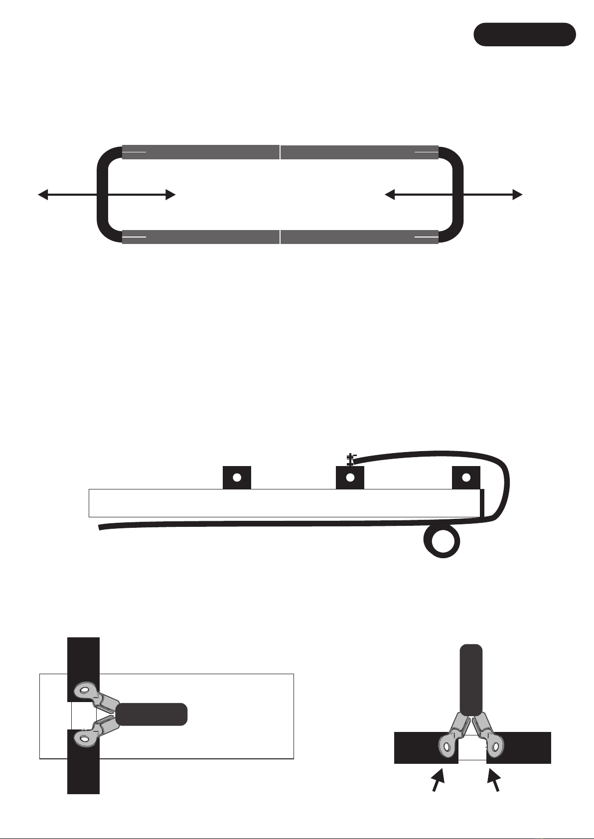
La fijación de los elementos del Rectangulo DE, es mediante abrazadera Sin/Fin 8-12mm (P0100022) de los elementos de 13 a 10mm y la
Sin/Fin 7-11mm (P0100031) de 10 a 6 mm.
Las medidas de la pagina 2 están expresadas en medidas exteriores, o sea, midiendo desde cada extremo del tubo. Una vez que los
elementos estén ensamblados correctamente, se procede a poner cada elemento en la placa al boom, con lo que seria el ultimo paso de
montaje. Unir las placas al boom como se especifica debajo.
Una vez que tiene los elementos ensamblados, y el boom, es momento de montar los las placas al boom y después los elementos a la placa.
Lo que aconsejamos es que se empiece por el las placas al boom, si montara la antena de una pieza. Si lo que quiere es subir los elemen-
tos, una vez el boom puesto en el mástil, aconsejamos poner los elementos a las placas para su mejor unión del conjunto “placa/elemento” al
boom.
Para poner los elementos a la placa, tendría que introducir los EAHYP013 por cada extremo en cada extremo del elemento de 13mm Ø,
y con la ayuda de una cinta métrica marcar a la mitad (60cm), y una vez centrado, fijar con la otra parte del (EAHYP013) con los tornillos DIN 912
M6X40, como aparece en el dibujo inferior.
Para colocar cada placa al boom, se fija mediante los tornillos DIN 912 M6X20 y arandela DIN 9021 M6. Esta placa debe de quedar bien firme
para la colocación del elemento. El paso siguiente seria igual que los demás elementos, pero teniendo en cuenta que los tornillos que
utilizaremos son DIN 912 M6X40 y tuercas autoblocante DIN 985 M6 una vez que esté ensamblada toda la antena.
ESPAÑOL
ELEMENT ALIMENTACIÓN
Placas 6m
DIN 912 6x40mm
DIN 912 6x20mm
DIN 9021 M6
DIN 985 M6
El primer paso de ensamblaje de los elementos es colocar en orden por diámetros según la pagina 2.
Una vez hecho esto tener en cuenta que en cada extremo de los elementos hay una parte de cada tubo que tiene los agujeros mar gruesos.
Estos son los que van en el extremo hacia el extremo de la antena, ya que los agujeros anchos son donde entra la cabeza del tornillo DIN 7984
y presiona al tubo interior. Tener en cuenta que la cabeza del tornillo tiene que quedar alojada dentro del hueco del elemento y en la otra
cara, el remache tiene que quedar insertado para atornillarse con la llave allen suministrada.
Mirar ejemplo debajo:
SI NO

To place each plate to the boom, are fixed by screws DIN 912 M6X20 and DIN 9021 M6 washer. This plate must be very firm for positioning the
element. The next step would be like the other elements, but considering that the screws use are DIN 912 M6X40 and DIN 985 M6
self-locking nuts once it is all assembled antenna.
DRIVEN ELEMENT
ENGLISH
13mm Ø 10mm Ø10mm Ø 6mm Ø
HOSE CLAMP 8-12mm Ø
(P01000022) HOSE CLAMP 7-11mm Ø
(P01000031)
6m Plates
DIN 912 6x40mm
DIN 912 6x20mm
DIN 9021 M6
DIN 985 M6
The first step of assembling the elements is to place in order by diameters according to page 2.
Once this is done keep in mind that at each end of the elements there is a part of each tube that has thick sea holes.
These are the ones that go at the end towards the end of the antenna, since the wide holes are where the head of the DIN 7984 screw enters.
and press the inner tube. Bear in mind that the head of the screw has to be housed inside the hollow of the element and in the other face, the
rivet has to be inserted to be screwed with the Allen key supplied.
See example below:
YES NO
The fixing of the LOOP element, each element is using a Hose Clamp 8-12mm (P0100022) the 13 to 10mm diameter and 7-11mm (P0100031)
to the 10 to 6mm.
Measures page 2 are expressed in external lenght , ie, measuring from each end of the tube. Once elements are assembled correctly ,
proceed
to put each item on the plate to the boom , which would be the last step assembly . Attach plates to boom as specified below .
Once you have the elements assembled, and the boom, it's time to mount the plates to the boom and then the elements to the plate.
What we advise is to start with the plates to the boom, if you rise up the antenna in one piece. If what you want is to raise the elements
once the boom is placed on the mast, we recommend putting the elements to the plates for their best way of the “plate / element” assembly to the
boom.
To add the elements to the plate would have to focus with the help of a tape measure, each element of Ø 13mm, mark in the half with a edding,
and a once centered fix to the plate with the green plastic blocks (EAHYP013) with screws DIN 912 M6X40, as shown in the drawing below .

PLACAS SUJECIÓN MÁSTIL ESPAÑOL
La placa de sujeción BOOM/MÁSTIL (EA013013) de 200X100X6mm consta de 8 agujeros; 4 gruesos para los abarcones redondos y 4
para los abarcones cuadrados que sujetan el BOOM.
Los 4 agujeros de mayor grosor tienen la función de que hagan la mayor fuerza sobre el mástil, mediante abarcones redondos de M8.
Los abarcones redondos de M8 (A-0163), van fijados mediante arandela DIN 9021 M8 y tuerca DIN 934 M8 proporcionadas en el mismo
abarcón, y fijada al mástil con la Mordaza (23035.50).
Detallamos dibujos para una mayor ilustración:
Vista lateral desde el mástil Vista laterall desde el BOOM
Front view from Mast
Front view from BOOM
(23035.50) (A-0163)
(P0500030) (S934-96)
(S9021-96)
(EA013013) (EA013013)

The clamping plate BOOM / MAST (EA013013) 200X100X6mm consists of 8 holes; 4 thick for round U-bolts and 4 square U-bolts for
securing the BOOM.
The 4 holes are thicker function that make the greatest force on the mast by means of M8 round U-bolts. Round U-bolts M8 (A-0163), are
secured by washer DIN 9021 M8 and nut DIN 934 M8 provided in the same U-bolt, and fixed to the mast with clamp (23035.50).
Detailed drawings for further illustration:
MAST TO BOOM PLATE ASSEMBLY
Front view from Mast
Side view from Mast
Front view from BOOM
Side view from BOOM
ENGLISH
(23035.50) (A-0163)
(P0500030) (S934-96)
(S9021-96)
(EA013013) (EA013013)

Ajuste del ROE/SWR:
Una vez posicionada la antena con sus medidas, quizás necesite algún retoque para conseguir la ROE/SWR deseada.
Desplazando la pieza curva hacia adentro o hacia afuera varios milímetros, es la forma de hacerlo. Buscando que el
centro de Frecuencia esté en 50,150 MHz. con la menor ROE/SWR. La mejor opción es ajustarla con analizador de ante-
nas o con la ayuda de un medidor de estacionarias, y estando la antena a 1 o 2 metros del suelo es suficiente para que lo
conseguido en el ajuste, nos dé el mismo resultado estando a cualquier otra altura, ya puesto en la torre/mástil.
ESPAÑOL
Alimentación mediante coaxial:
Después de varios ensayos, vemos que el balun de aluminio hace peor trabajo que un choque de coaxial.
Por esto, recomendamos hacer a escaso centímetros o metros de la alimentación, un choque del coaxial de bajada de 5
vueltas de 8 centímetros de diámetro y así el retorno de RF será mínimo o nulo.
En el dibujo aconsejamos que siempre el choque se haga por debajo de los elementos para que el coaxial no haga intera-
ccion con los elementos.
BOOM
COAXIAL
Vivo
Inner Conductor
Malla
Outter Conductor
COAXIAL
Boom REFDE1
DE2

Adjusting SWR:
Once positioned the antenna with your measurements, you may need some fine-tuning to get the SWR desired. Shifting
the curve piece inward or outward several millimeters, is the way to go. Looking to the center frequency is 50,150 MHz
in the lower SWR. The best option is to adjust with analyzer or with the help of a swr meter and antenna 1 or 2 meters above
the ground while it is sufficient to have achieved in the setting, give us the same results being any other height on the tower or
mast.
ENGLISH
Coax cable feeding:
After several trials, we see that the balun aluminum makes it worse job than a coaxial choke. For this, we recommend 5 turns
of 8 cm and thus the RF return will be minimal or absent.
In the drawing advise you to do the clash below the coaxial elements do not causes interaction with the elements.
BOOM
COAXIAL
Vivo
Inner Conductor
Malla
Outter Conductor
COAXIAL
Boom REFDE1
DE2


Plotter de Elevación ESPAÑOLENGLISH

Plotter de Azimut ESPAÑOLENGLISH

Gráfico de R.O.E. ESPAÑOLENGLISH

PACKING LIST
LISTA DE PIEZAS BOLSA 1 - BAG #1
PART #
PIEZA Nº
IMAGEN
PART IMAGE
DESCRIPCION
DESCRIPTION
MEDIDAS
SIZES
CANTIDAD
QUANTITY
BOLSA 2 - BAG #2
DIN 9021 M6
8-12mm
7-11mm
12
S9021-96
Tornillo Allen DIN 912
Allen DIN 912 Screw M6x20mm 12
S912-9620
Placa para Elementos
Elements plates 150x50x6mm 6
EA010026
Abrazadera Sin-Fin
Hose clamp
Abrazadera Sin-Fin
Hose clamp
4
4
P0100022
P0100031
ESPAÑOLENGLISH
PART #
PIEZA Nº
IMAGEN
PART IMAGE
DESCRIPCION
DESCRIPTION
MEDIDAS
SIZES
CANTIDAD
QUANTITY
EA013013
Placa Mástil/Boom
Mast and Boom plate
200 x 100 x 6mm
Abarcon
U-Bolt.
Mordaza
Tube Clamp
Abarcon Cuadrado
Square U-bolt
DIN 9021
DIN 934
50mm
50mm, M8
30mm
M6
M6
2
2
4
4
1
2
23035.50
P0500030
A-0163
S9021-96
S934-96
Llave Fija 10mm 1
P1300003
DIN 127 WASHER
DIN 934 NUT
M8
M8 4
4
S127-98
S934-98
Llave Allen 5 5mm 1
P1300001

PACKING LIST
LISTA DE PIEZAS ESPAÑOLENGLISH
PACKING LIST
LISTA DE PIEZAS
PART #
PIEZA Nº
IMAGEN
PART IMAGE
DESCRIPCION
DESCRIPTION
MEDIDAS
SIZES
CANTIDAD
QUANTITY
BOLSA 3 - BAG #3
BOLSA 4 - BAG #4
Plásticos
Plastic Blocks 13mm Ø 12
Tornillo Allen DIN 912
Allen DIN 912 Screw
Tornillo Allen DIN 7984
Allen DIN 7984 Screw
M6x40mm 24
S912-9640
Tuerca Autoblocante DIN 985
DIN 985 NUT M6 24
S985-906
ESPAÑOLENGLISH
EAHYP013
M4x10mm 10
S7984-9410
Remache Roscado
Rivnut M4 10
RIVSS_M4
PART #
PIEZA Nº
IMAGEN
PART IMAGE
DESCRIPCION
DESCRIPTION
MEDIDAS
SIZES
CANTIDAD
QUANTITY
DIN 9021 M6 16
S9021-96
Tornillo Allen DIN 933
Allen DIN 933 Screw
Piezas unión de Boom
Boom joint part
M6x16mm
200x35mm
16
4
EA010039
S933-9616

PART #
PIEZA Nº
IMAGEN
PART IMAGE
DESCRIPCION
DESCRIPTION
MEDIDAS
SIZES
CANTIDAD
QUANTITY
BOOM A
BOOM B
BOOM C
1273mm x 30mm
1700mm x 30mm
1505mm x 30mm
573mm x 110mm x 6mm Ø
1
1
1
2
50LFA5
A-A
50LFA5
A-B
50LFA5
B-C
EALOOP57306
PACKING LIST
LISTA DE PIEZAS
.
.
.
.
.
.
.
.
Pieza lateral Loop
Loop Driven
748mm x 10mm Ø
748mm x 10mm Ø
1019,5mm x 10mm Ø
1200mm x 13mm Ø
1200mm x 13mm Ø
1200mm x 13mm Ø
919,5mm x 10mm Ø
867mm x 10mm Ø
784,5mm x 10mm Ø
2
2
2
4
1
1
2
2
2
DE1
DE2
REF
D1
D2
D3
DE1 EXCITADO
DE1 DRIVEN
DE2 EXCITADO
DE2 DRIVEN
REFLECTOR
Parte Central de Elementos
Middle part of Elements
Parte Central de DE1
Middle part of DE1
Parte Central de DE1
Middle part of DE1
DIRECTOR 1
DIRECTOR 2
DIRECTOR 3
. .
ESPAÑOLENGLISH
This manual suits for next models
1
Table of contents
Other EAntenna Antenna manuals
Popular Antenna manuals by other brands

Hirschmann
Hirschmann Hit FESAT 65 operating instructions

Hughes Network Systems
Hughes Network Systems DIRECWAY Assembly instructions

Reflexion
Reflexion CarSat-65MKII TWIN user manual

Triax
Triax BSkyB Assembly & instruction manual

Hirschmann Car Communication
Hirschmann Car Communication AUTA 4000 F 419 L installation instructions

Maxrad
Maxrad MAX-MATICS MIS-GPSPLUS-2 instruction manual