Earth Way 1001-B User manual
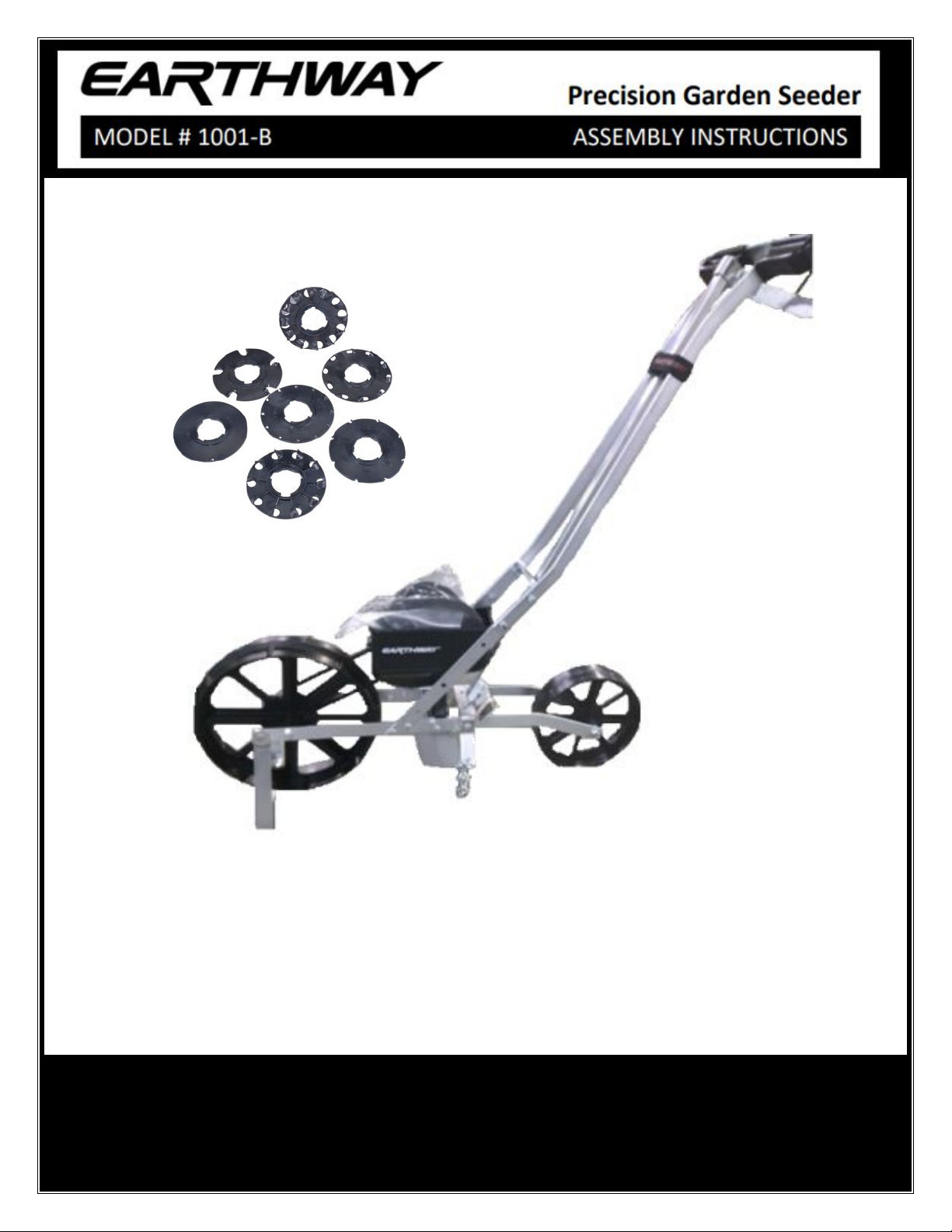
OWNER’S MANUAL
ASSEMBLY INSTRUCTIONS
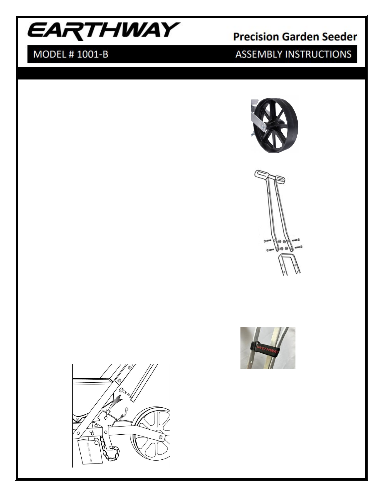
REAR WHEEL
STEP 1: Lower Kick stand at front to hold planter upright.
STEP 2: Remove nut, bolt, and axle from frame.
STEP 3: Insert axle through Rear wheel, then place the
wheel between frame, and line up with holes in end of frame.
STEP 4: Reinstall bolt and nut and tighten.
HANDLE
STEP 1: Remove nuts and bolts from bag. (These are
special lock nuts. A wrench will be required to remove
and install them).
STEP 2: Bolt handle in place using bolt & nut
ROW MARKER
STEP 1: Place row marker shaft in front of row marker bracket
and line up holes
STEP 2: Insert clevis pin through row marker shaft and row
marker bracket and insert hair pin clip through clevis pin. When
not in use, strap the row marker shaft to the handle with the Velcro
strap.
1)Place Velcro behind the row
marker with the Earthway logo to
the right in the upright direction
2)Insert Velcro through the buckle
and pull tight-secure Velcro
together
OPERATING INSTRUCTIONS
To install the desired seed plate, hold the seed plate at an angle with the bottom against the straight wall in the
seed hopper. Line up the slots against the inside of the seed hopper and rotate it approximately ½” in the “ON”
direction as indicated by the arrow on top of the hopper until the cam action locks the seed plate in place on the
hub. Do not force. OFF or ON directions are also indicated on the seed plates.
STEP 1: Prepare seedbed of garden by tilling soil to a depth of 6 or more inches.
STEP 2: To remove a seed plate, hold plate stationary while rotating PULLEY in direction of “OFF” on plate.
push seed plate off white hub by placing your finger through the hole just above the Pulley.
STEP 3: Utilize the SEED PLATE GUIDE to identify the closest spacing and seed size to your chosen seed.
if more distance is desired between seeds, cover every other seed plate hole as required with tape or fill with
bee’s wax.
STEP 4: Pour seeds in the seed hopper. CAUTION: Do not fill the hopper above the center of the seed plate.
NOTE: All the seed, especially small seed, will not be picked up by the plates leaving a small amount in the
hopper. Tilt the seeder to the right as you move down the row to help remove most of the seed if required.
STEP 5: Next set the adjustable planting depth with the wedge-shaped Ground Opener located directly under
the hopper. NOTE: There are graduations in both inches and millimeters on the front angles of the Seed Chute.
Move Ground Opener until top edge is in line with the desired planting depth. Retighten wing nut after
adjustment is made. Check the depth by moving the seeder forward a few inches in soft soil, readjust if
necessary.
STEP 6: Mark out the first row with string and stakes. Lower the Row Marker Shaft and adjust the Row Marker
to the proper width for the next row. Lift the kick stand over the Front Wheel. Be sure the Cover Chain follows
behind the Ground Opener. You are now ready to plant.
STEP 7: To empty any remaining seeds, lower the kick stand and tip the seeder forward until all seeds are
removed. NOTE: When changing seed plates, be sure the seed hopper is completely empty.
NOTICE: KEEP YOUR HOPPER CLEAN AND FREE FROM DUST, SAND, DIRT, AND SEED TREATING MATERIALS.
MAINTENANCE:
You will find one seed plate in place in the hopper, the rest in the box.
1. Any accumulation of dust, dirt, or residue from chemically treated seeds in the seed hopper should be
wiped out with a cloth after each use. A buildup of dirt may cause the seed plate to stick and seeds to pop
out
2. Under certain conditions static electricity may build up on the seed hopper and interfere with planting of
fine seeds. If this situation should occur, wash the seed hopper and seed plate with mild dish washing
detergent, and allow to dry.

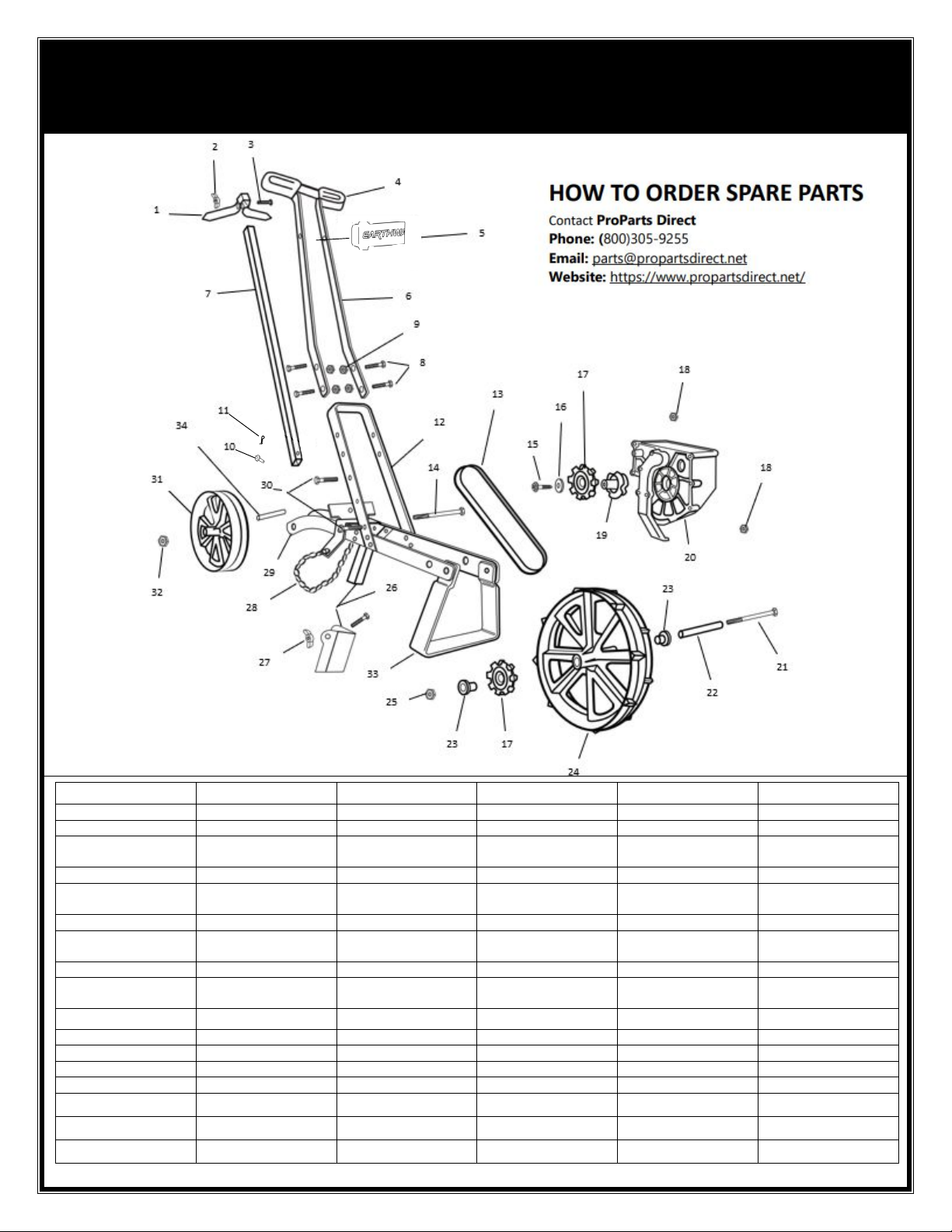
KEY # PART # DESCRIPTION KEY # PART # DESCRIPTION
1 41228 ROW MARKER 18 32100 ¼-20 HEX NUT
2 32107 ^ WING NUT 19 PART OF HOPPER ASSEMBLY
3 37100^ ¼-20X1” CARRIAGE
BOLT
20 60017 HOPPER ASSEMBLY
4 19110 SEEDER GRIP 21 31102 5/16-18X4 1/4
5 70223 VELCRO ADJUSTABLE
STRAP
22 23500# AXLE
6 60011 HANDLE ASSEMBLY 23 12132# BEARING
7 22606^ ROW MARKER SHAFT 24 12102# FRONT WHEEL
ASSEMBLY
8 31101 ¼-20X3/4 BOLT 25 32102 5/16-18
9 32103 ¼-20 LOCKNUT 26 60016 GROUND OPENER AND
SEED CHUTE
10 12133 CLEVIS PIN 27 32107 WING NUT
11 36102 BOW TIE CLIP 28 70104 #6 SING JACK CHAIN
12 41240 UPPER FRAME
29 41241 LOWER FRAME
13 19109 SEEDER BELT 30 31100 ¼-20X1 1/2
14 31102 5/16-18X4 ¼ 31 12101 REAR WHEEL
15 31148* #10 X1 32 32102 5/16-18
16 43024* HUB WASHER 33 41222 KICKSTAND
17
12131
*
PULLEY
34
23500
AXLE
PARTS
^ ROW MARKER ASSEMBLY 60012
*HOPPER ASSEMBLY 60017
#FRONT WHEEL ASSEMBLY 12102
CUSTOMER SERVICE
1009 MAPLE STREET, BRISTOL, IN 46507
574-848-7491
ONE YEAR WARRANTY
EarthWay Products, Inc. warrants this product free of defects in
original workmanship and materials for a period of one year to the end
user with the original purchase receipt. If a manufacturing non-
conformance is found, EarthWay Products, Inc., at its discretion will
repair or replace the part(s)/product at no charge provided the failure is
not the result of incorrect installation, mishandling, misuse, tampering,
or normal wear and tear as determined by EarthWay.
EarthWay at its discretion may require that the part(s) or product be
returned along with the original purchase receipt for examination and
compliance with the terms of this warranty. Do not return any product
without first receiving authorization from EarthWay Products, Inc.
To seek remedy under this warranty, contact EarthWay Products, Inc at
[email protected] or write to EarthWay Products, Inc. 1009
Maple Street, Bristol, IN 46507 and describe the nature of the
manufacturing defect. SPECIFIC LIMITATIONS: This warranty
covers only the part(s) or product; any labor charges associated with
the repair or replacement of non-conformances are specifically
excluded. Due to the corrosive nature of most fertilizers and ice melt
products, Earthway Products, Inc. makes no warranty against and
specifically excludes part(s) or product degradation or failures due to
corrosion or its effects.

OPTIONAL 1600 SIDE-DRESS
FERTILIZER ATTACHMENT
OPTIONAL ACCESSORY: Can be used with row marker in place
ATTACHING:
Slide the 1600 behind the handle and in front of the rear wheel, between the frame and lock
the attaching arms over the rear wheel mounting bolt & nut.
OPERATING INSTRUCTIONS:
Calibrated slide plate allows precise flow rates of all granulated fertilizers. Fertilizer can be
applied on both sides of the planting furrow. Four position positive action ON/OFF handle
helps eliminate waste. Made from durable weather resistant materials for years of dependable
use.
PART #
DESCRIPTION QTY
PART#
DESCRIPTION QTY
31133 #8X ¾ PHPS A 2 12117 HOPPER ASSEMBLY 1
31138 #8X3/8 PMT#8 HD COARSE BLACK 2 36233 ¼-20X1/2 PHPS
4
36223 #6X1/2” TYPE A 2 36308 ¼-20 LOCK NUT W/EXT LW
4
41215 CONTROL ROD 1 60033 HOPPER SUPPORT
1
41216 CONTROL ROD EXTENSION 1 70142 NUT PROTECTOR
1
12123
CONTROL ROD CONNECTOR
1
Table of contents
Other Earth Way Seeder manuals


