manuals.online logo
Brands
  1. Home
  2. •
  3. Brands
  4. •
  5. Earthworks
  6. •
  7. Drum
  8. •
  9. Earthworks DrumKit DK7 User manual

Earthworks DrumKit DK7 User manual

User’s Guide
DK7
DrumKit™
Congratulations on your purchase of the Earthworks DK7 DrumKit™ High Deni-
tion Multi-microphone Drum System. You will be thrilled with the results you will
obtain when using the included microphones. You will hear more detail in the attack
in addition to hearing subtle low level details that are not audible using conventional
microphones. You will now walk into a whole new world of pristine drum sound us-
ing Earthworks High Denition Drum Microphones™. After reading this manual, if
you have any unanswered questions, please email or phone us using the contact
information on the back page of this manual.
Happy Drumming!
Please verify that you have received everything listed below.
Included with the DK7 DrumKit™ Drum Microphone System:
2 – SR25 Cardioid Microphones (overheads)
4 – DM20 DrumMic™ (tom & snare)
1 – SR20LS (kickdrum)
4 – RM1 RimMount™ (for DM20s)
3 – SRW3 Foam Windscreens (for SR25s & SR20LS)
4 – PW1 Windscreens (for DM20s)
1 – High Impact Carrying Case
with custom foam insert
1 – User’s Manual
Version 1, August 15, 2017 1
IMPORTANT NOTICE - Please Read This:
Drums and Microphone Output Level
The SR25, DM20 & SR20LS have been designed for drum applications, and in
most cases will not require the use of a pad to prevent overloading outboard
microphone preamps, preamps in mixers or consoles and computer audio in-
terfaces. The majority of preamps will accommodate high input levels at the
microphone preamp input without distortion. However, some preamps will not
handle high input levels at the preamp input and will require using a pad to pre-
vent distorting. We encourage you to check the specications of your preamps
to verify that they will accommodate high microphone output levels of approxi-
mately +20dBV.
Different Types of Preamp Input Pads
Some outboard microphone preamps, preamps in mixers or consoles and com-
puter audio interfaces may have a built-in pad that can be switched in or out.
However, on some units these pads are not attenuators that precede the pre-
amplier input, but instead just reduce the gain of the preamplier. Unless these
preamplier inputs will handle a high input level (i.e. +20dBV) these so-called
pads will typically provide no preamp input overload protection from high level
microphone signals (see Fig. 1-A). In contrast, other outboard preamps, mixers,
consoles or computer audio interfaces have actual attenuators (pads) that pre-
cede the preamplier input. These types of pads will provide the input overload
protection that is needed (see Fig. 1-B). Such pads will typically provide 10dB or
20dB attenuation. If an external XLR type microphone pad is needed, Earthworks
offers a LevelPad™ that provides 20dB of attenuation and is simply plugged into
the microphone cable. The DM20 and SR20LS have been designed with a lower
output level than the SR25 and should not require an external pad even when
close-miking toms, snares or kickdrums. Likewise, in most cases the SR25 over-
head mics should require no external mic pad. In case you do need an external
mic pad, please read further.
2
Figure 1-A and 1-B Types of Preamp Input Pads
A B
If it becomes necessary to lower the microphone output level to avoid over-
loading the preamp, then the use of an XLR-type outboard pad is suggested.
The Earthworks® LevelPad™ XLR-type outboard mic pad provides 20dB of
attenuation and can be simply plugged into the microphone cable. The Level-
Pad™can be inserted into the microphone cable in one of the three ways
indicated below:
3
Figure 2-A LevelPad™ inserted at the microphone
Figure 2-B LevelPad™ inserted in the microphone cable
Figure 2-C LevelPad™ inserted into mixer mic input
CAUTION: Plugging the LevelPad™ into the mic in-
put of a mixer can cause damage to the mixer input
connector if the LevelPad™ receives a hard push
to the side. However, if you are careful, placing the
LevelPad™ at the mixer mic input can provide greater
accessibility in installing or removing the LevelPad™.
Earthworks Drum Mics
The Earthworks DrumKit™ High Denition Three-Microphone Systems™ have
had great success because they pick up drum sounds with far more detail and
accuracy than conventional microphones. This improved sound quality is due to
proprietary technologies utilized in Earthworks High Denition Microphones™.
Many drummers such as Jeff Campitelli, Steve Gadd, Keith Carlock, Ronnie
Vannucci, Anton Fig and Anthony King, in addition to many FOH engineers
touring with major artists who are using Earthworks High Denition Drum Mi-
crophones™ for overheads, toms, snare and kickdrum with exceptional results.
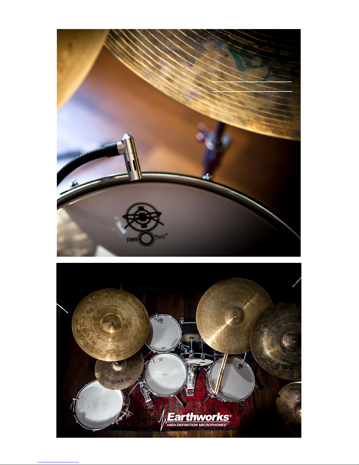
The SR25 has been a popular drum microphone for many years and will han-
dle up to 145dB SPL. The DM20 is a new generation of Earthworks tom and
snare microphones. It features a stable gooseneck for easy positioning that
will stay in place even when the drums are played very hard. It also can handle
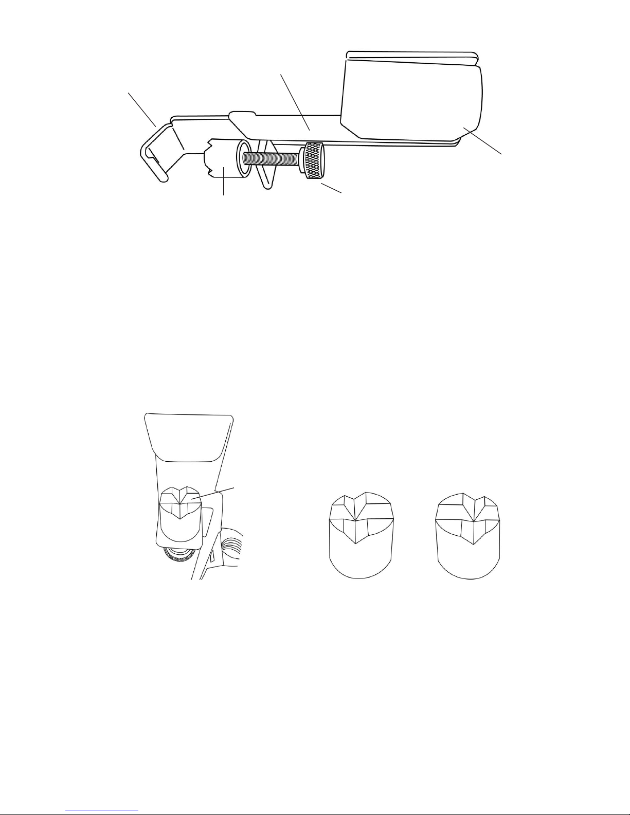
high acoustic sound levels up to 150dB SPL. The Earthworks proprietary
polar technology provides a stunning 32dB of rear rejection (nearly double
that of conventional microphones) and a consistent frequency response out
to 80 degrees off-axis. This vastly reduces phase cancellations, minimizes
pickup of unwanted sounds at the rear of the microphone and provides a sub-
stantial reduction in unwanted acoustic feedback for live sound applications.
Earthworks High Definition Microphones™
the New Science in Microphones
David Blackmer, the brilliant engineer who invented the innovative technol-
ogies of dbx, is also the inventor and founder of Earthworks. In the last few
years of his life, David developed a number of revolutionary technologies that
dramatically improve the sound quality and performance of microphones. In
short, Earthworks High Definition Microphones™ pick up sounds more accu-
rately and with more detail than conventional microphones. These dramatic
improvements are in the areas of impulse response, diaphragm settling time
and advanced polar technologies. Those who have heard Earthworks High
Definition Microphones™ say they have more rear rejection and more gain
before feedback in addition to hearing more detail of the attack, more subtle
detail in low level signals thereby providing a more pristine sound quality than
with any conventional microphones can provide, regardless of price.
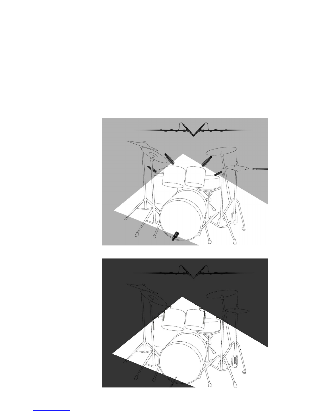
Miking Drums
There are many ways to mic drums and it seems that most every recording or live
sound engineer has their own way of doing this. Our objective is not to indicate
which drum miking approach is better, but to make suggestions and look at ad-
4
5
vantages and disadvantages of each. Every engineer or producer uses their own
methods to obtain the results they desire, and that’s what matters.
Multi-microphone Method
The objective in multi-microphone drum miking is to place a separate micro-
phone on most or all the elements of a drum set. Typically, separate mics are
used on snare, toms, hi-hat and kickdrum, along with one or two overhead
microphones. The overhead mics pick up the overall sound of the drum set
including cymbals (which are typically not miked separately). By this method,
the mixing engineer can control the level, and signal processing (limiting, EQ,
etc.) for each element of the drum set (toms, snare, hi-hat, etc.). This provides
a great deal of control over the sound of the entire drum set and allows bring-
ing out certain patterns on hi-hat, snare, etc. Multi-miked drums are desirable
for live sound, providing more control and increased gain before feedback,
and when recording in a large room with high ambient sound this reduces the
amount of unwanted room sound and provide greater control of the drum mix.
Earthworks Near-Perfect Polar Response
One of Earthwork’s proprietary technologies is near-perfect polar response
i.e. very uniform response over the front 160 degrees of the microphone. Con-
ventional microphones (even expensive ones) have a loss of high frequencies
at the sides of the microphone. Have you ever tried to put three singers on a
single directional microphone? The singer at the front of the mic sounds great,
but the two on the sides of the microphone sound muffled due to the lack of
high frequency pickup at the sides of the microphone. In contrast, the Earth-
works proprietary polar technology provides virtually the same frequency re-
sponse on the sides of the microphone as at the front. This uniform frequency
response at the front and sides of the microphone dramatically reduces phasing
issues. Refer to Figure 3-A & 3-B to see the uniform Earthworks microphone
(A) polar response, in comparison to the conventional microphone (B).
Earthworks SR30 Cardioid
500
1K
2K
4K
8K
15K
Competitive Cardioid
500
2K
15K
10K
1K
20K
5K
500
1K
2K
4K
8K
15
BWithin 12dB
500Hz to
15kHz &
Within18dB
to 20kHz
DM20 Polar Conventional Polar
Figure 3-A & 3-B Earthworks vs. Conventional Polar Response
AWithin 3dB
500Hz to
16kHz
Nearly Twice the Amount of Rear Rejection
One of the typical disadvantages in the multi-microphone approach is picking
up the unwanted sound of other elements of the drum set from the rear of
each microphone. Conventional microphones provide only 18dB of rear rejec-
tion, while Earthworks microphones with 32dB of rear rejection provide nearly
twice the amount of rejection of conventional microphones. The Earthworks
drum mics will nearly eliminate any leakage present at the rear of the mi-
crophone. Figure 4 shows conventional drum microphones with 18dB of rear
rejection and Figure 5 shows the Earthworks drum microphones with 32dB of
rear rejection.
6
Conventional
Microphones
Approx 18dB
Rear Rejection
Figure 4
18dB of
Rear
Rejection
Using
Conventional
Drum mics
Figure 5
32dB of
Rear
Rejection
Using
Earthworks
Drum mics
Earthworks
Microphones
Approx 32dB
Rear Rejection
7
Close Miking Toms and Snares with the
DM20 DrumMic™ Microphones
Inserting the DM20 Microphone into the RM1 RimMount
The RM1 is designed specifically for the DM20 allowing you to mount the mi-
crophone on the side of a tom or snare. The RM1 can also be used on the top
or bottom of a tom or snare.
It is suggested that you insert the DM20 microphone into the RM1 RimMount™
prior to attaching the RimMount™ to the drum.
To insert the DM20 microphone into the RM1 just insert the mic head and the
gooseneck into the rubber holder from the bottom of the RimMount™. Push on
the body of the microphone from the bottom (XLR connector end) to move the
microphone up inside the rubber holder. The fit will be firm, so you will need to
apply a little pressure to move the microphone body up into the rubber holder.
The suggested procedure is shown in Figure 6.
Figure 6 Inserting the DM20 DrumMic™ into the RimMount™
1 2 3 4
Mounting the RM1 RimMount™ to the Drum
The RM1 RimMount™ is designed for metal drum rims, and will not work on
wooden drum rims. Attaching the RimMount to the drum rim is quite easy.
While reading this section, please refer to Figure 7-A, which shows the var-
ious elements of the RimMount™. First, loosen the thumbscrew so there is
more than enough space for the Delrin® cushioned rim-guide to clear the
bottom of the drum rim. Then determine where on the drum rim you want to
position the microphone and place the “hook portion” of the RimMount bracket
over the desired place on the drum rim.
8
Soft Polyolen® Coated
Metal Bracket
Rubber
Holder
Delrin®
Cushioned Rim-guide
Hook Portion
of Bracket
Thumbscrew
Figure 7-A. Elements of the RM1 RimMount™
Referring to Figure 7-B, notice that on the Delrin® cushioned rim-guide there
are two sets of grooves. One groove is in the “center” of the rim-guide (1),
while the other groove (2 & 3) is “off center” (or closer to the edge of the rim-
guide). These two sets of grooves provide you with “three” mounting options:
(A) using the “off center” rim-guide groove will place it closest to the drum
shell, (B) or rotating the “off center” groove 180 degrees will place the rim-
guide furthest away from the drum shell, and (C) the “center” groove will allow
placement in-between the positions (A) and (B).
Figure 7-B Positioning the Cushioned Rim-guide
Centered
Groove
1
Offset Groove
Positioned
on Left
Offset Groove
Positioned
on Right
23
Various types of metal drum rims have the bottom flange of the rim either
closer or further from the drum shell. One of the three positions (A, B or C
previously mentioned) will allow the RimMount™ bracket to be mounted par-
allel to the drum shell. Position the rim-guide so the bottom edge “flange” of
the drum rim fits comfortably into one of the RM-1 rim-guide grooves. This will
ensure that the cushioned rim-guide remains securely in place as you tighten
the thumbscrew to firmly secure the RM-1 to the drum rim. The soft protective
Polyolefin® coating on the RimMount™ bracket will prevent the possibility of
scratching the drum shell finish.
9
Adjusting the Microphone Height
Once the RimMount™ is mounted securely on the drum rim with the DM20
microphone housed in the rubber holder, the microphone body can be moved
either up or down in the rubber holder to provide the desired height. Then
the gooseneck will provide a good amount of latitude in positioning the mi-
crophone head from any microphone body height. Adjusting the height of the
DM20 microphone body is indicated in Figure 8-A and 8-B.
Figure 8-A and 8-B
Adjusting the DM20
Microphone Height
AB
Positioning the Microphone Head
Once the DM20 microphone height has been set, you can position the micro-
phone head. It is suggested that the microphone head be positioned between 1.5
inches and 3 inches above the drumhead. The flexible gooseneck will allow you
to move the microphone head either up or down above the drumhead as well
as in and out from the drum rim. You can also change the angle of the micro-
phone head as shown in Figure 9-A. Figure 9-B shows how the microphone
head can be aimed more toward the center of the drum head by changing the
position of the gooseneck. Keep in mind that the microphone head should
never be placed “parallel” to the drumhead, but should always be at “an angle”
to the drumhead. This will prevent the microphone diaphragm being forced to
its backplate which could cause an unwanted pop or thump in the live sound
or recording system.
Figure 9-A & 9-B
Positioning the
Microphone Head
AB
10
The High Acoustic Sound Levels of Close Miked Drums
In close miking drums, one should keep in mind that the acoustic sound level
at the microphone head is extremely high. Microphones used for close miking
drums should be able to handle at least 140dB SPL in order to prevent audible
distortion. The DM20 DrumMic™ handles up to 150dB SPL. With these high
sound pressure levels, the DM20 microphone output level may be as much as
+15dBV which can overload some types of microphone preamplifier inputs. In-
serting the Earthworks XLR type LP20 LevelPad™ into the microphone cable
will provide 20dB of attenuation to help prevent any distortion or overload. For
full information refer to pages 1 and 2 of this manual.
Close Miking Snare Drums with the DM20
The DM20 has been optimized for miking toms and snare. With its frequency
response of 50Hz to 20kHz, it will provide a full and fat sound from your toms
and a nice crisp sound from your snare. If you feel that there is still too much low
frequency response when miking a snare, use either a high-pass lter set some-
where between 60Hz and 100Hz or a low frequency equalizer (EQ) to attenuate
(i.e. cut) a few dB in the area of 60Hz to 100Hz for the desired results. The DM20
can be used on either the top drumhead, bottom drumhead or both. Figure 10-A
shows the DM20 placed over the top drumhead of a snare, while Figure 10-B
shows a snare drum with both the top and bottom heads miked.
Figure 10-A and 10-B Miking the Top or Top & Bottom of a Snare
AB
Close Miking Toms with the DM20
The extended low frequency response of the DM20 DrumMic™ will provide a rich
and full tom sound. You can mike either the top or bottom head of a tom with the
DM20 as indicated in Figure 11A or B, or you can mike both the bottom and top
drum heads in a similar fashion as shown on a snare in Figure 10-B.
You will notice in Figure 11-A the microphone head is placed closer to the drum
rim, while in Figure 11-B the microphone head is aimed toward the center of the
drumhead by changing the position of the gooseneck. Experiment with the mi-
crophone head placement as the sound or tone can change with various place-
ments.
Earthworks High Denition Microphones™ are widely used successfully by drum-
mers with major artists in both recording sessions and for live performance. The
DM20 is designed to withstand the rigors of the road and will provide you with
many years of exceptional and reliable results. We know that when you use the
Earthworks DM20 DrumMics™ for your recording and live performances you will
be thrilled with the results.
11
Figure 11-A and 11-B Miking the Top Head of a Tom
AB
Drum Overhead Microphone Placement
For overhead drum miking use the SR25s. The low frequency response of the
SR25 will pick up less of the kickdrum and the lower frequencies from the toms.
This will be a help during mixing and provide more control in the mix from the
individual tom and kickdrum mics, rather than having too much low frequency in-
formation in the overhead mics.
X/Y Stereo Overhead Miking
There are two basic ways to position overhead drum mics, either by putting the
mics in an X/Y position or by separating the microphones by some pre-determined
distance. The X/Y position will provide less of a stereo image than the separated
microphone method.
12
AB
Figure 12-A Figure 12-B
Horizontal X/Y Positioning Vertical X/Y Positioning
Figures 12-A and 12-B show two variations of X/Y microphone placement. For
microphone “height” we suggest that you start with the microphone approxi-
mately 2 feet above the drummer’s head. Moving them down will provide more
detail, while moving them higher will capture a wider overall image along with
more room sound. Both the horizontal and vertical X/Y positioning will provide
excellent results in a drum booth or an acoustically treated small room as well
as a large room. If you are using a drum booth or a room with a low ceiling, the
horizontal X/Y version shown in Figure 12-A may be more ideal, as it requires
less height.
Separated Overhead Miking
Another overhead miking approach is called “Separated Overhead Miking.” In
this approach, the microphones are farther apart from each other and can be
positioned closer to the drum set if desired. Placing the overhead mics closer
to certain elements of the drum set can reduce the ambient room sound while
picking up more subtle details of the drums. When using Earthworks High De-
nition Microphones as overheads, you can bring the microphones down closer
to the drums without fear of hearing cymbal splash or splatter.
13
Miking the Hi-Hat
There are many various approaches to miking a hi-hat. We suggest that you use
an SR25 or DM20 and place it approximately two inches above the top hi-hat
cymbal (see Fig 14-A). You can also place the microphone under the hi-hat in
relatively the same position as shown in Figure 14-B. However, if the microphone
is placed close to where the two cymbals come together, bursts of air from the two
cymbals coming together may result in an undesirable thumping or popping sound
(see Fig 14-C).
We also suggest that you place the microphone approximately 2 to 3 inches from
the edge of the hi-hat cymbals (see Fig 15).
A
Overhead miking
front view
B
Overhead miking
aiming positions
top view
Figure 13-A and 13-B Separated Overhead Miking
A
B
C
Figure 14-A, B & C Miking a Hi-hat (front view)
14
Miking a Kickdrum with a Hole in the Front Head
If there is a hole in the front head of the kickdrum, do not place the mic directly
in front, or slightly inside of the hole as there will be a large burst of air hitting
the microphone. The velocity of the air is dramatically reduced when placing the
microphone head inside the kickdrum (several inches inside). This will still allow
Figure 15 Miking a Hi-hat (top view)
Using the SR20LS on Kickdrum with No Hole in the Front Head
The Earthworks SR20LS microphone is supplied for miking kickdrums and is a
precision condenser microphone which is sensitive to large bursts of air. Howev-
er, this microphone, when positioned properly, will produce an incredible kickdrum
sound. For optimum results it is crucial to place the SR20LS at a 45 degree angle
to the head (which reduces the air burst at the front of the microphone). Whether
your kickdrum has a front head or not, place the SR20LS at a 45 degree angle to the
front of the drum head as indicated in Figure 16-B and 16-C. Do not place the front
of the microphone parallel with the drum head as shown in Figure 16-A.
In our eld tests, we achieved the best results and the best sound by miking the
drum just off of the rim as shown in Figure 16-B, or you can mic the center of the
kickdrum as shown in gure 16-C. Whatever your approach, if you get any pop-
ping from the air bursts, place the enclosed windscreen on the kickdrum mic, and
place the mic at a 45 degree angle to the drum head.
A B C
DO NOT MIKE
LIKE THIS!
Figure 16-A, 16-B and 16-C Miking a Kickdrum
15
Using the KickPad™
The KickPad is a passive signal processor that requires no phantom power and
will not interfere with the phantom power for your microphone. It can be inserted
directly into the XLR connector on the microphone, or somewhere in the mic cable
you to get the nice fat bottom end in addition to hearing more of the snap of the
beater from the rear head. We suggest that you experiment with placement of the
SR20LS using the suggested guidelines in Figures 17 to obtain the best results.
Again, the highest velocity air from the hole is close to the hole at the front head,
or slightly inside the hole. Figure 17-A, 17-B & 17-C show where not to place the
kickdrum microphone. Figure 17-D & E show our suggestions for best results in
placing the SR20LS inside the hole on the front drum head. With the microphone
inside the drum (Figure 17-D) it should not matter whether the microphone is
parallel or at an angle to the beater head. If you do get some pops, then place the
enclosed foam windscreen on the kickdrum mic.
Figure 17-A, Incorrect
Placement of SR20LS at
Hole in Front Drum Head
A
Figure 17-B & C Incorrect Placement of SR20LS at Hole in Front Drum Head
B C
Figure 17 D & E “Correct Placement” of SR20LS at Hole in Front Drum Head
A - mic tip approx 6” inside and B - mic tip approx half-way inside kickdrum
DE
16
between the microphone and the mixer input, or, it can be plugged directly into the
microphone input of the mixer.
A good kickdrum microphone must be designed and optimized for that specic
purpose, which means that particular microphone would be great for kickdrum
and little else. Instead, we designed our kickdrum optimization in an external
XLR package - the KickPad™. Just plug the KickPad™ into the mic cable going
to the SR20LS kickdrum mic for magnicent results. It will instantly make the low
frequencies of the kickdrum sound louder and fatter and add more snap or click to
the beater sound. Keep in mind that this is also a pad and will reduce the output
level from the kickdrum mic, so you may need to increase the gain on the mic pre-
amp. The results from the KickPad™ may vary due to the combined impedances
of your microphone and preamp. This is more pronounced when using preamps
with transformer inputs with an input impedance of 1000Ω or lower.
As an added bonus, the KickPad™ will provide outstanding results on other pop-
ular kickdrum microphones such as the EV RE20, Audix D6, Shure SM57 and
others. Simply plug the KickPad™ into the mic cable feeding the drum mic and
you have “instant kickdrum sound.” You will be astonished. The Earthworks Kick-
Pad™ is not included in the DK7 DrumKit™ which can be purchased separately.
In Conclusion
We know that when you use the Earthworks DK7 DrumKit™ System for your
recording and live performances you will be thrilled with the results. We are
pleased to welcome you to the ever-growing family of artists and professionals
using Earthworks High Denition Microphones™.
We hope the information and suggestions in this manual have been benecial to
you. You can be as creative with your mic placement as you are with your music,
don’t be afraid to experiment. You are the judge of what sounds best.
If you have any questions, or require any additional information, feel free to con-
tact Earthworks using the contact information on the back cover of this manual.
EARTHWORKS WARRANTY
All Earthworks
®
products carry a limited warranty (parts and labor).
Please register your warranty at www.earthworksaudio.com/register
If you have any problems with your Earthworks products, please contact
our warranty/repair department by email at
[email protected] or by telephone at (603) 654-2433, ext 119.
Made in U.S.A.
Earthworks, Inc.
37 Wilton Rd. Milford, NH 03055
603-654-2433
email: [email protected]
www.earthworksaudio.com
Printed in U.S.A.
SR25 Cardioid
for Overheads, High Hat
Minimum output load
600Ω, balanced
between pins 2&3
Noise
Weight
.35lb (
160
g)
Frequency response
Polar Pattern
Cardioid
Sensitivity
10
mV/Pa (-40dBV/Pa)
Power requirements
24-48V Phantom @
1
0mA
Peak acoustic input
1
45dB SPL
50Hz to 25kHz +2dB @ 1’ (30cm)
Signal-to-Noise Ratio
Output
XLR (PIN 2+)
Output Impedance
Dimensions L & D
74dB A-weighted
65Ω bal. (between pins 2 &3 )
Length 6.5 inches (165mm)
20dB (A-weighted)
Diameter .860 inches (22mm)
SR25
Polar
Response
SR25
DM20 with RM1
SR20LS
SR20LS Cardioid
for Kickdrum
Minimum output load
1,000Ω, balanced
between pins 2&3
Noise
Weight
.36lb (
164
g)
Frequency response
Polar Pattern
Cardioid
Sensitivity
8
mV/Pa (-42dBV/Pa)
Power requirements
24-48V Phantom @
1
0mA
Peak acoustic input
1
50dB SPL
50Hz to 20kHz +2dB @ 6” (15cm)
Signal-to-Noise Ratio
Output
XLR (PIN 2+)
Output Impedance
Dimensions L & D
74dB A-weighted
200Ω bal. (between pins 2 &3 )
Length 7.57 inches (192.2mm)
20dB (A-weighted)
Diameter .860 inches (21.8mm)
SR20LS
Polar
Response
DM20 DrumMic™
for Toms & Snare
Minimum output load
1,000Ω, balanced
between pins 2&3
Noise
Weight
11.12 inches (282.44mm)
.55lb (
.25k
g)
Frequency response
Polar Pattern
Cardioid
Sensitivity
8
mV/Pa (-42dBV/Pa)
Power requirements
24-48V Phantom @
1
0mA
Peak acoustic input
1
50dB SPL
50Hz to 20kHz +2dB @ 6” (15cm)
Signal-to-Noise Ratio
Output
XLR (PIN 2+)
Output Impedance
Gooseneck L & D
74dB A-weighted
200Ω bal. (between pins 2 &3 )
Length 4.75 inches (120.65mm)
20dB (A-weighted)
Diameter .375 inches (9.53mm)
DM20
Polar
Response
Dimensions L & D
.860 inches (22mm)

Other manuals for DrumKit DK7

1

Other Earthworks Drum manuals

Earthworks DK25/L User manual

Earthworks

Earthworks DK25/L User manual

Earthworks DrumKit DK7 User manual

Earthworks

Earthworks DrumKit DK7 User manual

Earthworks DK25 Drumkit Series User manual

Earthworks

Earthworks DK25 Drumkit Series User manual

Earthworks DK50 Drumkit series User manual

Earthworks

Earthworks DK50 Drumkit series User manual

Popular Drum manuals by other brands

Delptronics LDB-1 Little Drummer Boy user manual

Delptronics

Delptronics LDB-1 Little Drummer Boy user manual

Korg ER-1 Easy start

Korg

Korg ER-1 Easy start

Roland TD-20KX Setup guide

Roland

Roland TD-20KX Setup guide

Alesis DM5 supplementary guide

Alesis

Alesis DM5 supplementary guide

Conrad dd-306 operating instructions

Conrad

Conrad dd-306 operating instructions

Griffin Technology S80 user manual

Griffin Technology

Griffin Technology S80 user manual

Yamaha Electronic Drum Set HXR4LD Assembly manual

Yamaha

Yamaha Electronic Drum Set HXR4LD Assembly manual

K&M Gomezz 14000 quick start guide

K&M

K&M Gomezz 14000 quick start guide

Medeli AW DD60 owner's manual

Medeli

Medeli AW DD60 owner's manual

Yamaha DTXPLORER manual

Yamaha

Yamaha DTXPLORER manual

Medeli MZ528 owner's manual

Medeli

Medeli MZ528 owner's manual

Simmons SD9K quick start guide

Simmons

Simmons SD9K quick start guide

Behringer RHYTHM DESIGNER RD-8 user manual

Behringer

Behringer RHYTHM DESIGNER RD-8 user manual

Medeli DD638DX owner's manual

Medeli

Medeli DD638DX owner's manual

Kawai Digital Drum Machine R-50e owner's manual

Kawai

Kawai Digital Drum Machine R-50e owner's manual

thomann Millenium MPS-450 user manual

thomann

thomann Millenium MPS-450 user manual

Mapex MVBD-MPN Assembly instruction

Mapex

Mapex MVBD-MPN Assembly instruction

Yamaha DTX700K Assembly manual

Yamaha

Yamaha DTX700K Assembly manual

manuals.online logo
manuals.online logoBrands
  • About & Mission
  • Contact us
  • Privacy Policy
  • Terms and Conditions

Copyright 2025 Manuals.Online. All Rights Reserved.