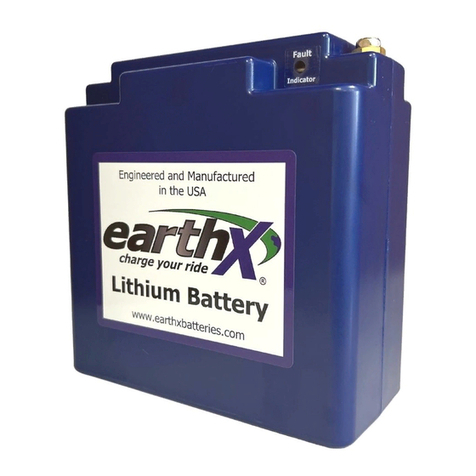
EarthX ETX Series Instruction Manual

Installation&Maintenance
Manual(IMM),ETX680-
24-TSOBattery
Copyright© 2020 EarthX, Inc. All rights reserved. The information contained in this document is the property of EarthX, Inc.
EarthX reserves the right to make changes to its documents or products without notice. It is the responsibility of each user to
ensure that all applications of EarthX’s products are as intended and safe based on conditions anticipated or encountered during
use. The EarthX logo is a trademark of EarthX, Inc
200407 Rev-

E T X S E R I E S L I T H I U M B A T T E R I E S
Revision Log
Rev
Description
Date
New
Created New
11/6/2020
I C O N K E Y
Valuable information
Caution

E T X S E R I E S L I T H I U M B A T T E R I E S
Table of Contents
Revision Log ...................................................................................... i
Overview........................................................................................... 1
Technology Inside.............................................................................1
Battery Cells....................................................................................1
BMS ................................................................................................1
Physical Layer ......................................................................................2
Protocol Definition...............................................................................3
Data Definition ....................................................................................3
Installation Requirements..................................................................4
Specifications....................................................................................4
Discharge Curves..............................................................................6
Discharge Versus Temperature.........................................................7
Self-discharge Rates.........................................................................8
Installation.........................................................................................9
Battery Installation Location............................................................9
Battery Installation...........................................................................9
Battery Vent Installation ................................................................10
Fault Monitoring Installation ..........................................................10
Voltage Monitoring (if applicable)..................................................13
Accessory Parts............................................................................13
Replaceable Parts.........................................................................13
Installer Supplied Parts .................................................................13
Operating Instruction....................................................................... 14
Maintenance.................................................................................... 14
Charging ......................................................................................... 14
Storage ........................................................................................... 15
Part Number Revision..................................................................... 16
Warranty ......................................................................................... 16
Troubleshooting .............................................................................. 16
Regulations / Standards.................................................................. 17
Terminology .................................................................................... 17
Appendix A...................................................................................... 18
DO-311A Test Summary .................................................................18
DO-160 Environmental Qualification Form .....................................19
Appendix B...................................................................................... 20
Block diagram of a typical installation. .................................................20

ETX S E R I E S L I T H I U M B A T T E R I E S
1
Overview
EarthX Lithium batteries are designed as a maintenance free replacement for the 24-volt
lead-acid or lithium starter batteries. The Starting Battery (Function) is considered Primary
in the electrical system for Category I and II part 23 Aircraft. The alternator charging system
is considered secondary. Per 14 CFR 23.1309-1E and TSO-C179b, the Failure Condition
Classification (FCC) for this TSO Battery is “Major” - unless other installations deem the
analysis lessor or greater, dependent on the function in the particular installation Aircraft.
This manual covers the TSO Article (Part) installation aspects for the ETX900-TSO Battery
to be installed on 14 CFR part 23 Aircraft. Refer to AC 20-184 for full Aircraft installation
guidance and requirements not the subject of this manual.
Failure to follow all application use, installation, charging, and storage instructions may result
in battery damage and or fire!
Technology Inside
Battery Cells
The batteries use cells made of Lithium Iron Phosphate (LiFePO4). This chemistry is one of
the highest performance and safest on the market today.
Lithium batteries are fundamentally different than lead-acid batteries. A lithium battery
voltage remains relatively constant while discharging, while voltage for a lead-acid battery
decreases. As such, 16Ah lithium battery has the equivalent “useable” capacity. What do you
mean here? Also, a lithium battery’s cranking power is stronger, for the voltage while
cranking is generally higher.
LiFePO4cells by the nature of their chemistry are 3.3 volt. 12V/24V lithium batteries are
created by using 4 cells/8 cells in series (technically it is a 13.2V / 26.4 V battery). The
typical full charge resting voltage is >13.3V for a 12V replacement battery and 26.6V for a
24V replacement battery. Another difference is that lithium cells are a dry cell technology,
where the cells are packaged individually. As such, the individual cell’s charge level will
diverge with repeated charge/discharge cycles and age. This condition reduces the
performance of the battery (reduces capacity), for the battery charge level is only as good as
the charge level of the weakest cell.
BMS
EarthX’s integrated Battery Management System (BMS) monitors each cell’s voltage. If the
voltage (charge) of a cell exceeds the others, the BMS circuits will work to reduce that cell’s
charge level. This ensures that the charge level of all the cells remains equal, even with the
high discharge (> 100Amps) and charge current (>10Amps) of your aircraft.

E T X T S O L I T H I U M B A T T E R I E S
2
The BMS has the following additional protective features; over-charge protection, over-
discharged protection (completely draining the battery), excessive cranking protection, high
temperature protection and short-circuit protection. The BMS was designed to Design
Assurance Level (DAL), C (major).
The BMS disconnects the battery from the load if it is drained to less than 3-5% remaining
charge (an over-discharge condition). An over-discharged battery typically has a voltage less
than 22V. If the BMS disconnects the battery, the voltage reading of the battery will be zero
volts. Excessive cranking protection logic includes current, temperature and time
monitoring to limit “high current use” (engine cranking) to 10 -30 seconds in any 60 second
period. If the battery terminals are “shorted” (or a low impedance load is connected across
terminals), which causes the battery volts to instantaneously drop to a very low level, the
battery will disconnect from the load to protect the cells and BMS from damage (short
circuit protection). If the BMS disconnects due to excessive cranking protection or short
circuit protection, the BMS will automatically reconnect after a cooldown period (typically 1-
3 minutes). The BMS is designed for short circuit protection > 1000 Amps.
In the event of a charging system failure where the voltage increases to above 32V, the
charging current is blocked. The time delay for this feature is 2 seconds to allow the aircraft
alternator’s over voltage protection to activate first (typically less than 100ms). This design
offers charge voltage protection greater than 100V. The discharge current (current out of
battery) is unaffected in this situation.
All components associated with main electronic battery disconnect are redundant. The
built-in redundancy ensures that no single point failure results in the battery unintentionally
disconnecting. The battery also includes a thermal run-away containment system. The
design aligns with the requirements for a FAA approved lithium battery as per RTCA
performance specification DO-311A and DO-160.
The battery’s micro-controller monitors all failure modes, and reports failures with a built-in
LED indicator, plus a discrete output and RS-232 communication link. The discrete output
for external fault monitoring is a single wire connection with a ¼” quick connect terminal.
The output is a “current sinking” type circuit (see diagram below) that can handle 100mA
(connects the discrete output to battery ground if a fault is present). This output can be
connected to an external 24V LED or general purpose discrete input of an EFIS. The fault
output has three states; fast flashing (2 seconds on/ 2 seconds off), slow flashing (5 seconds
on/ 5 seconds off) or solid. The fast flashing fault is an indication of high temperature;
temperature exceeding the normal operating or storage limits of the battery. The slow
flashing fault can indicate an improper state of charge or a problem with the cells internal to
the battery. The solid fault indicates a BMS hardware failure. See the RS-232
Communications section of this manual for more details.
RS-232 Communications
PhysicalLayer
The following defines the RS232 physical layer attributes:
Baud Rate: 1200
This manual suits for next models
1
Table of contents
Other EarthX Camera Accessories manuals
Popular Camera Accessories manuals by other brands

Trojan
Trojan GC2 48V quick start guide

Calumet
Calumet 7100 Series CK7114 operating instructions

Ropox
Ropox 4Single Series User manual and installation instructions

Cambo
Cambo Wide DS Digital Series Main operating instructions

Samsung
Samsung SHG-120 Specification sheet

Ryobi
Ryobi BPL-1820 Owner's operating manual