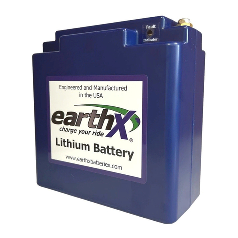
EarthX ETX900-TSO User manual

Instructions for Continued
Airworthiness (ICA), ETX900-TSO
Battery
FAA Approvals
FAA Office(s) Name Date Signature
Revision Log
Rev Description Date Approved By:
New Created New 5/12/2018 R.Nicoson/B.Olsen
A AML STC Release Draft R.Nicoson
B Incorporate FAA AEG
comments.
7/31/2020 R.Nicoson
Copyright© 2020 EarthX, Inc. All rights reserved. The information contained in this document is the property of EarthX, Inc.
EarthX reserves the right to make changes to its documents or products without notice. It is the responsibility of each user to
ensure that all applications of EarthX’s products are as intended and safe based on conditions anticipated or encountered during
use. The EarthX logo is a trademark of EarthX, Inc
180426

E T X T S O L I T H I U M B A T T E R I E S
180426
Table of Contents
FAA Approvals ................................................................................... i
Revision Log ...................................................................................... i
Table of Contents .............................................................................. 1
Overview – Purpose .......................................................................... 2
Installation Requirements .................................................................. 2
Airworthiness Limitations ................................................................... 4
Instructions for Continued Airworthiness (ICA) .................................. 5
ICA Revisions .................................................................................. 5
Battery Maintenance Requirements ................................................ 5
Aircraft Charging System Maintenance Requirements .................... 7
Battery Charging ............................................................................. 7
Battery End of Life ........................................................................... 8
Battery Storage and Handling ........................................................... 9
Battery Operation .............................................................................. 9
Normal Operation .......................................................................... 10
Abnormal Operation ...................................................................... 10
Emergency Operation ................................................................... 10
Emergencies with Aircraft Charging System as Root Cause .............................. 10
Emergencies with Battery as Root Cause ........................................................... 10
Terminology .................................................................................... 11
Reference Documents ..................................................................... 11
Appendix A (Textron Cessna 182P Installation) .............................. 12
Typical Placard – Cessna 182 ....................................................... 12
Flight Supplement -Tabular Information ........................................ 13
Normal Aircraft Charging System Operation ....................................................... 13
Abnormal Aircraft Charging System Operation ................................................... 14
Installation and Wiring Diagram - Excerpt ........................................................... 14

E T X T S O L I T H I U M B A T T E R I E S
180426
2
Overview – Purpose
This manual covers the TSO Article (Part) installation aspects for the ETX900-TSO Battery
to be installed on 14 CFR part 23 Aircraft. Installations of rechargeable lithium batteries
defined herein, are expected to meet the guidance of AC 20-184. This TSO Battery meets
the applicable TSO-C179b and is targeted for installation in 14 CFR part 23 airplanes. Refer
to AC 20-184 for full Aircraft installation guidance and requirements not the subject of this
manual.
This manual is to provide information (as required by CFR Part 23, Appendix G) to enable
maintenance personnel to maintain the ETX900-TSO battery in a part 23 airplane. This
ICA number 180426-01 covers the Cessna 182P specifics and are contained in Appendix A.
In the spirit of an AML STC, this ICA is intended for general use and reuse with specifics
contained in the appendices for a specific model. Additional models using the Model
Qualification Process (MQP) will be added to the AML-STC. Each model or series will
have a specific ICA called out by document dash number. EarthX is using the Appendix
approach to facilitate maximum reuse as suggested in AC 23-20.
The EarthX Lithium battery is designed as a maintenance free replacement for 12-volt lead-
acid or lithium starter batteries. The ETX900-TSO battery is part of the electrical system as
a Secondary function with the Alternator system being Primary in the aircraft electrical
system. The battery within this system has two subfunctions: Starting Battery and Storage
battery.
Per 14 CFR 23.1309-1E and TSO-C179b, the Failure Condition Classification (FCC) for this
TSO Battery was initially defined as “Major” during the TSO project. Other installations
may deem the analysis lessor or greater, dependent on the function in the particular
installation Aircraft. Operation in an over-voltage condition (greater than 16 volts) may
potentially result in a dangerous battery failure. Additionally, the safety of the aircraft may
be compromised, if the battery is not properly sized to provide adequate emergency power,
according to the aircraft essential system design load and duration.
Although many internal and external safety features have be designed per TSO and AC 20-
184, failure to follow all application use, installation, charging, and storage instructions may
result in battery damage and could lead to fire!
Installation Requirements
“This article meets the minimum requirements of technical standard order (TSO) C179b.
Installation of this article requires separate approval.” The article may be installed only according
to 14 CFR part 43 and the applicable airworthiness or STC requirements. Below are the installation
specific, in-service requirements as identified in EarthX’s AML STC process document 18114-03
and is not part of the TSO Part (LRU) specific certification under TSO-C179b:

E T X T S O L I T H I U M B A T T E R I E S
180426
3
a. The maximum charge rating is 80 amps, so the aircraft alternator rated output must be 80
amps or less.
b. The maximum voltage output from aircraft charging system shall not exceed 16 volts.
Thus, an automatic over-voltage protection device (OVPD) is required on the aircraft
charging system.
c. The battery fault monitoring indicator must be installed and tested.
d. The battery vent system must be installed per the aircraft model specific STC IWD
instruction (see the appendix of this manual for document details).
e. The cranking current demand should not exceed; a Peak Power (Ipp) 800/390 Amps
(+23C/-18C), Rated Power (Ipr) 600/365 Amps (+23C/-18C). Note: Old CCA spec is
Ipr at -18C.
f. The capacity demand (storage requirement) should not exceed 31 Amps for 30 Minutes.
Timely pilot identification and load shedding assumed per normal procedures. An
Electrical Load Analysis (ELA) is required.
g. The battery must be installed in such a manner and or location to limit radiant and
convection heating. The maximum short term (30 minute) environmental temperature of
battery location should be less than 65°C. The maximum short term (30 minute)
environmental temperature of battery location while the aircraft is on the ground shall not
exceed 85°C. The battery’s normal operating temperature is -30°C to 60°C.
h. The battery should be secured in the existing battery box or battery holder as detailed in
this manual and aircraft model specific STC IWD instruction (see the appendix of this
manual for document details).
For a specific aircraft installation, refer to the documentation listed in the Appendix
of this manual.

E T X T S O L I T H I U M B A T T E R I E S
180426
4
Airworthiness Limitations
The conditions and tests for TSO approval of this article are minimum performance standards.
Those installing this article, on or in a specific type and class of aircraft, must determine that the
aircraft installation conditions are within the TSO standards. The article may be installed according
to 14 CFR part 43 or the applicable airworthiness requirements. The Airworthiness Limitations
section is FAA approved and specifies maintenance required under 43.16 and 91.403 of the Title
14 of the Code of Federal Regulations.
There are no new (or additional) airworthiness limitations associated with this equipment
and/or installation.
FAA APPROVAL:
_________________________ _________________________ ____________
Printed Name/ Title Signature Dated
MARK J DALRYMPLE
Digitally signed by MARK J DALRYMPLE
Date: 2021.03.26 11:43:28 -06'00'

E T X T S O L I T H I U M B A T T E R I E S
180426
5
Instructions for Continued Airworthiness (ICA)
The supplemental Instructions for Continued Airworthiness (ICA) are required by 14 CFR
part 23 for this Article (Part) installed on Aircraft (14 CFR 23.1529 for this application and
TSO).
The Battery Functions are considered Secondary within the electrical system for each of the
Classes of Airplanes shown in Figure 2 of AC 23.1309-1E. The alternator charging system is
considered Primary for this ICA. Per AC 23.1309-1E and reference TSO-C179b, the Failure
Condition Classification (FCC) for this TSO Battery is “Major”. For this ICA and Battery
there is no complex hardware or software. However, other installations may deem the
analysis lessor or greater, dependent on the function in the particular installation Aircraft.
ICA Revisions
Updates and/or revisions to the ICA will be available from the documentation section of the
EarthX Website: www.earthxbatteries.com. Customers will be notified of a change to the
ICA via the customer’s email of record.
Battery Maintenance Requirements
The ETX900-TSO battery is a maintenance free battery with no internal replaceable
components. No inspection or testing is required for the first 24 months after purchase.
Thereafter, an annual inspection is required to ensure that the battery functions as designed
and installed for safe operation of the aircraft.
The following inspections/tests shall be performed on an annual basis (after first 24-month
period), typically during the annual inspection:
1) Visually inspect the battery for signs of damage; plastic case cracks, warped plastic or
long side of the battery is swollen.
2) Verify the battery fault monitoring LED circuit is operational. To do this, use a
wire jumper to connect the battery’s fault output wire to battery ground (see figure
inset below), and verify that the battery’s internal fault LED is lit and that the
external fault LED and/or EFIS indicator (on the instrument panel) is lit or
indicating. Alternately, if the panel mount LED is equipped with a “Push to Test”
feature, it can be used in lieu of the wire jumper method described above.

E T X T S O L I T H I U M B A T T E R I E S
180426
6
3) Ensure the battery is fully charged. Turn off the aircraft master switch and any other
battery loads, then measure the voltage at the battery terminals. A fully charged
battery should be 13.4 volts or greater. If not connect an Optimate TM291 (5 amp)
or TM275 (9.5amp) battery charger to the battery and leave the charger “On” until
the charge lights (Save, Charge and Optimize LEDs in the center of the charger) are
extinguished.
4) After fully charging the battery in the previous step, allow the battery rest over-night
(minimum of 12 hours) without any load applied to the battery. Verify the battery is
“holding a charge” by confirming the voltage is greater than 13.4 volt.
5) Verify the battery capacity. A battery’s current capacity as compared to its original
capacity is an indication of the battery’s remaining service life. A battery with greater
than 80% of its original “rated” capacity is consider fit for continued service. If the
battery capacity is less than 80%, then it must be replaced. Alternately, if the batteries
tested capacity is capable of supporting the aircraft’s emergency load for the required
amount of time it is consider fit for continued service. It is recommended that the
article be replaced after 6 years of service. To test the battery capacity:
a. Fully charge the battery with an appropriate charger
b. Turn on all electrical loads for flight operation and start a timer.
c. Measure and record the battery’s discharge amps using a DC clamp-on
current meter at the positive terminal of the battery.
d. Using the measured amps in the previous step and the battery’s nameplate
rated capacity (in Ah), calculate the time to discharge the battery to 80%.
Time to discharge 80% (Hours) = ∗ .
For Example (16 Ah Rated Capacity, 5 amp measured discharge rate)
Time to discharge 80% = ∗ .
= 2.56 hours
e. Terminate the test after the number of hours calculated in the previous step
has expired or if the battery is over-discharged (shuts off discharge current).
If the battery is still supplying power at the termination of the test, then the
battery’s capacity is greater than 80%. If the battery’s capacity is greater than
80% of it rated or capable of supporting the aircraft’s emergency load for the
required amount of time, then the battery has passed the test.
f. Fully charge the battery with an appropriate charger.

E T X T S O L I T H I U M B A T T E R I E S
180426
7
6) Verify battery terminals are clean and terminal screws are properly secured (torque to
45in-lbs).
7) Visually inspect the vent tubes to ensure they are not blocked (plugged, pinched or
kinked).
8) Verify the battery box and or battery restraint system is in good working order. The
foam insert (190531) is used to loosely hold the battery in a corner on the opposite
end of the box from drain hole (up to +-1/8” of movement sided to side or front to
back is ok; as measured at the bottom of the box).
9) Test complete, record in Aircraft Logbook with inspection info or storage log.
Aircraft Charging System Maintenance Requirements
An annual inspection (check and/or test) is required for the voltage regulator and Over-
Voltage Protection Device (OVPD) or System (OVS) of the aircraft charging system for safe
operation of the battery and aircraft electrical system. The regulator and OVPD or OVS
may physically be separate devices or in a single housing. Follow the regulator and OVP
manufacturer’s ICA or maintenance instructions for annual checks and or tests.
Battery Charging
If at any time the aircraft will not start, or the battery seems low, or the voltage is less than
13.2 volt, charge it for the recommended time and charge rates shown below and disconnect
the charger when charging is complete. The recommended and maximum charge rate is
specified on the top label of the battery. Never exceed the maximum charging amps for
your battery.
This table shows typical charging times for the battery:
Model Charging Amps Charging Time
ETX900-TSO 5 amp (TM291 Charger) 3 hour
10 amp (TM275) 1.5 hour
Lithium batteries have a very low self-discharge rate which means the battery, if
disconnected from the aircraft, could “hold its charge” for over a year. However, some
aircraft may have systems that use a small amount of power with the “Master switch” off. In
those cases, we recommend disconnecting a battery cable from the battery during long term
storage (greater than 6 months).
Only an approved battery charger shall be used:
Optimate TM291 (5 amp) or TM275 (9.5amp)
If the battery has been over-discharged and “disconnected”, the voltage at the battery
terminal should be near zero volts if the battery still has a load on it. If the battery is
disconnected from the load it will automatically reconnect and the terminal voltage return to
> 9volts (remove the load by removing the positive or negative cables from the battery). In

E T X T S O L I T H I U M B A T T E R I E S
180426
8
this case, simply connect the battery to a charger to restore charge (charge with 1-10 amps
for 20-30 minutes), and then re-check the voltage. If the voltage is 12.8V or greater and
holding a charge, the battery should be ok and can be fully charged. If the battery voltage
does not return to >9 volt after removing any and all load. Then (step 1) connect the
Optimate battery cables to the battery (red clamp to positive and black clamp to negative),
next (step 2) plug the charger power cord into AC outlet. The charger should startup and
go into the “Save” charging mode. If not contact EarthX technical support.
If using a Ground Power Unit (GPU), the current rating or current setting SHALL NOT be
more than the max charge rate stated on the battery label or in this manual. It is
recommended that a warning label is placed next to the GPU plug stating the max current
allowed.
Never jump start from a car size battery or larger!
Never charge a faulty battery (a battery that will not accept a charge or hold a
charge).
Never use the de-sulfate setting on your charger. Be sure the charger’s output
voltage level does not exceed 15V. If the charger does not display the voltage reading, then
use a voltmeter to check the voltage while charging.
If the battery gets hot while charging, discontinue charging and use.
Do not charge battery in temperatures above 140 degrees F (60C), or in direct
sunlight.
When charging a battery, place it on a non-flammable surface, and remove any
flammable items nearby.
For maximum battery and starting system life, do not crank an engine for
more than 15 seconds within any 1 minute period.
Battery End of Life
The ETX900-TSO battery expected life is 6 years. However, the following conditions
indicate battery end-of-life and the battery shall be replaced to ensure continued
airworthiness:
Insufficient capacity per annual maintenance requirements above
Insufficient power to crank engine

E T X T S O L I T H I U M B A T T E R I E S
180426
9
On-going battery fault indication (refer to the “Battery Operation” section of this
manual or the “Troubleshooting” section of the Installation and Maintenance
Manual (IMM), 180407
Will not hold a charge (>13.2 volts a week after charging the battery to full charge)
6 years of in-aircraft service
At battery end-of-life contact EarthX for replacement options.
Batteries can be recycled at any location accepting lithium ion type batteries. Drain battery and or
cover terminals with electrical insulating tape prior to recycling. For recycling information and
where to recycle check this website (www.call2recycle.org/).
Battery Storage and Handling
If the Aircraft is to be put in storage for an extended period of time (> 6 months),
disconnect the battery cable to eliminate drain from the Aircraft’s electrical system. A fully
charged battery can be put in storage for up to a year without charging, but should be
charged and inspected annually.
Our batteries can be stored at temperatures between -40°C to +70°C. Our batteries have no
liquid inside and will not freeze.
Special care must be taken in the handling, shipping, and storage of rechargeable lithium
batteries. As a result, installers, end users, and personnel involved in the maintenance, and
disposal of rechargeable lithium batteries requires training in the special characteristics
related to rechargeable lithium battery safety. Leaving battery output terminals or leads
exposed may result in external short-circuiting of the battery during shipping, handling,
testing and installation. Terminals of batteries shall be covered with non-conductive
protective devices to avoid any possibility of shorting during handling, shipping, and storage.
Do not incinerate or expose to open flames!
The MSDS is available on EarthX’s website.
Always follow the manufacturers recommended safety precautions and
procedures.
Do not incinerate or expose to open flames!
Battery Operation
The instruction given here are generic and are NOT the sole instruction for a particular
aircraft. For a specific aircraft, refer to the Appendices of this manual.

E T X T S O L I T H I U M B A T T E R I E S
180426
10
Normal Operation
Under normal operating conditions the battery performs as any lead acid battery, storing
energy from the charging system and suppling it when the charging system is off.
Abnormal Operation
i. If the battery fault indicator LED turns on and remains on solid, it is an indication
that the BMS electronics has failed. In this case, the battery should continue to
provide power as normal, but it is recommended that the pilot shall pay more
attention to the aircraft bus voltage or current. As long as the bus voltage or current
remains normal, this is not an emergency. The battery shall be replaced prior to any
future flights.
ii. If the battery fault indicator LED slowly cycles 5 seconds on \5 seconds off, and the
aircraft bus voltage is within its normal range, it is an indication that one or more
cells in the battery is failing to charge up equal to others (cell charge level imbalance).
The slow flashing fault may come on briefly (less than 60 minutes) during or
following periods of high current charging (greater than 50 amps). In this case the
battery should continue to provide power as normal, but the pilot shall pay more
attention to abnormal aircraft bus voltage or current. However, the battery shall be
maintained or replaced prior to any future flights.
iii. If the battery fault indicator cycles 2 second on\2 second off is an indication of high
temperature; temperature exceeding the normal operating or storage limits of the
battery. As long as the bus voltage \current remains normal, this is not an
emergency.
Emergency Operation
Emergencies with Aircraft Charging System as Root Cause
i. If the battery fault indicator LED slowly cycles 5 second on \5 second off, and the
aircraft bus voltage is greater than 15 volts, or the high voltage warning light is on, it
is an indication that the aircraft’s charging system voltage regulator has failed. If the
aircraft charging system voltage exceeds 16 volts, then the charging system’s
automatic over voltage protection device (OVPD) has failed to operate. In these
cases, the battery is functioning normally, but the pilot shall turn off or isolate the
charging system to eliminate the bus over-voltage event. Additionally, the pilot
should make preparations to land prior to the battery’s reserve capacity being
depleted.
ii. If the battery fault indicator LED slowly cycles 5 second on\5 seconds off and the
aircraft bus voltage is less than 12.8 volt or the low voltage warning light is on, or the
amp meter is indicating no current from the alternator; it is an indication that the
aircraft’s charging system has failed. In this case, the battery is functioning
normally, but the pilot shall make preparations to land prior to the battery’s reserve
capacity being depleted. Note, below 12.8 volt the battery is already deeply drained
(as much as 80%).
Emergencies with Battery as Root Cause
i. If the battery fault indicator LED comes on “solid” it is an indication of a Battery
Management System (BMS) electronics failure. If the fault indicator remains on and
the aircraft charging system exhibits abnormal behavior (i.e. current or voltage

E T X T S O L I T H I U M B A T T E R I E S
180426
11
fluctuations or voltage above 15 or voltage below 13). The pilot should terminate
the flight and land as soon as possible.
ii. If the battery fault indicator LED cycles 2 second on\2 seconds off and there is
vapor and or smoke exiting the battery vent tubing, it is an indication that the battery
is in a thermal runaway. The pilot should terminate the flight and land as soon as
possible.
A sustained fault can indicate a serious issue with the battery or aircraft charging system that requires
attention. Discontinue use until the issue is resolved and the battery no longer indicates a fault.
Continued use of a faulty battery can result in a cell rupture, and the release of flammable vapors,
and or smoke (through vent system and to outside the aircraft).
Terminology
The following table describes the terminology used in this document.
Ah
Amp-Hour is a unit of measure of charge that can be stored in a
battery.
BMS
The Battery Management System refers to the collection of
electronics responsible for monitoring and controlling the cell charge
level, providing over charge protection and over discharge protection
Cell
A single encased electrochemical unit (one positive and one negative
electrode) which exhibits a voltage differential across two terminals.
OEM
Original Equipment Manufacturer
IEC
International Electro-Technical Commission on safety standards.
Reference Documents
AC 20-184
Dated 10/15/15
(or latest rev)
Guidance on Testing and Installation of Rechargeable
Lithium Battery and Battery on Aircraft
AC 43.13-1B CNG1
Dated 9/8/98
(or latest rev)
ACCEPTABLE METHODS, TECHNIQUES, AND
PRACTICES - AIRCRAFT INSPECTION AND
REPAIR

E T X T S O L I T H I U M B A T T E R I E S
180426
12
Appendix A (Textron Cessna 182P Installation)
For complete installation details see document ETX900-TSO-IWD-C182
The parts required for installation are:
Item
Qty Part Number Part Description
1 1 ETX900-TSO EarthX Battery
2 1 190531 35 Ah Battery Box Insert
3 1 11MM12 Amber 12 Volt LED
4 1 200208 Fault Indicator Placard
5 - AR Wire Retention Ties/Hardware/Insulation
per AC 43.13-1B, Chapter 11
Below is picture an image of the battery and insert installed in the existing battery box.
Typical Placard – Cessna 182
The Cessna (Textron) 182 Aircraft does not have an Airplane Flight Manual, therefore a
Placard is required in lieu of an AFMS (See Install Kit – Placard P/N: 200208).

E T X T S O L I T H I U M B A T T E R I E S
180426
13
Placard:
Flight Supplement -Tabular Information
The table below is a summary of the battery’s three fault codes; solid, slow cycling or fast
cycling. The fault codes are considered cautionary or advisory ONLY. The panel mount
LED shall be yellow or amber in color.
Normal Aircraft Charging System Operation
The fault codes when active during normal electrical system operation require no pilot
corrective action.
LED Light Voltage/Current
Possible Cause Recommended Action
Slow Flashing
(5s on/5s off)
12.8-14.6V/
Normal
Cell to cell charge level
imbalance
No pilot action is required in flight.
The pilot should report battery
problem to maintenance
personnel when back on the
ground (note how long the fault
light was on).
Solid Light Any voltage or
current BMS electronics problem
No pilot
action is required in flight.
The pilot should report battery
problem to maintenance
personnel when back on the
ground.
Short Flashing
(2s on/2s off)
Any voltage or
current
High battery temperature
(> 85°C / 185°F)
No pilot action is required in flight.
The pilot should report battery
problem to maintenance
personnel when back on the
ground.

E T X T S O L I T H I U M B A T T E R I E S
180426
14
Abnormal Aircraft Charging System Operation
The battery fault codes when active during abnormal electrical system operation and or
electrical system warning require pilot corrective action.
LED Light
Voltage/Current
/Other Possible Cause Recommended Action
Slow Flashing
(5s on/5s off)
Less
than 12.8V/
No charge
current amps/
low voltage or
alternator out
warning light on
Charging system is not
functioning (Battery over-
discharged)
Pilot to make preparations to land
prior to the battery’s reserve
capacity being depleted.
Slow Flashing
(5s on/5s off)
Greater than
15V / high
charge amps/
high voltage
warning light on
Over-charging (due to
faulty charging system)
Pilot to shutoff charging system
immediately, and make
preparations to land prior to the
battery’s reserve capacity being
depleted
Solid Light
Voltage or
current
fluctuations
BMS electronics issue Pilot should terminate the flight
and land as soon as possible.
Installation and Wiring Diagram - Excerpt
This is a simple battery installation. For reference: Interface, Location and Wire routing:
For full BOM and details see (ETX900-TSO-IWD-C182)

E T X T S O L I T H I U M B A T T E R I E S
180426
15

E T X T S O L I T H I U M B A T T E R I E S
180426
16
Other manuals for ETX900-TSO
1
Table of contents
Other EarthX Camera Accessories manuals