EASEPAL EC-570 Manual

中国·厦门蒙发利科技有限公司
Xiamen Comfort Science & Technology Group Co., Ltd
EC-570
Maintenance Service Manual
Model:EC-570 Sereies Voltage:220-240VAC
By Customer Service Department

1
厦门蒙发利科技公司客户服务中心
Maintenance Service Manual
Contents
I……Specifications ………………………………………………………2
II…..Appearance of the chair ……………………………………………3
III… Name and functions of components (remote controller)……………4
IV….Malfunction catalog…………………………………………………5
V…...Troubleshooting flow chart…………………………………………8
VI….Terminals on the main PCB ………………………………………13
VII…Maintenance of the back rest………………………………………14
VIII…..Maintenance of the seat part ……………………………………27
IX……Maintenance of the foot rest ……………………………………36
X…..Electrical wiring diagram …………………………………………39
XI…..Schematic diagram of the main PCB ……………………………40
XII…Contact us…………………………………………………………41
Model EC-570

2
I. Specifications
Items Specifications
Product Series SMART MATE
Model NO. EC-570B/ OG2800
Rated voltage 220~240VAC
Rated frequency 50Hz
Power consumption 150W
Rated time 15 minutes
Total time 60 minutes
When packing:1205×780×840(mm)
When reclined:2000×750×700(mm)
Dimensions
(Length × width × height)
When not reclined:1360×750×1150(mm)
N.W.: 65kg
Weight G.W.: 83kg
Remote controller: 1 m
Line length Power cord: 2.2 m
Temperature: 10~40 ℃
Usage condition Humidity:30~85 %RH
Temperature: 20~60 ℃
Storage condition Humidity: 30~85 %RH
Safeguard Over-current protector

3
II.Appearance of the chair
Remote controller
Arm rest
Foot rest
Wrench for extending foot restSide board
Seat pad
Holder of remote
controller
Pillow
Back pad
Rear cover
under the seat
Front cover
of back rest
Rear cover of
back rest
Castor

4
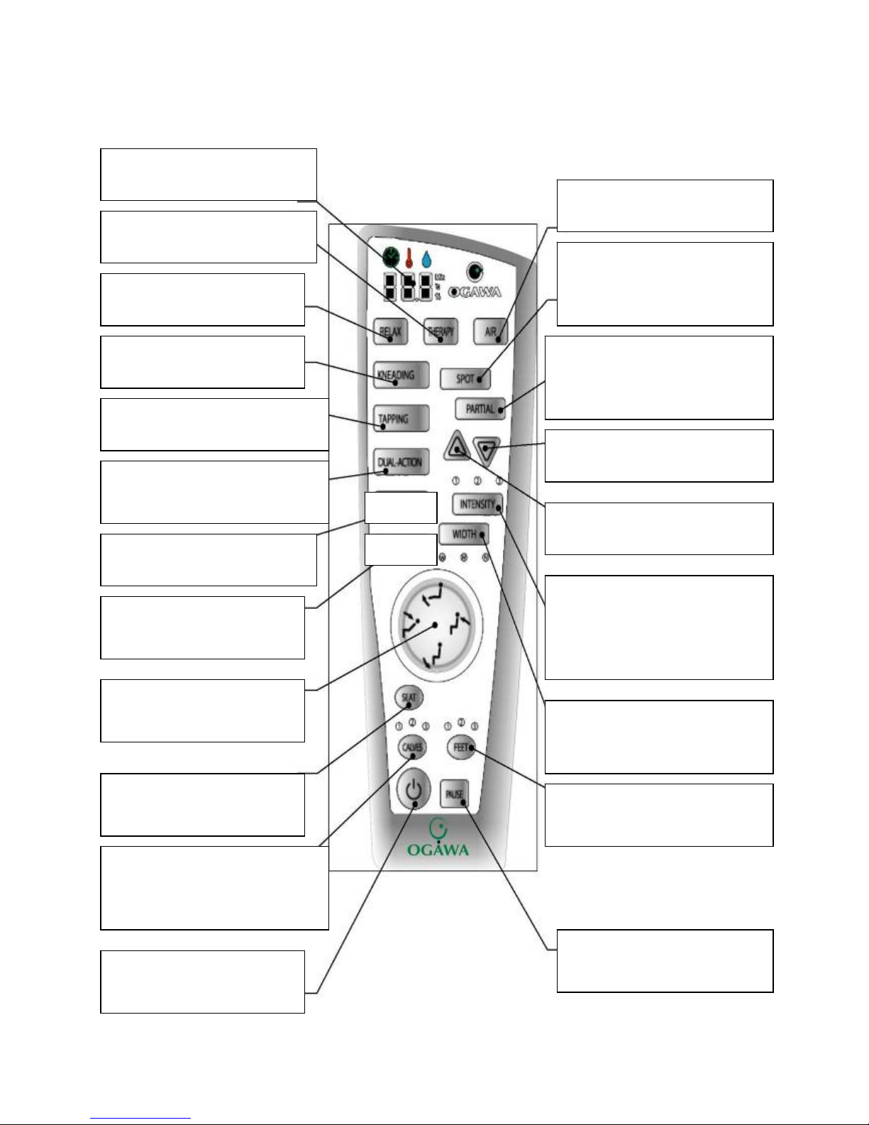
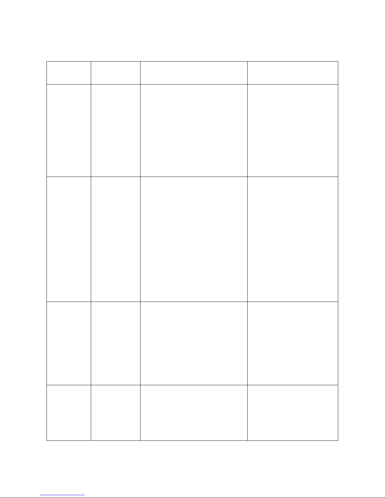
III.Name and functions of components (remote controller)
Keys for actuators
Allows adjusting the angle of
back rest and foot rest
LCD display
Displays time and temperature
RELAX key Allows starting
up automatic kneading program
WIDTH adjust key
Width between knead balls can be
adjusted at 3 levels. Only limited to
TAPPING, ROLLING
INTENSITY adjust key
Massaging intensity can be
adjusted at 3 levels. Only limited to
KNEADING, TAPPING, SWEDISH,
DUAL-ACTION, RELAX, THERAPY,
AIR
ON/OFF
Allows starting and stopping the
chair.
THERAPY key Allows starting
up automatic tapping program
AIR key Allows starting up
automatic charging program
SEAT key Allows starting
vibrators and charging gas-bags
in the seat pad.
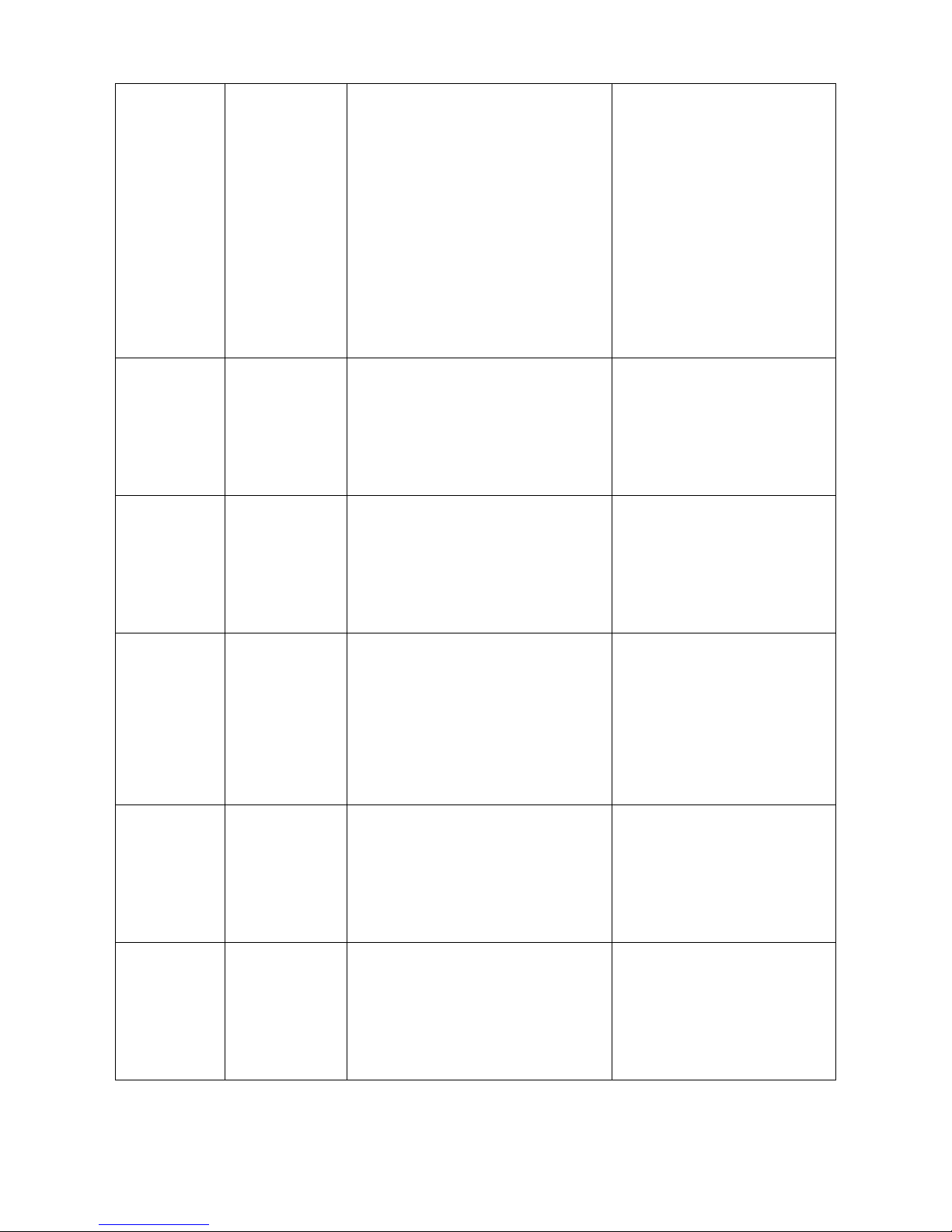
CALVES key Allows starting
vibrators and charging gas-bags in
the calves rest. Intensity can be
adjusted at 3 levels
FEET key Allows charging
gas-bags in the foot rest. Intensity
can be adjusted at 3 levels
PAUSE key
All the action will be broken off
by this key
SPOT key Allows starting spot
massage just in the current
position. Position can be adjusted
by UP and DOWN
PARTIAL key Partial massage
taking the current position as the
center with height 16 cm. Center can
be adjusted by UP and DOWN
DOWN key Mechanical main unit
will run down by holding down it.
UP key Mechanical main unit will
run up by holding down it.
KNEADING key Full-back
mode, intensity can be adjusted.
TAPPING key Full-back mode,
intensity and width can be adjusted.
DUAL-ACTION key Full-back
mode of kneading and tapping,
intensity can be adjusted.
ROLLING key Full-back mode,
width can be adjusted.
HEATING key Allows starting
and stopping the heating in back
pad and foot rest
Heating
Rolling

5
IV. Malfunction catalog
Common Trouble and processing Methods are listed as follow:
Serial NO. Phenomenon Description Maintenance Methods
01 No Function
When Starting.
The LCD isn’t illuminating:
①Fuse melts (in the Power Source Box
or on the main PCB).
②Power supply circuit poorly
connected.
③EMC Board fails.
④main PCB fails.
①Replace Fuse.
②Replace Power Box.
③ Replace EMC Board.
④Replace main PCB.
02 No function
when starting.
The LCD is illuminating:
①Mechanical switch fails or it’s wire is
opened.
②Up or Down Stroke Photo-electricity
fails.
③Main PCB fails.
④Kneading is on without pressing any
key when starting and no response by
pressing other keys.
①Replace mechanical switch or
it's wire.
②Replace Stroke Photo-
electricity.
③Replace the main PCB.
④Width Inspection Board of
PCB fails, replace it.
03 No Width
switchover.
①The terminals of Width Inspection on
main PCB and wires are poorly
connected.
②The terminals of Width Inspection on
massage mechanical and wires are
poorly connected.
③Width Inspection fails.
④Main PCB fails.
①&②Plug the terminal securely
or replace the wires.
③Replace Width Inspection.
④Replace the main PCB.
04 No Partial
Function.
①Height Inspection Terminal or wire
poorly contacts.
②Height Counting Subassembly fails.
①Plug the terminal securely or
replace the wires.
②Replace Height Counting Sub
-assembly.

6
05 No Rolling.
①Terminal or Wire Poorly Contacts.
②Down-stroke Photo-electricity
Subassembly Fails.
③Up-stroke Photo-electricity
Subassembly Fails.
④Rolling Motor Fails.
⑤Main PCB Fails.
①Plug the terminal securely or
replace the wires.
②Replace Down-Stroke Sub-
assembly.
③Replace Up-Stroke Sub-
assembly.
④Replace Rolling Motor.
⑤Replace main PCB.
06
No kneading.
①The terminals on main PCB and
wires are poorly connected.
②Kneading motor fails.
③Main PCB fails.
①Plug the terminal securely or
replace the wires.
②Replace the kneading motor.
③Replace main PCB.
07 No tapping.
①The terminals on main PCB and
wires are poorly connected.
②Tapping motor fails.
③Main PCB fails.
①Plug the terminal securely.
②Replace the tapping motor.
③Replace main PCB.
08
No response
when pressing
the keys on the
remote
controller.
①The terminals and wires are poorly
connected.
②The PCB in the remote controller
fails.
①Plug the terminal securely or
replace the wires.
②Replace the remote controller.
09
Back rest cannot
be reclined or
raised
①The terminals of reclining actuator
and wires are poorly connected.
②The reclining actuator fails.
③Main PCB fails.
①Plug the terminal securely.
②Replace reclining actuator.
③Replace main PCB.
10
Foot rest
cannot be raised
or lowered.
①The terminals of foot rest actuator
and wires are poorly connected.
②The foot rest actuator fails.
③Main PCB fails.
①Plug the terminal securely.
②Replace foot rest actuator.
③Replace main PCB.

7
11
No vibration by
the motors in the
seat-pad.
①Print motors fail.
②The terminals and wires are poorly
connected or the wires fail.
③Main PCB fails.
①Replace the print motor.
②Plug the terminal securely or
replace the wires.
③Replace main PCB.
12
No vibration by
the motors in the
Foot Rest.
①Print motors fail.
②The terminals and wires are poorly
connected or the wires fail.
③Main PCB fails.
①Replace the print motor.
②Plug the terminal securely or
replace the wires.
③Replace main PCB.
13 No gas charging
in the seat-pad.
①The terminal of the snuffle valves and
wires are poorly connected.
②The snuffle valves fail.
③The inflator pump fails.
④Main PCB fails.
①Plug the terminal securely.
②Replace the snuffle valves.
③Replace the inflator pump.
④Replace main PCB.
14 No gas charging
in the foot rest.
①The terminal of the snuffle valves and
wires are poorly connected.
②The snuffle valves fail.
③The inflator pump fails.
④Main PCB fails.
①Plug the terminal securely.
②Replace the snuffle valves.
③Replace the inflator pump.
④Replace main PCB.
15 No heating in the
back pad
①The terminal of the heating and main
PCB are poorly connected.
②The connectors of heating on the top
of the back rest are poorly connected.
③Heating leaf fails.
④Main PCB fails.
①Plug the terminal securely.
②Connect the connectors
securely.
③Replace the heating leaf.
④Replace main PCB.
16 No heating in the
foot rest
①The terminal of the heating and main
PCB are poorly connected.
②Heating leaf fails.
③Main PCB fails.
①Plug the terminal securely.
②Replace the heating leaf.
③Replace main PCB.

8
V. Troubleshooting flow chart
Notes for repairing chair or replacing parts:
①Make sure the power is OFF before tearing down the wires, moving terminals or replacing
parts.
②Semiconductors (such as IC and others) are very easy to be damaged by static, so when you
touch the PCB, please make sure your body is grounding (by wearing a girding static ring), or
your hands are touching with earthing grip (household electrical appliances putting to earth, such
as fridges, washers and so on) to release all static of the body.
1. No function when starting.
N Y
Y N
Y
否
是N
N
Y
Y Y
N
N
N
Y
否
N
Is the LCD
illuminating? Is the fuse melted? Replace fuse.
Are the terminals of Up
and Down Stroke
Subassembly connected
securely?
Is the power cord
open-circuit?
The switches of Up and Down
Stroke Subassembly fail or not?
The EMC Board
fails or not?
Replace power
cord.
Replace it.
Connect
securely.
Replace
Is kneading on without pressing any
key when starting?
Width Inspection
Board fails or not?
Replace main PCB.
Replace Width
Inspection Board.

9
2. No width switchover.
N
Y
Y
N
3. No function(fixed-spot or partial)
N
Y
Y
N
4. No rolling
N
Y Y
N
Y
N Y
N
Are the terminals of Width Inspection Board and main
PCB connected securely? Connect securely.
Width Inspection Board fails or not? Replace it.
Replace main PCB.
Are the terminals of Height Inspection Board
and main PCB connected securely? Connect securely.
Height Inspection Subassembly fails or not? Replace it.
Replace Main PCB.
Are the terminals of rolling motor wire and
main PCB connected securely? Connect securely
Rolling motor fails or not Replace the motor
Up stroke Photo-electricity subassembly fails or not Replace it
Down stroke Photo-electricity subassembly fails or not Replace it
Replace main PCB

10
5. No kneading
N
Y
Y
N
Y
N
6. No tapping.
N
Y
Y
N
7. Remote controller doesn’t work.
N
Y Y
N
Are the terminals of kneading motor wire and main
PCB connected securely? Connect securely.
Kneading motor fails or not?
Width Inspection Board fails or not?
Replace main PCB.
Replace the motor.
Replace it.
Are the terminals of tapping motor wire and main
PCB connected securely? Connect securely.
Tapping motor fails or not? Replace the motor.
Replace main PCB.
Are the terminals of remote controller wire and
main PCB connected securely? Connect securely.
The conductive rubber fails or not? Replace it.
Replace the remote controller.

11
8. Actuator doesn’t work.
N N
Y Y
Y Y
N N
9. No vibration.
N N
Y Y
否N N
Y Y Y Y
N N
Are the terminals of
reclining actuator and main
PCB connected securely?
Connect
securely.
Are the terminals of foot rest
actuator and main PCB
connected securely?
Connect
securely.
The reclining actuator
fails or not? Replace it. The foot rest actuator
fails or not?
Replace it.
Replace main PCB.
Are the terminals of
print motors in the seat
pad and main PCB
connected securely?
Are the connectors in
the middle of the wire
connected securely?
Are the terminals of print
motors in the calves-rest
and main PCB connected
securely?
Are the connectors in
the middle of the wire
connected securely?
Replace main PCB.
Connect
securely. Connect
securely.
Print motor fails or not? Print motor fails or not?Replace it. Replace it
Connect
securely. Connect
securely.

12
10. No gas charging.
N N
Y Y
Y Y
N N
N N
Y Y
YY
N N
11. No Heating in the back pad and foot rest.
Common trouble about electric control and processing methods of EC-570B are mentioned above.
It is for indication only.
Are the terminals of snuffle
valve for bags in the seat
pad and main PCB
connected securely?
Snuffle valve fails
or not?
Are the terminals of snuffle
valve for bags in the Foot
Rest and main PCB
connected securely?
Snuffle valve fails or not?
Connect
securely. Connect
securely.
Are the terminals of
inflator pump and main
PCB connected securely?
Replace Replace it.
Replace it. Replace it.
Are the terminals of inflator
pump and main PCB connected
securely?
Connect
securely.
Connect
securely.
Inflator pump fails or not? Inflator pump fails or not?
Replace main PCB.
The power is supplied to the
heating leaf or not?
The connectors of the
heating are connected
securely or not?
Replace the main PCB
The terminal of the heating leaf on the
main PCB is connected securely or not?
Replace the heating leaf
Connect them securely.
N
Y
N
Y
Y
Connect it securely.
N

13
VI. Terminals on the main PCB
Terminal of rolling,
kneading and tapping
motors.
Terminal of the
foot rest actuator
Terminal of the
reclining actuator
Terminal of up and
down stroke photo-
electricity.
Terminal of Height
Inspection.
Terminal of width
inspection.
Terminal of remote
controller.
24VDC voltage
input terminal.
23VAC voltage
input terminal.
Terminal of
inflator pump.
Terminal of
snuffle valves.
Terminal of
vibrators
Terminal of
snuffle valves.
12VDC voltage
input terminal.

14
Warning: please make sure the massage chair is POWER OFF before maintenance and repair.
As the voltage is 220-240VAC, please make sure the plug is removed from outlet for safety
before processing operations as follow.
VII. Maintenance of the back rest
1. Disassembly of the back pad
①You can find a zip of the back pad on the top of the back rest.
②Unzip, and disconnect the connector of heating leaf, then the back pad can be removed.
③If it’s damaged, a new one should be replaced. If the heating leaf fails, you can replace it too.
④Proceed in the reverse order of disassembly when replacing a new one.
2. Disassembly and replacement the rear cover of the back rest
If disfiguring damage or crack happened, you can proceed as follow:
①Find 4 pieces of screws fixing the rear cover.
②Slacken and remove them with a plus screwdriver.
③Then the rear cover can be removed.
④If it’s damaged, a new one should be replaced.
Attention: Take care not to damage the rear cover to avoid bad external appearance. Proceed in the reverse order
of disassembly when assembling the rear cover.
Zip of the back pad
Screws tightening the rear cover
(4pcs)
Heating leafConnector of heating leaf

15
3. Disassembly of the back rest
①Release the stopper at the bottom of back rest, turn down the back rest forward.
②Slacken and remove the screws fixing the rear cover of seat part. Pull out the rear cover. Disconnect the
connector of back rest on the main PCB.And slacken and remove the screw fix the ground wire.
③Remove split pin, draw out flat head rivet securing the link rod and Y-type joint with nipper pliers to separate
the reclining actuator from the back rest.
④Raise the back rest to the upright position, then pull it up to separate the back rest.
Tool:nipper pliers
Screws fixing the rear cover of seat partTurn down the back rest forward
Flat head rivet securing the link
rod and Y-type joint
Raise the back rest to the
upright position

16
4. Disassembly and replacement of the front cover of the back rest
If disfiguring damage or crack happened, or the inside
cloth is damaged, you can proceed as follow:
①After disassembling the rear cover, you can find 6 pieces
of screws fastening the front cover to the back frame.
②Slacken and remove the screws with a plus screwdriver.
③Then the front cover can be removed.
④You should proceed in the reverse order of above operation if replacement needed.
Tool: a plus screwdriver
5. Disassembly of the electric filter of the motor
①Release the stopper at the bottom of back rest, turn down the back
rest forward. Disassemble the rear cover.
②You can find a box of the filter at the bottom of the massage mechanism.
③Cut the cable ties tightening the wires on the sheet-metal with wire cutters.
④Slacken and remove the screws tightening the upper and lower cover of the box.
⑤The PCB and lower cover are fixed to the sheet-metal
with 2 pieces of screws. Slacken and remove the screws.
Screws tightening the front cover
Separate the front cover from the frame
The top screws
Cable ties tightening
the wires
Screws tightening the upper and
lower cover ST3*8 4PCS

17
⑥If the PCB fails, cut the wires and cable ties tightening the wires, then
replace a new one. Then connect the wires and secure it with line insulators.
⑦Proceed in the reverse order of disassembly when assembly.
Tool: a plus screwdriver
6. Disassembly of mechanical main unit
Attention: This method can be applied when the rolling motor is OK.
If the rolling motor fails, you can refer to 7.2 mentioned below.
①Slacken and remove the screw bolts, 8 pieces, fixing the cross beam
on the guide rails with a plus screwdriver.
②Cut the cable ties around the box of electric filter, find the wires
of the kneading motor, rolling motor and height inspection,
remove the line insulators with nipper pliers, disconnect the wires.
Bear in mind the connection of the wires to avoid confusion.
( The wires with blue sleeve is connecting to kneading motor,
and the red to rolling motor)
③Pull out the terminal of the width inspection, cut the cable ties
tightening the wire. Cut the wire leading to the electric filter with wire cutters.
④Find the wires of the rolling motor, connect to the wiring terminal of
24VDC (a little lower can be accepted) power supply. Turn on the power
to elevate the mechanical main unit, until it runs out of the guide rails.
⑤Then you can do what you want to the mechanical main unit.
⑥Proceed in the reverse order of disassembly when assembly.
Tools: a plus screwdriver, nipper pliers, wire cutters,
24VDC power supply
Screw bolts fixing the cross
beam
The cross beam is removed
Close-end
The PCB and lower cover are fixed
to the sheet-metal

18
7. Replacement of the kneading, tapping and rolling motors
Attention: The voltage of this massage chair is high and the motors are rotating in high speed, so make sure the
power is OFF before disassembly. For safety, you should remove plug from outlet.
7.1 Kneading motor(DC -24V)
①Disassemble the rear cover of the back rest, and find the belt
at top of the massage mechanism, then loosen the belt as shown
in the picture.
②Find the wire of kneading motor, and cut the cable ties
tightening the wire with wire cutters.
③Remove the line insulator covering the wires with nipper pliers, then disconnect the wires.
④Find 4 pieces of screws fixing the kneading motor to the sheet-metal, slacken and remove the screws with a
plus screwdriver.
⑤Replace a new one if it does work.
⑥Proceed in the reverse order of disassembly when replacing a new one.
Tools: aplus screwdriver, nipper pliers
7.2 Rolling motor(DC -24V):
If the power of rolling motor is supplied from main PCB and the wires between main PCB and the rolling
motor are OK, but the rolling motor doesn’t run. In this situation, there must be something wrong with the rolling
motor or reduction box. You can follow the following instruction to replace them.
Tools: a plus screwdriver, minus screwdriver, nipper pliers, wire cutters, shifting spanner, inner hexagon
spanners, 24VDC power supply
1. First, disassemble the cover of back rest. You don’t need to disassemble the whole back rest from the seat part.
2. Slacken and remove the screw bolts and nuts fixing the cross beam on the guide rails with a plus screwdriver
Screws fixing the
kneading motor
ST5*12
Disconnect the wires
Loosened belt
Tools needed and the
kneading motor taken off

19
and a spanner. Take away the cross beam.
3. Slacken and remove the screw bolts and nuts, on both sides, fixing the plastic blocks in the guide rails with a
plus screwdriver and a spanner. Take away the plastic blocks.
4. Cut the cable ties around the box of electric filter, find the wires of the kneading motor, rolling motor and
height inspection, remove the close-end wire connectors with nipper pliers, disconnect the wires. Bear in mind
the connection of the wires to avoid confusion. (The wires with blue sleeves is connecting to kneading motor,
and the red to rolling motor.) Pull out the terminal of the width inspection, cut the cable ties tightening the wires.
Cut the wire leading to the electric filter with wire cutters. Make sure that there is no resistance when we pull
out the mechanical main unit with wheels.
5. Slacken and remove the screw bolts fixing the cover of the rolling motor on the reduction box with a inner
hexagon spanner, then the cover can be removed.
6. Pry the L-shaped sheet-metals on the side of the rolling motor with a minus screwdriver, and take them out.
Disassemble the cross beam Disassemble the plastic blocks
Close-end wire connectors
Screw bolts fixing the cover Pry the L-shaped sheet-metals L-shaped sheet-metal
Table of contents
Other EASEPAL Massager manuals
Popular Massager manuals by other brands

Human Touch
Human Touch HT-5270 troubleshooting guide

SuperiorSleep EXPERIENCE
SuperiorSleep EXPERIENCE Infinity Deluxe SMART CHAIR-X3 user manual

Lanaform
Lanaform Skin Mass LA11022002 manual

Peter Bausch
Peter Bausch 0345 Instructions for use

Vitek
Vitek VT-1393 W Manual instruction

Gaiam
Gaiam Wellbeing Trigger Point Massage Ball Instructions for use