中国·厦门蒙发利科技集团有限公司
Xiamen Comfort Science &Technology GROUP Co., Ltd
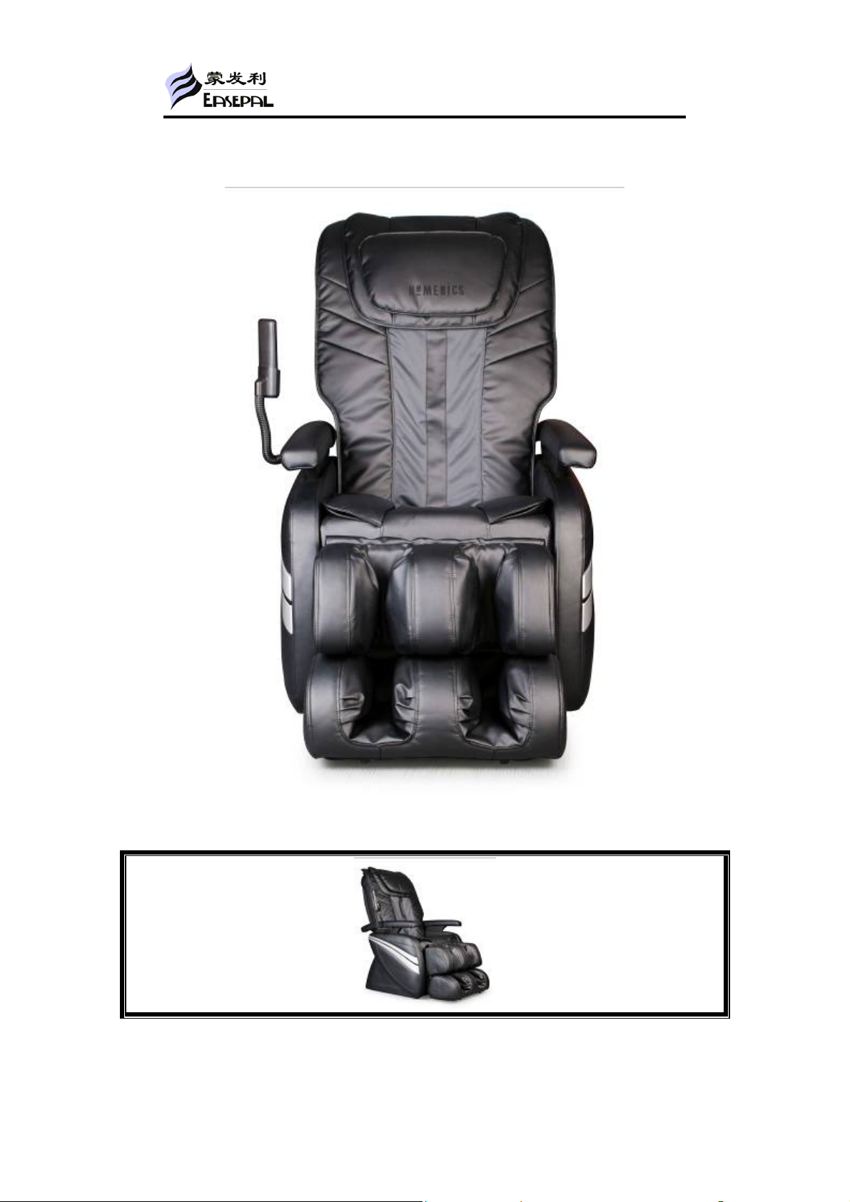
Table of Contents
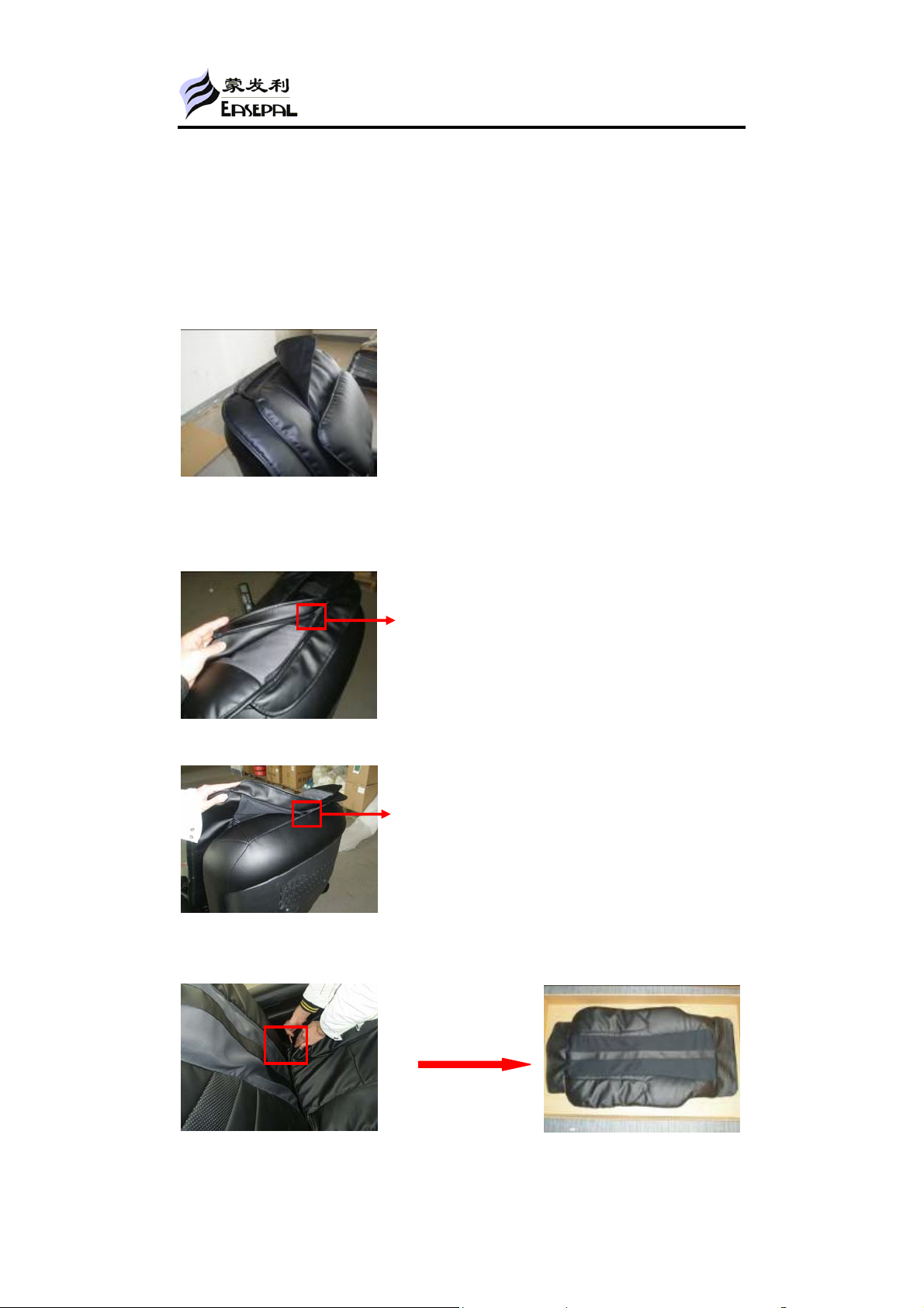
1:Maintenance of the small pillow, big pillow and backrest pad 。。。。。。。。。。。。。。。。。。。7
2:Disassembly of the fabric of the backrest。。。。。。。。。。。。。。。。。。。。。。。。。。。。。。。。。。。。。8
3:Disassembly of backrest。。。。。。。。。。。。。。。。。。。。。。。。。。。。。。。。
。。。。。。。。。。。。。。。。。。。8
4:Maintenance of the rear cover and the front cover of the backrest.。。。。。。。。。。。。。。。9
5:Disassembly of the Kneading motor 。。。。。。。。。。。。。。。。。。。。。。。。。。。。。。。。。。。。。。。。10
6:Disassembly of the massage mechanism.。。。。。。。。。。。。。。
。。。。。。。。。。。。。。。。。。。。。。。11
7:Disassembly of the up & down stroke photo-electricity。。。。。。。。。。。。。。。。。。。。。。。。。12
8:Disassembly of the Main PCB。。。。。。。。。。。。。。。。。。。。。。。。。。。。。。。。。。。。。。。。。。。。
。。13
9:Disassembly of the seat pad。。。。。。。。。。。。。。。。。。。。。。。。。。。。。。。。。。。。。。。。。。。。。。。。14
10:Disassembly of the remote controller。。。。。。。。。。。。。。。。。。。。。。。。。。。。。。。。。。。。。。。15
11:Disassembly of the inflator pump。。。。。。。。。。。。。。。。。。。。。。。。。。。。。。。。。。。。。。。。。。15
12:Disassembly of the air valves。。。。。。。。。。。。。。。。。。。。。。。。。。。。。。。。。。。。。。。。。。。。。。16
13:Disassembly of the transformer。。。。。
。。。。。。。。。。。。。。。。。。。。。。。。。。。。。。。。。。。。。。。17
14:Disassembly of the recline actuator。。。。。。。。。。。。。。。。。。。。。。。。。。。。。。。。。。。。。。。。。17
15:disassembly of the arm rest cover。。。。。。。。。。。。。
。。。。。。。。。。。。。。。。。。。。。。。。。。。。。18
16:Disassembly of the side cover (upper and lower)。。。。。。。。。。。。。。。。。。。。。。。。。。。。。。19
17:Disassembly of the foot rest cover。。。。。。。。。。。。。。。。。。。。。。。。。。。。。。。。。。
。。。。。。。。20
18: Disassembly of the air bag and the vibration motor of the foot rest。。。。。。。。。。。。。。。21