Eastwood QST 30 User manual

QST-30/60®
SCROLL COMPRESSOR
INSTRUCTIONS
Item #63600

2Eastwood Technical Assistance: 800.343.9353 >> tech@eastwood.com
The EASTWOOD ELITE QST 30/60®AIR COMPRESSOR has been engineered and developed using breakthrough Scroll Pump Technology. It operates at lower
sound and vibration levels while producing much greater air output with lower power demands than old technology, conventional piston-type air compressors.
The unique Scroll pump design also has far fewer moving parts and significantly reduced friction for greater reliability and longer life.
CONTENTS
(1) Eastwood Elite QST 30/60 Scroll Type Air Compressor
MOISTURE CATCH SYSTEM HARDWARE
(1) 500ml clear, oil and moisture resistant Bottle
(1) Lid Assembly (includes: Metal Outer Lid, Lid Liner, Gasket, Hardware)
(1) 90° Brass Barbed Fitting
(3) M5x0.80x20 Phillips Round Head Screws with Lock Washers, Washers and Nuts, (1) set installed in Lid Assembly
SPECIFICATIONS
Power Requirement: 208/240V, 60Hz, Single Phase
Full Load Amps: 17
Motor Horsepower: 4 hp
Tank Size: 26.4 gallon [100 liter]
Tank Fill Time: 3 minutes max.
Air Delivery: 12.7 SCFM @ 90 PSI
Cut-in Pressure: 115 PSI [7.9 bar]
Cut-out Pressure: 145 PSI [10 bar]
Max. Pressure: 145 PSI [10 bar]
Pressure Relief Valve Setting: 160 PSI [11 bar]
Motor and Scroll Pump RPM: 1750
Scroll Pump Oil Capacity (Oil Change): 60 ounces [1.77 liter]
Sound Reading, Running, @ 3.2 ft [1m]: 63 dB +/- 5%*
Power Cord: 6ft, 3-conductor grounded, 10 AWG
DANGER indicates a hazardous situation which, if not avoided, will result in death or serious injury.
WARNING indicates a hazardous situation which, if not avoided, could result in death or serious injury.
CAUTION indicates a hazardous situation which, if not avoided, could result in minor or moderate injury.
NOTICE is used to address practices not related to personal injury.
SAFETY INFORMATION
The following explanations are displayed in this manual, on the labeling, and on all other information provided with this product:

To order parts and supplies: 800.343.9353 >> eastwood.com 3
READ INSTRUCTIONS
• Thoroughly read and understand these product instructions before using the Compressor.
• Keep these product instructions for future reference.
FIRE OR EXPLOSION HAZARD!
• Never spray flammable liquids in a confined area. It is normal for the motor and pressure switch to produce sparks while operating.
If sparks come into contact with vapors from gasoline or other solvents, they may ignite, causing fire or explosion. Always operate
the compressor in a well-ventilated area. Do not smoke while spraying. Do not spray where sparks or flame are present.
Keep compressor a minimum of 20 feet from spray area.
FIRE HAZARD!
• Never allow the compressor to operate unattended. Always move power switch to the “OFF” position before leaving the work area.
ELECTRICAL SHOCK HAZARD!
• Never use an electric air compressor outdoors when it is raining or on a wet surface, as it may cause an electric shock.
• Compressor must be installed by a licensed electrician.
INJURY HAZARD!
• This unit starts automatically. ALWAYS shut the compressor off at the pressure switch, bleed all pressure from the tank, then shut off
breaker or disconnect power supply before servicing the compressor, and when the compressor is not in use.
• Never direct high-pressure airstream to exposed flesh.
• This compressor must be located only on a flat, level and secure surface. Do not locate the compressor on an elevated platform,
table, bench, roof or other non-secure location.
• Before performing any service, turn Power Switch to the “OFF” position, shut off breaker or disconnect power supply and release
pressure from Tank until Gauge indicates 0 PSI.
• The Oil Tank may be under pressure. Opening the Drain Valve or removing the Fill Plug under pressure can cause oil to be blown out
at high velocity. Move Power Switch to the “OFF” position. Release pressure from the Tank until Tank Pressure Gauge indicates 0 PSI.
Disconnect Compressor from power supply. Always wear appropriate eye protection.
BURN HAZARD!
• COMPONENTS ARE HOT! Significant heat is generated during operation. Allow to cool a minimum of 1 hour after last use before
servicing to avoid burns.
EYE INJURY HAZARD!
• Air, moisture and debris can be ejected at high velocity while using this equipment. Always wear ANSI Z87 approved eye protection
when operating this compressor and associated equipment.
HEALTH HAZARD!
• Air discharged from this compressor is not intended for and should never be used as supply air for human consumption.
SAFETY INFORMATION

4Eastwood Technical Assistance: 800.343.9353 >> tech@eastwood.com
BURST HAZARD!
• Check the manufacturer’s maximum pressure rating for air tools and accessories. Compressor outlet pressure must be regulated to
never exceed the maximum pressure rating of the tool. Relieve all pressure through the hose before attaching or removing accessories.
• Do not weld, drill or modify the air tank of this compressor. Welding or modifications on the air compressor tank can severely impair
tank strength and cause an extremely hazardous condition.
• Do not adjust the Pressure Relief Valve for any reason. The Pressure Relief Valve has been pre-set at the factory for the maximum
safe pressure of this unit. Personal injury and/or property damage may result if the relief valve is tampered with.
• Use only hose, pipe and fittings rated for compressed air distribution lines. Do not use plastic or PVC pipes.
• Verify the oil drain valve is completely closed before operation. Failure to close the oil drain valve may result in pressure causing the
moisture drain system to burst.
• To provide proper ventilation for cooling and prevent overheating, the compressor must be kept a minimum of 12 inches (31 cm)
from the nearest wall, in a well–ventilated area.
• The Eastwood Elite QST 30/60 Compressor is mounted on Casters and can vibrate or move slightly during operation.
Always lock Casters before running.
• Fluids drained from the Moisture Drain Bottle are hazardous materials and should be disposed of in compliance with local regulations.
SAFETY INFORMATION

To order parts and supplies: 800.343.9353 >> eastwood.com 5
COMPRESSOR SET-UP
STEP 1 – CHECK OIL LEVEL
• Move Power Switch to the “OFF” position (FIG 1).
• Release pressure from the Tank until Tank Pressure Gauge indicates 0 PSI.
• Disconnect Compressor from power supply.
• Remove the Oil Fill Plug/Dipstick from the upper front area of the
Oil Reservoir (FIG 2).
NOTE: Do not lose the Oil Fill Plug/Dipstick Seal.
• Check oil level by observing the level on the Dipstick. The oil level is
acceptable when it is BETWEEN the top mark and bottom mark
(FIG 3). If necessary, carefully add or remove oil until the level is
BETWEEN the marks.
• Check for full closure of the Drain Valve located on the Oil Reservoir (FIG 4).
• If needed, add #31718 Eastwood Synthetic Scroll Compressor Oil to the fill
port of the Oil Reservoir using a suitable funnel (FIG 5).
• Check the condition of the Seal then replace Oil Fill Plug/Dipstick and
tighten securely.
Before starting and running the Eastwood Elite QST 30/60,
the following brief steps MUST be performed:
• Place the Compressor on a level surface.
Oil is extremely critical to the operation and performance
of the Compressor. The oil must first be checked before any
other steps are taken.
FIG. 1FIG. 1
FIG. 3FIG. 3
FIG. 5FIG. 5
FIG. 4FIG. 4
FIG. 2FIG. 2
INJURY HAZARD!
The Oil Tank may be under pressure. Opening the Drain Valve
or removing the Fill Plug under pressure can cause oil to be
blown out at high velocity. Move Power Switch to the “OFF”
position. Release pressure from the Tank until Tank Pressure
Gauge indicates 0 PSI. Disconnect Compressor from power
supply. Always wear appropriate eye protection.
Acceptable
Add Remove

6Eastwood Technical Assistance: 800.343.9353 >> tech@eastwood.com
FIG. 6FIG. 6
FIG. 7FIG. 7
FIG. 8FIG. 8
STEP 2 – CHECK AIR FILTER
• Remove the Lid from the Air Filter Housing by rotating the Lid counter-
clockwise to unlock it (FIG 6).
• Check that the Paper Element is in place (FIG 7), then replace the Air Filter
Lid. Note that the snorkel of the Air Cleaner Housing must be pointing
downward (FIG 8).
STEP 3 – ELECTRICAL CONNECTION
• For best performance, the Compressor must be installed on a dedicated cir-
cuit, with a circuit breaker or fuse for protection. Each time the Compressor
motor starts, it will momentarily draw several times its full load amperage. It
is important to consider this start-up surge when specifying circuit breakers
or fuses. If fuses are used, time-delay type must be installed.
• The power supply wiring must be adequately sized to prevent dangerous
overheating and low voltage at the Compressor during startup and running.
Low voltage will cause difficult starting, overheating, and excessive tripping
of circuit breakers. The wire gauge must be increased for longer wire runs
to accommodate the increased resistance inherent in longer runs. Refer to
the National Electric Code to determine the proper wire gauge for your wire
run length. Low voltage can also be caused by low supply voltage from the
power company, or from other equipment running on the same line.
• For safety reasons, install a disconnect switch in the line from the electrical
panel to the Compressor as close to the Compressor as possible. When
the switch is off, all power to the Compressor is disconnected. When the
switch is on, the compressor will start and stop automatically as it will be
controlled by the pressure switch.
LockedLocked
UnlockUnlock
Refer to the Compressor nameplate for voltage and amper-
age requirements. All wiring must be done by a licensed
electrician, in accordance with National Electric Code and
state and local requirements.

To order parts and supplies: 800.343.9353 >> eastwood.com 7
STEP 4 – MOISTURE DRAIN SYSTEM
The Moisture Drain System is specifically designed to provide enhanced moisture
extraction capability for operation in high humidity and extreme use environments.
Installation
• Use two M5 Phillips Head screws, Lock Washer, Washer and Nuts to secure
the Lid Assembly to the pre-installed Mounting Bracket (FIG 9).
• Screw the Bottle into the Lid.
• Install the 90° Brass Barbed Fitting to the Lid by threading it into the tapped
hole in the center of the Lid (FIG 10).
• Slip the oil drain hose over the Brass Barbed Fitting on the Moisture Drain
Lid, attaching it securely (FIG 11).
FIG. 9FIG. 9
FIG. 10FIG. 10
FIG . 11FIG . 11
FIG. 12FIG. 12
BURN HAZARD!
The Scroll Pump generates heat during operation.
Use caution when servicing to avoid burns.
If any air or oil leaks are discovered, call Eastwood Tech
at: 1-800-343-9353 or email at tech@eastwood.com
INJURY HAZARD!
Before performing any service, turn Power Switch
to the “OFF” position (FIG 1). Shut off breaker or discon-
nect power supply. Release pressure from Tank (FIG 12)
until Gauge indicates 0 PSI. and allow to cool minimum
1 hour after last use before servicing to avoid burns.
CAUTION! Open Slowly!
Open
Close
STEP 5 – CHECK RUN PROCEDURE
• Close all outlet valves.
• Connect Compressor to power supply.
• Move the Power Switch to the “ON” position (FIG 1).
• Allow the Compressor to run until it builds full pressure and
automatically shuts off (approx. 3 minutes)
• Move the Power Switch to the “OFF” position.
• Listen for any air leakage and observe the Scroll case, all lines and
fittings for any evidence of oil leakage.
• If no leaks exist, the Eastwood Elite QST 30/60 Compressor is now
ready for use.

8Eastwood Technical Assistance: 800.343.9353 >> tech@eastwood.com
COMPRESSOR OPERATION
• Close the Water Drain Valve located at the underside of the Tank (FIG 12).
• Move the Power Switch to the “ON” position (FIG 1).
• Allow the Tank pressure to build to 145 PSI [10 bar] before each use. With the Air Compressor turned on, operation is automatic and under the control of
the internal Pressure Controller. It will turn off @ 145 PSI [10 bar] and automatically restart @ 115 PSI [7.9 bar].
The Eastwood Elite QST 30/60 Compressor is designed with a high efficiency, 1/2” Ball Valve at the air outlet with 1/2” FNPT
threads. It is strongly recommended to use 1/2” or larger air lines and fittings throughout your system. The use of 3/8” or smaller
lines is acceptable but will greatly hamper performance.
AIR LINE CONNECTION
It is strongly advisable to use a suitable high efficiency Air Regulator and Moisture/Oil Separator in a well-planned air-line layout after the Air Outlet Valve.
COMPRESSOR LOCATION
POSITIONING
• Locate all sides of the Compressor no less than 1 foot [0.3m] away
from any wall or closure.
• Maintain at least 2 feet [0.6m] of free space above the unit.
• Locate in a clean dry area away from other equipment which may
produce excessive heat or moisture.
• It is important to keep dust and debris from restricting air flow
through the compressor oil cooler. Do not operate compressor in a
small, enclosed area or under a cover.
CASTER LOCKING
To Lock:
• Note that both of the Swivel Casters are equipped with brakes.
Push down on the Paddles to lock brakes (FIG 13). Lift up on the
paddles to release brakes.
FIG. 13FIG. 13
Lock
Unlock
The Eastwood Elite QST 30/60 Compressor is mounted
on Casters and can vibrate or move slightly during
operation. Always lock Casters before running.
The Eastwood Elite QST 30/60 Compressor gener-
ates heat during operation. Sufficient space must be
provided around the unit for cooling air circulation.
Unplug/disconnect from electrical power when not in use.

To order parts and supplies: 800.343.9353 >> eastwood.com 9
AIR TANK CONDENSATION DRAIN
In normal use, particularly in humid environments, moisture will condense and collect in the tank. It must be drained daily to prevent internal tank corrosion
and ultimate failure.
Tank moisture draining procedure:
• Move the Power Switch to the “OFF” position.
• Release pressure from the Tank until the Tank Pressure Gauge indicates 0 PSI.
• Place a suitable container under the Drain Valve.
• Slowly open the Drain Valve located on the underside of the Tank (FIG 12).
• Close Drain Valve securely when finished.
Condensate is a polluting material and should be disposed of in compliance with local regulations.
If drain valve becomes clogged, release all air pressure, remove and clean valve, then reinstall.
Opening the Drain Valve before releasing pressure from the Tank will cause contaminated water to be blown out at high velocity.
Release pressure from the Tank until Tank Pressure Gauge indicates 0 PSI. Always wear appropriate eye protection.
OIL TANK CONDENSATION DRAIN
Operation
• The Moisture Drain System is designed to provide a means to easily drain excess moisture (water) which builds up in the oil tank. Check for moisture
monthly using the following procedure.
NOTE: For heavy use in high humidity conditions, it is recommended to drain the oil tank condensation weekly.
• Move Power Switch to the “OFF” position.
• Release pressure from Tank until Tank Pressure Gauge indicates 0 PSI.
• Disconnect Compressor from power supply.
• Allow the unit to sit at least 8 hours without operating. This allows the water sufficient time to settle to the bottom of the oil tank for easy removal.
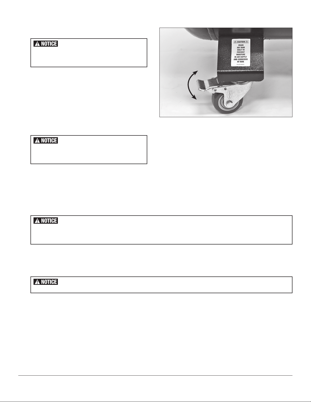
• Verify the Oil Drain Hose is connected to the Moisture Drain Bottle.
• Slowly open the Oil Drain Valve and allow any clear liquid (water) to drain.
• As soon as you observe the honey-colored oil coming out, close the drain valve.
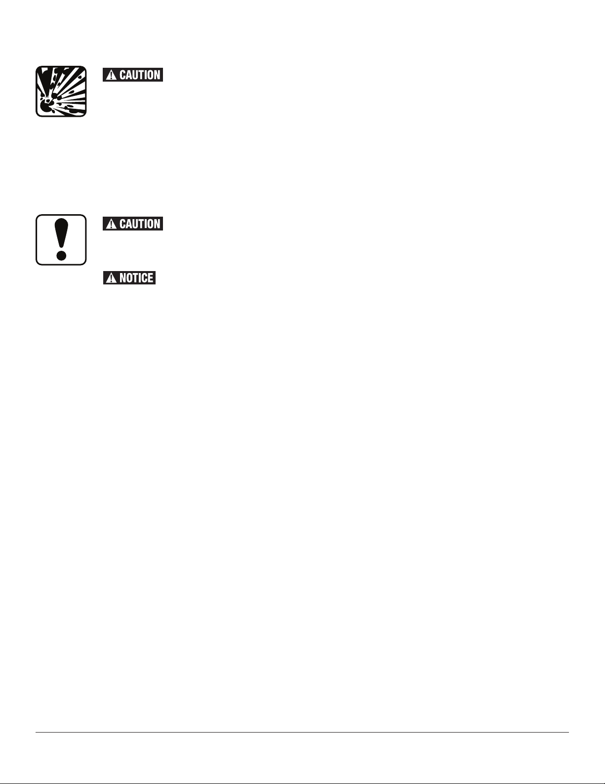
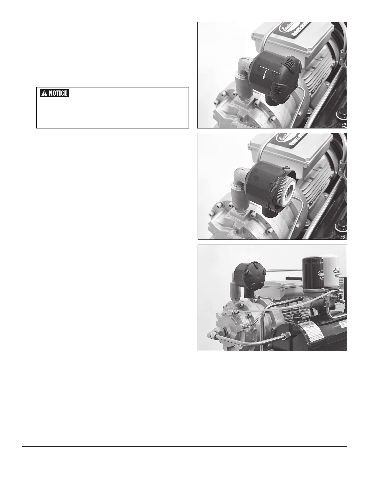
• Verify the oil level is still acceptable. Remove the Oil Fill Plug/Dipstick from the upper front area of the Oil Reservoir (FIG 2).
• Check oil level by observing the level on the Dipstick. The oil level is acceptable when it is BETWEEN the top mark and bottom mark (FIG 3).
• If necessary, carefully add or remove oil until the level is BETWEEN the marks.
• Inspect the Oil Fill Plug/Dipstick Seal and replace the Oil Fill Plug/Dipstick and tighten securely.
• Check for full closure of the Drain Valve located on the Oil Reservoir (FIG 4).
• The compressor may be started and operated as normal.
Maintenance
• Remove and drain the Bottle when the moisture level approaches 1/2 full.
• Wash Bottle completely with soap and hot water. Dry thoroughly.
Fluids drained from the Moisture Drain Bottle are hazardous materials and should be disposed of in compliance with local regulations.
INJURY HAZARD!
Before performing any service, turn Power Switch to the “OFF” position (FIG 1). Shut off breaker or disconnect power supply. Release
pressure from Tank until Gauge indicates 0 PSI.

10 Eastwood Technical Assistance: 800.343.9353 >> tech@eastwood.com
MAINTENANCE
MONTHLY:
Drain moisture from Oil Tank and Air Tank. For instruction see OIL TANK CONDENSATION DRAIN and AIR TANK CONDENSATION DRAIN.
YEARLY:
Perform oil change, Oil Filter replacement, Moisture Separator replacement, and Air Filter replacement.
NOTE: For heavy use in high humidity conditions, it is recommended to drain the oil tank condensation weekly.
If operating in excessively dusty or dirty environments, vacuum debris or dust from the oil cooler fins and periodically follow the AIR FILTER CHANGE procedure
to remove, blow-out and re-install Air Filter Element.
OIL CHANGE ONLY
• Move Power Switch to the “OFF” position (FIG 1). Release pressure from Tank until Tank Pressure Gauge indicates 0 PSI.
• Disconnect Compressor from power supply.
• Remove the drain hose from the Moisture Drain System Barbed Fitting and securely position it above a suitable drain pan, then slowly open the
Oil Drain Valve (FIG 4).
TIP: It is advisable to place spacers under the opposite side Casters lifting the Compressor slightly on that end to force the maximum amount of oil
to drain from the Reservoir into a suitable container (FIG 14).
BURN HAZARD!
Significant heat is generated during operation. Components and oil may be hot. Allow to cool a minimum of 1 hour after last use
before servicing to avoid burns.
INJURY HAZARD!
Before performing any service, turn Power Switch to the “OFF” position
(FIG 1)
. Shut off breaker or disconnect power supply.
Release pressure from Tank until Gauge indicates 0 PSI.
INJURY HAZARD!
The Oil Tank may be under pressure. Opening the Oil Drain Valve or removing the Fill Plug under pressure can cause oil to be blown out at
high velocity. Move Power Switch to the “OFF” position, release pressure from the Tank until Tank Pressure Gauge indicates 0 PSI, and
disconnect Compressor from power supply before opening Drain Valve or removing Fill Plug. Always wear appropriate eye protection.
Used Oil is a polluting material and should be disposed of in compliance with local regulations.
• After the oil has drained, close the Oil Drain Valve completely then re-connect the drain hose to the Moisture Drain System Barbed Fitting.
• Remove the Oil Fill Plug/Dipstick from the upper front area of the Oil Reservoir (FIG 2).
NOTE: Do not lose the Oil Fill Plug/Dipstick seal.
• Add #31718 Eastwood Synthetic Scroll Compressor Oil to the fill port of the Oil Reservoir using a suitable funnel (FIG 5).
• With the Compressor sitting on a level surface, check oil level by observing the level on the Dipstick. The oil level is acceptable when it is between the
marks (FIG 3). If the oil level is below the bottom mark, oil must be added.
• Check the condition of the seal then replace Oil Fill Plug/Dipstick and tighten securely.

To order parts and supplies: 800.343.9353 >> eastwood.com 11
OIL AND FILTER CHANGE
Used Oil is a polluting material and should be disposed of
in compliance with local regulations.
BURN HAZARD!
Significant heat is generated during operation. Components and oil may be hot. Allow to cool a minimum of 1 hour after last use
before servicing to avoid burns.
INJURY HAZARD!
Before performing any service, turn Power Switch to the “OFF” position (FIG 1). Shut off breaker or disconnect power supply
and release pressure from Tank until Gauge indicates 0 PSI.
INJURY HAZARD!
The Oil Tank may be under pressure. Opening the Oil Drain Valve or removing the Fill Plug under pressure can cause oil to be blown out at
high velocity. Move Power Switch to the “OFF” position, release pressure from the Tank until Tank Pressure Gauge indicates 0 PSI, and
disconnect Compressor from power supply before opening the Drain Valve or removing Fill Plug. Always wear appropriate eye protection.
• Move Power Switch to the “OFF” position.
• Release pressure from Tank until Tank Pressure Gauge indicates 0 PSI.
• Disconnect Compressor from power supply.
• Remove the drain hose from the Moisture Drain System Barbed Fitting and
securely position it above a suitable drain pan, then slowly open the Drain
Valve. TIP: It is advisable to place spacers under the opposite side Casters
lifting the Compressor slightly on that end to force the maximum amount of
oil to drain from the Reservoir into a suitable container (FIG 14).
FIG. 14FIG. 14
• After the oil has drained, close the Oil Drain Valve completely then re-connect the drain hose to the Moisture Drain System Barbed Fitting.
• Remove the Oil Fill Plug/Dipstick from the upper front area of the Oil Reservoir (FIG 2).
NOTE: Do not lose the Oil Fill Plug/Dipstick seal.
• Add #31718 Eastwood Synthetic Scroll Compressor Oil to the fill port of the Oil Reservoir using a suitable funnel (FIG 5).
• With the Compressor sitting on a level surface, check oil level by observing the level on the Dipstick. The oil level is acceptable when it is between the
marks (FIG 3). If the oil level is below the bottom mark, oil must be added.
• Check the condition of the seal then replace Oil Fill Plug/Dipstick and tighten securely.
• Remove Oil Filter (Black Canister) from the Filter Manifold.
• Remove Moisture Separator (White Canister) from the Filter Manifold.
• Clean all gasket sealing surfaces thoroughly.
The Oil in this unit is under high pressure and filters MUST be tight to prevent leakage. To tighten: Snug down by hand then tighten
3/4 to 1 full turn after initial seal contact.

12 Eastwood Technical Assistance: 800.343.9353 >> tech@eastwood.com
AIR FILTER CHANGE
• Remove the Lid from the Air Filter Housing by rotating the Lid counterclockwise to unlock it (FIG 6).
• Remove the Air Filter Element and discard it.
• Replace the Air Filter Element with a new Eastwood #31717 and re-install the Air Filter Housing Lid. Note that the peg of the Air Cleaner Cover must
be indexed with one of the 5 recesses around the circumference of the Filter Housing and the snorkel of the Air Cleaner Housing must be pointing
downward (FIG 8).
BURN HAZARD!
Components are Hot! Significant heat is generated during operation. Allow to cool a minimum of 1 hour after last use before
servicing to avoid burns.
INJURY HAZARD!
Before performing any service, turn Power Switch to the “OFF” position (FIG 1). Shut off breaker or disconnect power supply.
Oil Filter
#31715
Moisture Separator
#31716
✓
✓
FIG. 15FIG. 15
Used Oil is a polluting material and should be disposed of in
compliance with local regulations.
If any air or oil leaks are discovered, call Eastwood Tech
at: 1-800-343-9353.
• Install a new Eastwood #31715 Oil Filter (Black Canister) at the left position
of the Filter Manifold (FIG 15).
• Install a new Eastwood #31716 Moisture Separator (White Canister) at the
right position of the Filter Manifold (FIG 15).
• With the Oil Drain and Air Tank Drain Valves closed, turn the Power Switch
back to “ON”, allow full pressure to build until the Pressure Switch auto-
matically shuts the unit off then turn the Power Switch to “OFF”.
• Listen for any air leakage and observe the Scroll case, all lines and fittings
for any evidence of oil leakage.

To order parts and supplies: 800.343.9353 >> eastwood.com 13
TROUBLESHOOTING
PROBLEM CAUSE CORRECTION
Oil/Water Mist
Spraying from
Under Pres-
sure Switch
The unit is collecting excess water in
the moisture filter #31716 and oil tank
which is raising oil level and resulting in
oil/water being forced into the white ny-
lon discharge hose going to the unloader
valve under the pressure switch.
Refer to OIL TANK CONDENSATION DRAIN for preventing condensation build up
by draining it regularly.
Unit Does Not
Turn On or Run
No power to unit or defective pressure
switch.
Check breaker is not tripped. If breaker is Ok – disconnect unit from power.
Check Continuity across switch terminals. A good switch will show continuity
across both sets of terminals, if one set of terminals is OPEN switch is bad.
Replace pressure switch #32207.
Motor Runs
Slow or Hard
to Start
Improper Supply Voltage/Circuit. Assure unit has actual 208/240 on min 30-amp circuit and not 120VAC.
Defective start and/or run capacitor.
Disconnect unit from power.
• Remove Motor Electric Box Cover (on top of motor).
• Look at both capacitors for leaking oil, black soot, bloated or cracked cases.
• If defective- replace capacitors and motor controller.
Replace Start Capacitor #32213.
Replace Run Capacitor #32214.
Replace Motor Controller #32215.
Air Discharges
From Under
Pressure
Switch When
Unit Shuts Off
at 145 PSI
The Unloader Valve is located below the
Pressure Switch and is in place to relive
air pressure from the Scroll Pump and
Oil Tank. This discharge will last up to
20 seconds and is necessary to relive
air pressure in the Pump before next
cycle starts to eliminate starting against
a head pressure.
This is normal operation.
Overpressure
Relief Valve
Opens. Unit
Will Not Shut
Off.
Pressure Switch is stuck in “ON”
position- unit will continue to run even
if pressure switch knob is turned to
“OFF”. Unit will continue to vent through
Overpressure Relief Valve.
Replace Pressure switch #32207.
Motor Makes
Loud Metallic
Grinding Noise
Motor is defective from either bearing
failure, oil starvation or overheating.
Replace the following item:
Motor/Pump assembly #32208.
Squeaking/
Chatter Noise
at Air Filter
When Unit
Starts
Aluminum cylinder below air filter hous-
ing is the Intake Check valve. The valve
seal is making the noise.
It will not harm or hinder performance of unit and will cease after a few cycles.

14 Eastwood Technical Assistance: 800.343.9353 >> tech@eastwood.com
TROUBLESHOOTING
PROBLEM CAUSE CORRECTION
Unit is Leaking
Oil at Fitting(s) Loose Fitting. Tightening fitting resolves most issues.
Rust in Water
When Draining
Tank
Compressors are designed to accumu-
late moisture in the air tank instead of in
your air stream.
We recommend draining air tank weekly to remove moisture. It is not uncom-
mon to have brown/rust colored water in tank as the inside of the tank is bare
steel to eliminate any coating delamination. This will ultimately disappear as a
film of oil will coat inside of tank during use (see page 9).
Unit Will Not
Reach 145 PSI,
Shuts Off Early
Defective Pressure gauge. Replace pressure gauge with known good gauge and retest unit. If gauge is
accurate replace Pressure Switch #32207.
Defective Pressure Switch
(On/Off switch). Replace Pressure Switch #32207.
Sludge in Oil
Tank and On
Dipstick
Light, intermittent use, operation
in warm, damp locations, or during
high humidity weather conditions will
contribute to the formation of excess
condensation in the system.
Drain and replace oil with 2 qts #31718 Eastwood Scroll Compressor Oil.
Replace Oil Filter #31715.
Replace Moisture Filter #31716.
See Monthly Maintenance Guide regarding Moisture Draining of oil tank.

To order parts and supplies: 800.343.9353 >> eastwood.com 15
NOTES

ADDITIONAL ITEMS
R&D MUST-HAVE ACCESSORIES
© Copyright 2022 Eastwood Automotive Group LLC 5/22 Instruction item #63600Q Rev 1
If you have any questions about the use of this product, please contact
The Eastwood Technical Assistance Service Department: 800.343.9353 >> email: tech@eastwood.com
PDF version of this manual is available at eastwood.com
The Eastwood Company 263 Shoemaker Road, Pottstown, PA 19464, USA
800.343.9353 eastwood.com
MAINTENANCE & REPAIR PARTS
#31715 Replacement Eastwood Oil Filter
#31716 Replacement Eastwood Moisture Separator
#31718 Eastwood Synthetic Scroll Compressor Oil (1 Quart [0.946 liter])
#32207 Replacement Pressure Cut-off Switch
#32213 Replacement Start Capacitor
#32214 Replacement Run Capacitor
#32215 Replacement Motor Controller
#32108 Replacement Motor Assembly
#33075 Replacement Pressure Safety Release Valve
#32201 Replacement Pressure Gauge
#32205 Replacement Air Filter Housing
#31717 Replacement Air Filter Element
#32209 Replacement Dipstick Seal
#31722 Replacement 24” Nylon Hose Kit
Visit eastwood.com for complete info and pricing.
#32499
Hose Reel
#31633
Complete Filtration System
#31632
Blow Gun
Other manuals for QST 30
1
This manual suits for next models
2
Table of contents
Other Eastwood Air Compressor manuals