Eastwood QST-80 User manual

QST-80/120
SCROLL COMPRESSOR
INSTRUCTIONS
Item #32500

2Eastwood Technical Assistance: 800.343.9353 >> tech@eastwood.com
The EASTWOOD ELITE QST-80/120 SCROLL COMPRESSOR has been engineered and developed using breakthrough Scroll Pump technology. It operates at
much lower sound and vibration levels while producing much greater air output with lower power demands than conventional piston-type air compressors.
The unique Scroll Pump design also has fewer moving parts and significantly reduced friction for greater reliability and longer life.
CONTENTS
(1) QST-80/120 Scroll Compressor
(1) 3/4” x 3-3/8” Pipe Nipple
(1) Side Panel Key
(1) Eastwood Instruction Manual
SPECIFICATIONS
Power Requirement: 208-240V, 60Hz, 31.0-amp, 3 phase
Motor Horsepower: 11 hp
Motor RPM: 3516
Sound Reading @ 10 ft. [3m]: 62 +/- 3 db.*
Air Output: 31.8 SCFM @ 90 PSI [900 l/min. @ 6.2 bar]
Cut-in Pressure: 115 PSI [8 bar]
Cut-out Pressure: 145 PSI [10 bar]
Max. Pressure: 145 PSI [10 bar]
Pressure Relief Valve Setting: 160 PSI [11 bar]
Oil Capacity:
Total System: 135 oz. [4.0 liter]
Oil Change (see maintenance schedule): 74 oz. [2.2 liter]
*Using standard sound level testing conditions. Results may vary based on compressor location and environment.

To order parts and supplies: 800.343.9353 >> eastwood.com 3
READ INSTRUCTIONS
• Thoroughly read and understand these product instructions before using the Compressor.
• Keep these product instructions for future reference.
FIRE OR EXPLOSION HAZARD!
• Never spray flammable liquids in a confined area. It is normal for the motor and pressure switch to produce sparks while operating.
If sparks come into contact with vapors from gasoline or other solvents, they may ignite, causing fire or explosion. Always operate
the compressor in a well–ventilated area. Do not smoke while spraying. Do not spray where sparks or flame are present.
Keep compressor a minimum of 20 feet from spray area.
FIRE HAZARD!
• Never allow the compressor to operate unattended. Always disconnect compressor from the electrical power supply before leaving
it unattended.
ELECTRICAL SHOCK HAZARD!
• Connect only to a 208-240VAC, 60Hz, 3 phase, 30 Amp circuit meeting all applicable local electrical codes.
INJURY HAZARD!
• This unit starts automatically. ALWAYS shut off the compressor, disconnect electrical power, and bleed all pressure from the tank
before servicing the compressor, and when the compressor is not in use.
• Do not use the unit with the Cover removed. Serious injury could occur from contact with moving parts.
• Never direct high-pressure airstream to exposed flesh.
• This compressor must be located only on a flat, level and secure surface. Do not locate the compressor on an elevated platform,
table, bench, roof or other non-secure location.
EYE INJURY HAZARD!
• Always wear ANSI Z87 approved eye protection when operating this compressor and associated equipment. Air, moisture and debris
can be ejected at high velocity while using this equipment.
HEALTH HAZARD!
• Air discharged from this compressor is not intended for and should never be used as supply air for human consumption.
INJURY HAZARD!
• Fan Blade can start at any time. To help avoid personal injury, keep hands clear.
DANGER indicates a hazardous situation which, if not avoided, will result in death or serious injury.
WARNING indicates a hazardous situation which, if not avoided, could result in death or serious injury.
CAUTION used with the safety alert symbol, indicates a hazardous situation which, if not avoided, could result in minor or moderate injury.
NOTICE is used to address practices not related to personal injury.
SAFETY INFORMATION
The following explanations are displayed in this manual, on the labeling, and on all other information provided with this product:

4Eastwood Technical Assistance: 800.343.9353 >> tech@eastwood.com
BURN HAZARD!
• The Scroll Pump generates heat during operation. Use caution when servicing to avoid burns.
BURST HAZARD!
• Check the manufacturer’s maximum pressure rating for air tools and accessories. Compressor outlet pressure must be regulated to
never exceed the maximum pressure rating of the tool. Relieve all pressure through the hose before attaching or removing accessories.
• DO NOT adjust the Pressure Relief Valve for any reason. The Pressure Relief Valve has been pre-set at the factory for the maximum
safe pressure of this unit. Personal injury and/or property damage may result if the relief valve is tampered with.
• Use only hose, pipe and fittings rated for compressed air distribution lines. Do Not use plastic or PVC pipes.
• Drain the moisture from the tank daily. An empty, dry tank will help prevent corrosion and prolong tank life.
• To provide proper ventilation for cooling and prevent overheating, the compressor must be kept a minimum of 3’ (31 cm) from the near-
est wall, in a well–ventilated area. DO NOT allow the Cover ventilation holes to be blocked or possible permanent damage could occur.
• REQUIRES 208-240 VAC, 60Hz., 3 phase.
COMPRESSOR SITE LOCATION
• The Eastwood Elite QST-80/120 Scroll Compressor must be located in an indoor area, on a firm, clean, level surface. A solid, level concrete floor is best.
• Select an area with adequate ventilation and air circulation. A minimum of 3’ [90 cm] of free space must be maintained around all sides and above the
compressor. This is to allow for adequate ventilation and panel removal and to allow room for access for maintenance purposes. Do not store objects
behind, alongside or on top of the compressor.
• Do not place the Scroll Compressor in an area where dust and debris can be drawn into the cooling vents and air intake or severe damage to the unit
can occur.
• The temperature environment for proper operation must be between 32°F and 110°F [0°C and 43°C]. The Compressor is equipped with over temperature
shut off circuitry which may activate in excessive ambient temperature conditions.
• For best performance, humidity levels should be below 75%. For extended operation in higher humidity environments, particular attention should be
devoted to draining tank of moisture.
FIRE OR EXPLOSION HAZARD!
Keep compressor a minimum of 20 feet from flammable or explosive vapors and materials.
The Scroll Compressor generates heat during operation and has a highly efficient heat-exchanging and air-cooled system.
Sufficient space must be provided around the unit for cooling air circulation.

To order parts and supplies: 800.343.9353 >> eastwood.com 5
COMPRESSOR SET-UP
• Level Scroll Compressor - Using an accurate level, check to see that
the Scroll Compressor is level and not prone to rocking or vibration.
Use suitable shims under the corners of the frame, if necessary, to achieve
a level condition.
• Remove Panels - Access to all interior components is by panel removal.
All four sides and top panels are removable:
- Front rear and side panels are removed by placing the included
triangular profile key over the triangular posts of the latches (FIG 1).
Front and rear panels have 2 latches each and are released by turning
the key 1/4 of a turn to the respective outside corner. End panels have
one latch each and are released with 1/4 turn to the right.
- After latch release, lift panel off locating pins on the outer floor of the
unit then pull up and away (FIG 2).
- The top panel is removed by inserting a 5mm hex key into the holes at
the corners and loosening the socket head cap screws.
NOTE: Do not remove the screws as the underside flange of the top
panel has “Keyhole” slots. Standing at the rear of the Compressor, slide
the top panel to the right to clear screw heads and lift off (FIGS 3 & 4).
FIG. 1
FIG. 2
FIG. 3
FIG. 4
Rotate 90° Rotate 90°
Out
Up
5mm
Loosen
✓
✓
✓
✓
✓
Slide Lift

6Eastwood Technical Assistance: 800.343.9353 >> tech@eastwood.com
• Check Oil Level – The Scroll Compressor is shipped with the correct
amount of Scroll Compressor Oil, however the oil level should be verified
as it is extremely critical to the function of the Scroll.
- View the Sight Gauge on the side of the Oil Reservoir to make sure
that it reads FULL (at or above the “M” line but not above the
“H” line (FIG 5).
- If the oil level is below the “M” line, oil must be added.
- If needed, remove the Fill Plug form the Oil Reservoir with a 22mm
wrench (not included) and add #31718 Eastwood Scroll Compressor Oil
to the fill port of the Oil Reservoir using a suitable funnel (FIG 6).
- Check the condition of the seal then replace Oil Fill Plug and tighten
securely.
• Check Air Filter – Clean, filtered intake air is vital to the life of the Scroll
as it is machined to extremely close tolerances.
- Check that the Cover on the Air Filter is latched correctly and hasn’t
vibrated loose in shipment. The two molded in arrows on the base and
lid should be aligned (FIG 7).
AIR LINE CONNECTION
To utilize the maximum performance from the Compressor, it is strongly recom-
mended to use 3/4” or larger air lines and fittings throughout your system.
The use of 3/8” or smaller lines and fittings will greatly hamper performance.
In order to protect valuable air tools and equipment and prevent contamina-
tion, it is strongly advisable to use a suitable, high efficiency Air Regulator
(not included) and Moisture/Oil Separator (not included) in a well-planned
air line layout.
If the oil level is found to be low, check all lines, fittings, oil
reservoir and heat exchanger for any signs of leakage from
shipping damage before continuing.
FIG. 5
FIG. 6
FIG. 7
The Eastwood Elite QST-80/120 Scroll Compressor is
designed to be used with a minimum external 60 Gallon
Air Tank and a 3/4” Flexible Air Line with 3/4” NPT input
and output threads.
H
M
L
Oil
Fill
✓
✓
✓
✓
✓
✓

To order parts and supplies: 800.343.9353 >> eastwood.com 7
ELECTRICAL CONNECTION
1. The 3 phase wiring connections are made at the Upper Terminals of the
Electrical Box (FIG 8).
2. The Scroll Compressor features a microprocessor in the control unit
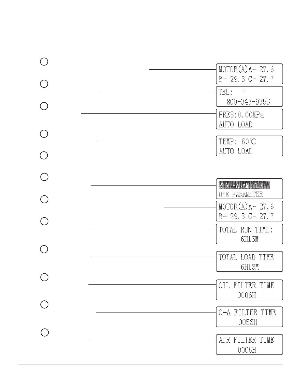
Control Panel Display which will detect incorrect phasing and will display
“ALARM1:” “PHASE REVERSE” and an audible alarm will sound.
3. If these conditions occur, it is an indication that the 3 Phase connections
have been done incorrectly. To correct, shut off power at main breaker
disconnect switch and revise the connection sequence of the three phase
upper terminals of the Electrical Box (FIG 11).
4. Press the SET Button to cancel alarm and reset the Error message in
the LCD Display window.
FIG. 8
The 3 phase wiring connections MUST be done in the proper
sequence or the motor could possibly run in reverse which
could cause severe and permanent damage to the Scroll.
✓
3 PHASE REQUIREMENTS
• 208-240V, 60Hz, 22-amp, 3 phase voltage and amperage requirements. All wiring must be done by a licensed electrician, in accordance with
National Electric Code and state and local requirements. For best performance, the Compressor must be installed on a dedicated circuit, with
circuit breaker or fuse protection. Each time the Compressor motor starts, it will momentarily draw several times its full load amperage.
It is important to consider this start-up surge when specifying circuit breakers or fuses. If fuses are used, time-delay type must be installed.
• The voltage variation between the rated input voltage requirements and that of the actual input voltage supply must not exceed +/- 10%.
If greater variation exists, a step-up or step down transformer must be installed.
• The voltage variation between legs of the 3-phase supply must be within 5%. If greater variation exists, a voltage regulator or rectifier must
be used.
• The power supply wiring must be adequately sized to prevent dangerous overheating and low voltage at the Compressor during startup and
running. Low voltage will cause difficult starting, overheating, and excessive tripping of circuit breakers. The wire gauge must be increased for
longer wire runs to accommodate the increased resistance inherent in longer runs. Refer to the National Electric Code to determine the proper
wire gauge for your wire run length. Low voltage can also be caused by low supply voltage from the power company, or from other equipment
running on the same line.
• For safety reasons, install a main breaker disconnect switch in the line from the electrical panel to the Compressor within momentary reach
of the Compressor. When the switch is off, all power to the Compressor is disconnected. When the switch is on, the compressor will start and
stop automatically as it will be controlled by the pressure switch.
S

8Eastwood Technical Assistance: 800.343.9353 >> tech@eastwood.com
FIG. 9
CONTROL PANEL FEATURES AND FUNCTIONS (FIG 9)
ASTART Button Turns Compressor On
BOFF Button Turns Compressor Off (Cooling Fan and Pressure Release Valve may still function)
CSET Button Enters Menu Selection / Alarm Reset
DDown Menu Button Scrolls Down in Menu Selections
EUp Menu Button Scrolls Up in Menu Selections
FSelection to Right Button Enables option selection / Moves cursor position right
GReturn Button Exit Menu Page or return to previous setting
HEmergency Stop Switch Stops all compressor functions in an emergency
JPower ON Indicator Illuminates GREEN when Start Button is ON
KRun Indicator Illuminates AMBER when Motor is running
LALARM Indicator Illuminates RED when a Fault Condition exists
S
▼
▲
▼
!
A
B
H
C D E F G
J
K
L

To order parts and supplies: 800.343.9353 >> eastwood.com 9
As an added precaution, the following check should be performed before starting the Compressor for the first time:
1. Obtain the assistance of an observer and view the Motor cooling fan blades visible through the screened housing at the end of the Motor case (FIG 10).
2. Have the same observer note the directional arrow label on the Motor case (FIG 10).
3. Depress the “START” Button of the Control Panel.
4. If the observer views the cooling fan begin to rotate in the opposite direction of the directional arrow label, depress the “OFF” Button immediately!
5. If 3 phase connection corrections are required, do so and repeat check sequence beginning at step 1.
6. If correct rotation of the Motor has been verified, proceed to COMPRESSOR OPERATION.
FIG. 10 FIG . 11
COMPRESSOR OPERATION
• Depress the “START” Button of the Control Panel (FIG 9).
• Allow the Tank pressure to build to 145 PSI [10 bar] before each use. With the Air Compressor turned on, operation is automatic and under the control of
the internal Pressure Controller. It will turn off @ 145 PSI [10 bar] and automatically restart @ 115 PSI [8 bar].
The Pressure Gauge is visible through the upper right-side Compressor Panel and indicates the actual output line and tank pressure.
When the pressure reaches the 145 PSI [10 bar] cutoff point, an Unloader Valve will automatically release static pressure in the
Scroll to allow it to easily restart without needing to overcome residual pressure. This produces a momentary audible “hiss” or
“burbling” sound and is normal.
Indicator Arrow
Fan rotation
Ground
Black White Red
✓
✓
✓
✓

10 Eastwood Technical Assistance: 800.343.9353 >> tech@eastwood.com
MENU SELECTIONS
The Microprocessor offers many display parameters to monitor major compressor functions and maintenance data including cumulative run time recording.
Whenever any of the Control Panel keys are pressed, the Display Panel illumination feature will activate and, if not touched within 1 minute, will automatically go out.
TO BEGIN DISPLAY SEQUENCE:
• Press 1st time:
Displays: Motor amperage draw for each individual 3-phase leg (FIG 12)
• Press 2nd time:
Displays: Eastwood Tech Phone # (FIG 13)
• Press 1st time:
Displays: Air Pressure (FIG 14)
(Air pressure at Scroll output, may read higher than Gauge Pressure visible at the side of the unit)
• Press 2nd time:
Displays: Scroll Air Temperature (FIG 15)
• Press Again:
Toggles between Air Pressure and Air Temperature.
• Press
Displays: RUN PARAMETER (FIG 16)
• Press Again:
Displays: Returns to motor amperage draw for each individual 3-phase leg: (FIG 12)
• Press
Displays: TOTAL RUN TIME (FIG 17)
(Records total overall unit running time)
• Press
Displays: TOTAL LOAD TIME (FIG 18)
(Records actual Scroll/Motor running time under load)
• Press
Displays: OIL FILTER TIME (FIG 19)
(Cumulative time of oil filtration)
• Press
Displays: OIL/AIR FILTER TIME (FIG 20)
(Cumulative time of moisture/oil separator filter)
• Press
Displays: AIR FILTER TIME (FIG 21)
(Cumulative time of air filtration)
▼
▲
▼
▲
▼
▼
▼
▼
▼
▼
▼
▼
FIG. 12
FIG. 13
FIG. 14
FIG. 15
FIG. 16
FIG. 17
FIG. 18
FIG. 19
FIG. 20
FIG. 21
FIG. 12

To order parts and supplies: 800.343.9353 >> eastwood.com 11
• Press
Displays: LUBE TIME (FIG 22)
(Cumulative time of Scroll Oil use)
• Press
Displays: ALARM1 (FIG 23)
(Records occurrence of PHASE REVERSE)
• Press
Displays: ALARM2 (FIG 24)
(Records occurrence of HIGH LOAD PRESSURE)
• Press
Displays: ALARM3 (FIG 25)
(Records occurrence of UNLOADED HIGH PRESSURE)
• Press
Displays: ALARM4 (FIG 26)
(Records occurrence of HIGH FAN TEMPERATURE)
• Press
Displays: ALARM5 (FIG 27)
(Records occurrence of HIGH MOTOR TEMPERATURE)
• Press
Displays: PROD DATE (FIG 28)
(Build date of unit)
• Press
Displays: SERIAL# (FIG 29)
(Serial # of unit)
• Press
Displays: C-STATE RX:-TX: (FIG 30)
(This is a manufacturer-only check point setting used for calibration purposes)
Pressing beyond the RUN PARAMETERS display will reveal three additional Menus (USE PARAMETERS, FAC PARAMETERS and
MOD PARAMETERS). Pressing will produce a prompt in the Display Window that requests a Password be entered in order to
gain access. These menus are exclusively used at assembly to achieve initial factory settings and calibrations only. No password is
available and no user manipulation of these settings is possible.
▼
▼
▼
▼
▼
▼
▼
▼
▼
FIG. 22
FIG. 23
FIG. 25
FIG. 26
FIG. 24
FIG. 27
FIG. 28
FIG. 29
FIG. 30
▼
▼

12 Eastwood Technical Assistance: 800.343.9353 >> tech@eastwood.com
THERMAL OVERLOAD PROTECTION
As long as the air output capacity, 31.8 SCFM @ 90 PSI [900 l/min. @ 6.2 bar], of the Eastwood Elite QST-80/120 Scroll Compressor is not exceeded, it is ca-
pable of running continuous, automatically controlled on/off cycles. If the air output is exceeded, the Compressor will run continuously in efforts to meet demand.
If this occurs, the Motor and or Scroll will overheat. When the Compressed Air Outlet Temperature Sensor detects 203°F [95°C] the Thermal Overload alarm will
activate (audible warning buzzer and LCD Screen Warning display) however, the Motor will continue to run for a short period. At this point, all work demands of
the Compressor should be stopped immediately and the unit should be allowed to continue to run without a load until it cools. This will automatically cancel the
Thermal Overload LCD Screen Warning, however, the audible warning buzzer alarm must be reset by pressing the Button (FIG 9).
If the Thermal Overload warning in not heeded, the Motor will shut off when the Compressed Air Outlet Temperature Sensor detects 212°F [100°C]. The cooling
fan will continue to run. The motor will not start until it has cooled sufficiently.
OIL TEMPERATURE ALARM
In addition to the Motor and Scroll overheating protection, the Oil Over Temperature sensor constantly monitors the Scroll oil temperature. If the oil temperature
becomes excessive, the Oil Over Temperature alarm will activate (audible warning buzzer and LCD Screen Warning display) however, the Motor will continue to
run for a short period. At this point, all work demands of the Compressor should be stopped immediately and the Compressor housing should be checked for
blockage of cooling air side vent panels, or blockage of the Fan Air Outlet on top.
The Fan should be allowed to continue to run until the oil sufficiently cools. This will automatically cancel the Oil Over Temperature LCD Screen Warning however,
the audible warning buzzer alarm must be reset by pressing the Button (FIG 9).
If the Oil Over Temperature warning is not heeded, the Motor will shut off and will will not start until the oil has cooled sufficiently.
LOW OIL LEVEL ALARM
In addition to the Motor and Scroll overheating protection, the Oil Level sensor constantly monitors the Scroll oil level. If the oil level becomes too low, the
Low Oil Level alarm will activate (audible warning buzzer and LCD Screen Warning display) and the Motor will stop running.
The oil level must be checked and filled with the necessary amount of Eastwood Scroll Compressor Oil and the alarm must be reset by pressing the
Button (FIG 9).
The Scroll, Oil/Moisture Tank, and all lines should be checked for leaks to determine the reason for the low oil condition before resuming use.
PRESSURE RELIEF VALVE
The Pressure Relief Valve (FIG 31) is factory set to release at 160 PSI
[11 bar]. DO NOT attempt to adjust or tamper with it. Doing so can cause
an unsafe condition resulting in violent bursting of lines, tank or other
components.
If the Pressure Relief Valve should suddenly release, this indicates that a
dangerous condition exists! Stop all work immediately and quickly depress
the large “STOP” Button located on the Control Panel. DO NOT resume
Compressor use until a cause for the pressure release has been found.
S
S
S
FIG. 31
Pressure Relief Valve
✓

To order parts and supplies: 800.343.9353 >> eastwood.com 13
SCROLL COMPRESSOR
COMPONENT
IDENTIFICATION
(FIG 32)
AA – Motor
BB – Scroll
CC – Scroll Compressed Air Outlet
DD – Scroll Output Air Temperature Sensor
EE – Oil and Air Separator/Oil Reservoir
FF – Oil Drain Valve
GG – Oil Level Sight Gauge
HH – Oil Fill Port
JJ – Air Pressure Gauge
KK – Oil Temperature Sensor
LL – Pressure Safety Release Valve
MM – Pressure Sensor
NN – Compressed Air Outlet Port
PP – Pressure Switch
QQ – Oil Heat Exchanger
RR – Oil Filter
SS – Microprocessor Control Panel
TT – Electrical Cabinet
UU – Air Inlet/ Air Filter Housing
FIG. 32
AA
BB
CCDD
EE
FF
GG
HH
KK
LL
MM
NN
PP
QQ
RR
SS
TT
UU
✓
✓
✓
✓
✓
✓
✓
✓
✓
✓
✓
✓
✓
✓
✓
✓
JJ
✓

14 Eastwood Technical Assistance: 800.343.9353 >> tech@eastwood.com
ELECTRICAL PANEL
COMPONENT
IDENTIFICATION
(FIGS 33 & 34)
a– FU1, FU2 & FU3 = Motor & Fan Fuses
(Upper = Motor Connections, Lower = Fan Connections)
b– QF1 = Fan Pressure Switch
c– QF2 = Unloading Valve Pressure Switch
d– KMF = Fan Contactor
e– KM1 = Motor Contactor
f– Transformer, 24v & 220V
g– Current Transformer Phase Meter
h– Upper Terminals
j– Ground lug
FIG. 33
FIG. 34
✓
✓
✓
✓
✓
✓
✓
✓
a b c d e
g
j
h
f
✓
✓

To order parts and supplies: 800.343.9353 >> eastwood.com 15
The following schedule should be adhered to for normal operating conditions. For operation in a harsh or dirty environment,
all maintenance intervals should be decreased by 20%.
Maintenance Interval Maintenance Item
Daily • Inspect Tank, Fittings and Lines for Damage or Leaks
• Drain Condensation Moisture from Tank
• Clear Dirt or Debris from Cooling Air Vents
• Check Oil Level
After First 500 Hours • Replace Air Filter
• Change Oil
• Replace Oil Filter
• Check Electrical Connections
Every 6 Months or 1000 Hours • Replace Air Filter
• Change Oil
• Replace Oil Filter
• Replace Oil/Air Moisture Separator Filter
• Clean Cooling Fins of Heat Exchanger
MAINTENANCE
MAINTENANCE SCHEDULE
DRAIN CONDENSATION
In normal compressor use particularly in humid environments, moisture will condense and collect in the tank.
All tanks must be drained of moisture daily. Failure to do causes internal tank corrosion, perforation and ultimate failure.
The following is the moisture draining procedure for the optionally available Eastwood #32501, 80 Gallon Vertical Tank: (other tanks supplied by customer may
vary in detail)
1. Press the “OFF” Button and shut off main power.
2. Release all pressure from the Tank until the Tank Pressure Gauge reads less than 20 PSI.
3. Slowly open the Drain Valve of the tank (will vary with tank design).
4. Drain moisture from tank into a suitable container.
• Clean dirt and debris from cooling air vents. Use a semi-firm brush or compressed air to keep cooling air passages free from dirt or debris accumulation.
Only
SLIGHTLY
open the water Drain Valve to blow air and moisture out of the Tank.
Opening it all the way or too quickly will cause contaminated water to be blown out at high velocity. Wear appropriate eye protection.
Condensate is a polluting material and should be disposed of in compliance with local regulations. If drain valve becomes clogged,
release all air pressure, remove and clean valve, then reinstall.

16 Eastwood Technical Assistance: 800.343.9353 >> tech@eastwood.com
PANEL REMOVAL
Access to all interior components is by panel removal. All four sides and top panels
are removable:
1. Front rear and side panels are removed by placing the included triangular
profile Panel Key over the triangular posts of the latches (FIG 1). Front and
rear panels have 2 latches each and are released by turning the key 1/4 of
a turn to the respective outside corner. End panels have one latch each and
are released with 1/4 turn to the right.
2. After latch release, lift panel off locating pins on the outer floor of the unit
then pull up and away (FIG 2).
3. The top panel is removed by inserting a 5mm hex key into the holes at the
corners and loosening the socket head cap screws.
NOTE: Do not remove the screws as the underside flange of the top panel
has Keyhole” slots. Standing at the rear of the Compressor, slide the top
panel to the right to clear screw heads and lift off (FIGS 3 & 4).
OIL CHANGE
1. Shut off power. Press the “OFF” Button and shut off main power.
2. Release all pressure from the Tank and Compressor.
3. Remove the Oil Fill Plug from the upper side of the Oil Reservoir with a
22mm wrench (not included) (FIG 35).
4. Unroll the transparent Oil Drain Tube and place the open end into a suitable
container (FIG 36).
5. Open the Oil Drain Ball Valve by rotating the handle 1/4 turn Counter
Clockwise.
6. Allow oil to drain into vessel.
7. Close Oil Drain Ball Valve by rotating the handle 1/4 turn Clockwise
8. Add 74 oz. [2.2 liter] of Eastwood #31718 Scroll Compressor Oil to the fill
port of the Oil Reservoir using a suitable funnel (not included).
9. After the recommended amount of Oil is added, view the Sight Gauge on
the side of the Oil Reservoir to make sure that it reads FULL (At or above
the “M” Line but not above the “H” Line (FIG 35). If the oil level is below
the “M” Line, oil must be added.
10. Replace Oil Fill Plug and tighten securely.
11. Restore power to Compressor. Depress the “START” Button ,
run Compressor and check for leaks.
12. Press the “OFF” Button and replace all panels.
Used Oil is a polluting material and should be disposed of in
compliance with local regulations.
FIG. 35
FIG. 36
H
M
L
Oil
Fill
✓
✓
✓
✓
PERFORM THE FOLLOWING STEPS BEFORE PERFORMING
ANY MAINTENANCE PROCEDURES!
• Shut off power. Press the “OFF” Button [B] (Fig 9)
and shut off the main 3 phase power switch to the unit.
• Release all pressure from the Tank and Compressor.

To order parts and supplies: 800.343.9353 >> eastwood.com 17
OIL FILTER CHANGE
1. Shut off power. Press the “OFF” Button and shut off main power.
2. Release all pressure from the Tank and Compressor.
3. Drain Compressor oil. Follow steps 3 through 7 of the “Oil Change
Procedure” (page 16).
4. Loosen and remove Oil Filter from the Filter Manifold with a suitable
filter wrench (FIG 37).
5. Install replacement Oil Filter (FIG 37).
6. Add 74 oz. [2.2 liter] of Eastwood #31718 Scroll Compressor Oil to the fill
port of the Oil Reservoir using a suitable funnel (not included).
7. After the recommended amount of Oil is added, view the Sight Gauge on
the side of the Oil Reservoir to make sure that it reads FULL (At or above
the “M” Line but not above the “H” Line (FIG 35). If the oil level is below
the “M” Line, oil must be added.
8. Replace Oil Fill Plug and tighten securely.
9. Restore power to Compressor. Depress the “START” Button ,
run Compressor and check for leaks.
10. Press the “OFF” Button and replace all panels.
AIR FILTER CHANGE
1. Grasp the sides of the plastic Air Filter Housing located at the top of the
Scroll Air Intake Manifold and rotate 1/8 turn Counter Clockwise (as viewed
form filter housing) (FIG 38).
2. Remove Air Filter Housing.
3. Remove the Paper Element and discard it (FIG 39).
4. Replace the Paper Element with a new one and replace the Air Filter
Housing by rotating 1/8 turn Clockwise until it latches and molded in
arrows are aligned (FIG 40).
Used Oil is a polluting material and should be disposed of in
compliance with local regulations.
FIG. 37
FIG. 38
FIG. 39
FIG. 40
Off
Rotate
Latched
✓
✓
PERFORM THE FOLLOWING STEPS BEFORE PERFORMING
ANY MAINTENANCE PROCEDURES!
• Shut off power. Press the “OFF” Button [B] (Fig 9)
and shut off the main 3 phase power switch to the unit.
• Release all pressure from the Tank and Compressor.

18 Eastwood Technical Assistance: 800.343.9353 >> tech@eastwood.com
REPLACE MOISTURE SEPARATOR FILTER (REQUIRES OIL RESERVOIR PARTIAL DISASSEMBLY)
OIL RESERVOIR DISASSEMBLY PROCEDURE:
1. Shut off power. Press the “OFF” Button and shut off main power.
2. Release all pressure from the Tank and Compressor.
3. Drain Compressor oil. Follow steps 3 through 7 of the “Oil Change Procedure” (PAGE 16).
4. Unthread DIN Connector retaining ferrule and disconnect DIN plug from the Pressure Sensor (FIG 41).
5. Remove 3/4” Outlet Pipe with a 27mm wrench (not included) (FIG 41).
6. Remove Check Valve housing using a 16mm wrench (FIG 42).
7. Detach the oil line compression fitting at the 90° elbow attached to the Head Plate with a 14mm line wrench (not included) (FIG 43).
8. Detach the oil outflow line leading from the center of the Head Plate with a 14mm line wrench (not included) (FIG 43).
9. Remove Head Plate using an 18mm wrench (FIG 43). NOTE: If the Head Plate is stuck to the Cylinder, two of the Head Plate Bolts may be threaded into
the two threaded jacking holes and alternately tightened to push the Head Plate away from the Cylinder.
10. Withdraw Moisture Separator Filter from bore (FIG 44).
FIG. 41 FIG. 42 FIG. 43
FIG. 44
DIN
Connector
✓
Jacking
Hole
✓
✓
PERFORM THE FOLLOWING STEPS BEFORE PERFORMING ANY MAINTENANCE PROCEDURES!
• Shut off power. Press the “OFF” Button [B] (Fig 9) and shut off the main 3 phase power switch to the unit.
• Release all pressure from the Tank and Compressor.

To order parts and supplies: 800.343.9353 >> eastwood.com 19
OIL RESERVOIR REASSEMBLY PROCEDURE:
1. Set the replacement Moisture Separator into the center bore of the Oil Reservoir with the flange centered in the machined recess (FIG 45).
2. Replace the Head Plate and hold in place by loosely hand threading in 2 of the 8 Head Plate bolts to allow some movement of the Head Plate and avoid
cross-threading the line fittings.
3. Reconnect the oil outflow line at the inlet to the Scroll. NOTE: Use caution not to cross-thread the compression nut on the stationary line fitting.
4. Reconnect the oil line compression fitting at the 90° elbow attached to the Head. NOTE: Use caution not to cross-thread the compression nut on the
stationary line fitting.
5. Thread in the remaining 6 Head Plate Bolts.
6. Torque Head Plate bolts initially to 30 lb-ft [40.7Nm] then to 62 lb-ft [84.3Nm]. NOTE: Follow Head Plate torquing sequence as shown in (FIG 46).
7. Replace Check Valve housing (FIG 47).
8. Reconnect DIN Connector to the Pressure Sensor and secure by threading on retaining ferrule (FIG 47).
9. Refill with 74 oz. [2.2 liter] of Eastwood #31718 Scroll Compressor Oil.
10. Restore power to Compressor. Depress the “START” Button , run Compressor and check for leaks.
11. Press the “OFF” Button and replace all panels.
FIG. 45 FIG. 46 FIG. 47
8
2
6
3
7
1
4
5

© Copyright 2020 Eastwood Automotive Group LLC 3/20 Instruction item #32500Q Rev 3
If you have any questions about the use of this product, please contact
The Eastwood Technical Assistance Service Department: 800.343.9353 >> email: tech@eastwood.com
PDF version of this manual is available at eastwood.com
The Eastwood Company 263 Shoemaker Road, Pottstown, PA 19464, USA
800.343.9353 eastwood.com
ADDITIONAL ITEMS
#32509 Replacement Inlet Air Filter
#31715 Replacement Oil Filter
#32508 Replacement Oil/Air Separator Filter
#31718 Eastwood Scroll Compressor Oil
#13600 3/4 in Professional Compressed Air Line Kit
#32501 80 Gallon (302 Liter) Vertical Air Storage Tank
TROUBLESHOOTING
PROBLEM CAUSE CORRECTION
Does Not Run
When “START”
Button is
Pressed
No Power Check 208/240 VAC, 3 Phase power source and connection to unit.
Motor or Scroll overheated and
Thermal Overload detection activated
Press the SET Button to reset alarm, allow fan to run and cool the Motor
or Scroll, determine cause of overheating condition before attempting to restart.
Compressor
Runs Too
Slow/Develops
Low Power
3 Phase input voltage too low Determine the cause of low input voltage condition or consult a licensed
electrician for diagnosis.
Compressor being operated in exces-
sively low (under 32°F [0°C] ambient
temperature conditions
Do not operate Compressor until ambient temperature conditions are favorable.
Compressor
Runs
Constantly
Excessive air supply demand Do not exceed 32 SCFM @ 90 PSI [906 l/min. @ 6.2 bar].
Air leak at fittings, lines, hose or
air-powered device Stop compressor use, locate leak and perform repair.
Motor
and/or Scroll
Overheats
Excessive air supply demand Do not exceed 32 SCFM @ 90 PSI [906 l/min. @ 6.2 bar].
Dirt and debris buildup in motor cooling
air intake and/or Heat Exchanger
Use a brush or compressed air to remove debris from grille and/or
Heat Exchanger.
Items blocking motor cooling air intake
and or Heat Exchanger Fan Air Outlet
Remove items blocking cooling air intake vents on cabinet sides and or
Heat Exchanger Fan Air Outlet on top
Compressor unit located in an area of
insufficient cooling air flow Relocate Compressor unit to an area with adequate cooling air flow.
Compressor being operated in exces-
sively high (over 110°F [43°C] ambient
temperature conditions)
Do not operate Compressor until ambient temperature conditions are favorable.
S
This manual suits for next models
2
Table of contents
Other Eastwood Air Compressor manuals
Popular Air Compressor manuals by other brands

Porter-Cable
Porter-Cable CMB15-B3 instruction manual

Sullivan-Palatek
Sullivan-Palatek D110PKUW user manual

Powermate
Powermate 200-2703 E103540 Operator's & parts manual

Truper
Truper COMP-60LB-D manual

ASTA
ASTA A-ACOM100L user manual

Heatcraft Refrigeration Products
Heatcraft Refrigeration Products SRN Technical guide

Doosan
Doosan Infracore P250WDO-T4F Operation and maintenance manual

Branick
Branick 7200 Installation, Operation & Repair Parts Information

MMD Equipment
MMD Equipment PDS100S-6B4 instruction manual

HSS Hire
HSS Hire 61632/52 Operating & safety guide

EINHELL
EINHELL TE-AC 50 Silent Original operating instructions

mycom
mycom i125S instruction manual