manuals.online logo
Brands
  1. Home
  2. •
  3. Brands
  4. •
  5. Eastwood
  6. •
  7. Outdoor Cart
  8. •
  9. Eastwood 20354 User manual

Eastwood 20354 User manual

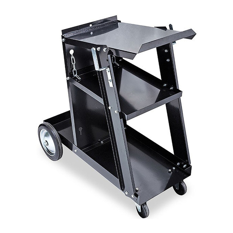
PROFESSIONAL WELDING CART
INSTRUCTIONS
Item #20354
© Copyright 2015 Easthill Group, Inc. 9/15 Instruction Item #20354Q Rev 1
If you have any questions about the use of this product, please contact
The Eastwood Technical Assistance Service Department: 800.544.5118 >> email: techelp@eastwood.com
PDF version of this manual is available online >> eastwood.com/20354manual
The Eastwood Company 263 Shoemaker Road, Pottstown, PA 19464, USA
US and Canada: 800.345.1178 Outside US: 610.718.8335
Fax: 610.323.6268 eastwood.com
ATTACH CABLE/HOSE STORAGE BRACKETS (“I”) TO UPPER FRAME – FIG. 7
1. From the underside locate the (3) Cable/Hose Storage Brackets (“I”) into the holes in either side
of The Upper Frame.
2. Attach 10mm flange nuts over the threads protruding through. Tighten with a 14mm wrench.
3. Using a 14mm wrench, tighten all nuts securely.
ASSEMBLE TOOL STORAGE TRAYS (“J/K”) – FIG. 8
1. Arrange (2) Trays (“J” ) with flanges facing upward, place against the flat faces of (2) Uprights
(“K”) and align the (4 ) mounting holes.
2. From the backside of each Upright (“K”), insert 6mm x 20mm bolts & attach 6mm flange nuts over
the threads protruding inward through the Trays (“J” )
3. Using a 4mm hex key and 10mm wrench, tighten all (4) bolt, washer and nut sets securely.
ATTACH TOOL STORAGE TRAY ASSEMBLY (“J/K”) TO UPPER FRAME – FIG. 9
1. Locate the Tool Storage Tray Assembly (“J/K”) into the 2 of the holes in either side of The Upper
Deck Assembly Frame.
2. Place flange nuts over the 10mm threads protruding through.
3. Using a 14mm wrench, tighten all nuts securely.
INSTALL UPPER & LOWER CYLINDER RETAINING HOOPS (“G” & “H”) – FIG. 6
1. Slip the (2) Lower Cylinder Retaining Hoops (with threaded ends) (“G”) into holes in Lower Frame
crossmember (under “H” Member). NOTE: The Hoops must face the rear of the cart. Attach 10mm
flange nuts over the threads protruding through and tighten securely with a 14mm wrench.
2. Place 2 Gas Cylinders into Lower Hoops.
3. Slip (2) Upper Cylinder Retaining Hoops (with pinned ends) (“H”) over the 2 Gas Cylinders and
place the ends into holes in “H” Member cross bar. Secure by pushing Spring Pins through holes
in Hoop Ends.
FIG. 9
FIG. 8
FIG. 7
FIG. 6
Your Eastwood Professional 4 wheel Welding Cart is now ready for use.
H
G
H
G
I
J
K
2Eastwood Technical Assistance: 800.544.5118 >> techelp@eastwood.com To order parts and supplies: 800.345.1178 >> eastwood.com 3
ASSEMBLY
REAR WHEELS TO LOWER DECK ASSEMBLY (“C” TO “A”)
1. Slide Axle (“B”) through welded tubes on underside of Lower Frame (“A”).
2. Place Wheels (“C”) onto Axle (“B”).
3. Place large washers over Axle between wheel hub and cotter pin. (“B”).
4. Insert cotter pins into holes in either end of Axle (“B”), bend legs backward over wheel hubs
with pliers.
INCLUDES
Components: Hardware:
(1) Lower Deck Assembly, “A” (2) Wheel Retaining Washers
(1) Axle, “B” (2) Cotter Pins
(2) 7-1/2" Wheels, “C” (4) Upper Tank Retaining Hoop Spring Pins
(1) Frame “H” Member, “D” (4) 6mm x 20mm Bolts
(1) Upper Deck Assembly, “E” (4) 6mm x 40mm Bolts
* (2) Upper Deck Supports, (“F”- Left) & (“F”- Right) (8) 6mm Flange Nuts
(2) Lower Tank Retaining Hoops, “G” (8) 8mm x 50mm Bolts
(2) Upper Tank Retaining Hoops, “H” (4) 8mm Flange Nuts
(3) Universal Cable/Hose Storage Brackets, “I” (9) 10mm Flange Nuts
(2) Tool Storage Trays, “J”
(2) Tool Storage Tray Uprights, “K”
* NOTE: This cart will fit many welder brands other than Eastwood’s. The Deck Supports “F” can be interchanged left and right as required.
TOOLS REQUIRED
• 10, 12 & 14mm wrenches
• 4 & 5mm hex keys
• Pliers
The Eastwood Professional Welding Cart is constructed of heavy-gauge, powder-coated steel to provide years of rugged and reliable service. It is designed
to hold all Eastwood MIG or TIG welders and Eastwood Plasma Cutters along with required gas cylinders. Includes quick-release gas cylinder retaining hoops for
safety, large 7-1/2" rubber-tired wheels for stability and ball-bearing swivel casters for easy mobility.
SAFETY INFORMATION
READ INSTRUCTIONS!
• Read this entire manual before set up and use.
• Keep this manual for future reference.
WARNING!
• This cart is intended for use with 7" diameter cylinders up to 43" in height (125 cu. ft.). Do not use with larger cylinders. Use caution
when handling compressed gas cylinders and always keep in the upright position. Always use supplied Cylinder Retaining Hoops to
secure the cylinders to the cart at top and bottom.
• Use cart on level surfaces only. Do not use on sloped surfaces.
• Always push, pull and steer the cart by the top shelf only and be aware that the weight of a welder will cause it to be top heavy. Do not
push, pull or steer the cart by the welder case, welder gun, ground cable, or gas cylinders, as it could cause the cart to tip over.
• Never clamp ground clamp to cart as it could complete the welding circuit and cause unexpected arcing.
• The maximum weight capacity of the top shelf is 100 lbs. Do not exceed this weight or cart failure and personal injury could result.
“H” MEMBER & UPPER DECK ASSEMBLY (“D”) & (“E”), TO LOWER DECK ASSEMBLY (“A”) – FIG. 3
1. Place the “H” Member saddles over the holes in the Lower Deck Assembly Frame (“A”), and
align all holes.
2. Insert (4) 8mm x 50mm bolts downward through the topside of the “H” member saddles and Lower
Deck Assembly Frame. Attach flange nuts over the threads protruding through.
3. Tighten nuts only “finger-tight” to allow for alignment in following steps.
UPPER DECK ASSEMBLY (“E”), TO “H” MEMBER (“D”) – FIGS. 1&2
IMPORTANT NOTE: Some difficulty may be encountered at this step of the assembly due to the included
angles of the Upper and Lower tube sections. It is highly recommended to have a helper present for this
step. It will be necessary to push the Swaged ends of the “H” Member outward while pulling the open
ends of the Upper Deck Downtubes.
A ratcheting strap works well with pulling in the open ends of the Upper Deck Downtubes.
1. Turn the Upper Deck Assembly upside down on a piece of cardboard from the packaging.
2. Place the open downtubes of the Upper Deck Assembly over the swaged upper ends of the “H”
Member (“A”) and align all holes.
3. As noted above, it will be necessary to push the angled, swaged ends of the “H” Member outward
to allow them to fit into the angled ends of the Upper Deck Assembly.
4. Insert (4) 6mm x 40mm bolts inward through the Upper Deck Assembly Downtubes and the ”H”
member swaged ends. Attach 6mm flange nuts over the threads protruding through.
5. With a 4mm hex key and 10mm wrench, draw up the hardware only “finger-tight” to allow for
alignment in following steps.
UPPER DECK ASSEMBLY SUPPORTS (“F”–LEFT) & (“F”–RIGHT), BETWEEN UPPER & LOWER DECK
ASSEMBLY FRAMES – FIGS. 4 & 5
NOTE: This cart will fit many welder brands other than Eastwood’s. The Deck Supports “F” can be
interchanged left and right as required.
1. Align the Upper Deck Supports with threaded ends with holes in Upper and Lower Deck Assembly
Frame Tubes. NOTE: The Tool/Rod Holder Tubes of the Right Upper Deck Assembly Support
(“F–Right”) must face outward.
2. Place the 8mm x 50mm bolts through holes in Upper and Lower Deck Assembly Frames and
thread into the ends of the Upper Deck Supports.
3. With a 5mm hex key, tighten bolts only “finger-
tight” to allow for alignment of entire assembly
at this point. Once the components are properly
aligned, all fasteners can be tightened securely.
FIG. 4
FIG. 3
FIG. 2
FIG. 1
FIG. 5
D
E
D
E
DE
D
F
A
A
F
D
E

PROFESSIONAL WELDING CART
INSTRUCTIONS
Item #20354
© Copyright 2015 Easthill Group, Inc. 9/15 Instruction Item #20354Q Rev 1
If you have any questions about the use of this product, please contact
The Eastwood Technical Assistance Service Department: 800.544.5118 >> email: techelp@eastwood.com
PDF version of this manual is available online >> eastwood.com/20354manual
The Eastwood Company 263 Shoemaker Road, Pottstown, PA 19464, USA
US and Canada: 800.345.1178 Outside US: 610.718.8335
Fax: 610.323.6268 eastwood.com
ATTACH CABLE/HOSE STORAGE BRACKETS (“I”) TO UPPER FRAME – FIG. 7
1. From the underside locate the (3) Cable/Hose Storage Brackets (“I”) into the holes in either side
of The Upper Frame.
2. Attach 10mm flange nuts over the threads protruding through. Tighten with a 14mm wrench.
3. Using a 14mm wrench, tighten all nuts securely.
ASSEMBLE TOOL STORAGE TRAYS (“J/K”) – FIG. 8
1. Arrange (2) Trays (“J” ) with flanges facing upward, place against the flat faces of (2) Uprights
(“K”) and align the (4 ) mounting holes.
2. From the backside of each Upright (“K”), insert 6mm x 20mm bolts & attach 6mm flange nuts over
the threads protruding inward through the Trays (“J” )
3. Using a 4mm hex key and 10mm wrench, tighten all (4) bolt, washer and nut sets securely.
ATTACH TOOL STORAGE TRAY ASSEMBLY (“J/K”) TO UPPER FRAME – FIG. 9
1. Locate the Tool Storage Tray Assembly (“J/K”) into the 2 of the holes in either side of The Upper
Deck Assembly Frame.
2. Place flange nuts over the 10mm threads protruding through.
3. Using a 14mm wrench, tighten all nuts securely.
INSTALL UPPER & LOWER CYLINDER RETAINING HOOPS (“G” & “H”) – FIG. 6
1. Slip the (2) Lower Cylinder Retaining Hoops (with threaded ends) (“G”) into holes in Lower Frame
crossmember (under “H” Member). NOTE: The Hoops must face the rear of the cart. Attach 10mm
flange nuts over the threads protruding through and tighten securely with a 14mm wrench.
2. Place 2 Gas Cylinders into Lower Hoops.
3. Slip (2) Upper Cylinder Retaining Hoops (with pinned ends) (“H”) over the 2 Gas Cylinders and
place the ends into holes in “H” Member cross bar. Secure by pushing Spring Pins through holes
in Hoop Ends.
FIG. 9
FIG. 8
FIG. 7
FIG. 6
Your Eastwood Professional 4 wheel Welding Cart is now ready for use.
H
G
H
G
I
J
K

Other Eastwood Outdoor Cart manuals

Eastwood 30551 User manual

Eastwood

Eastwood 30551 User manual

Eastwood 20232 User manual

Eastwood

Eastwood 20232 User manual

Eastwood 31490 User manual

Eastwood

Eastwood 31490 User manual

Eastwood 31539 User manual

Eastwood

Eastwood 31539 User manual

Popular Outdoor Cart manuals by other brands

Gorilla Carts 7GCG-NF user manual

Gorilla Carts

Gorilla Carts 7GCG-NF user manual

Gorilla Carts GCG-7 manual

Gorilla Carts

Gorilla Carts GCG-7 manual

Bartscher 300105 instruction manual

Bartscher

Bartscher 300105 instruction manual

VYPER ROBUST STEEL SPORT Assembly guide

VYPER

VYPER ROBUST STEEL SPORT Assembly guide

Metro DataVac LODGIX LXHR-PRO manual

Metro DataVac

Metro DataVac LODGIX LXHR-PRO manual

Husky WHEEL BARROW 1006456732 instruction manual

Husky

Husky WHEEL BARROW 1006456732 instruction manual

WERKU WK602360 Original instructions

WERKU

WERKU WK602360 Original instructions

AxcessAbles DOLLY manual

AxcessAbles

AxcessAbles DOLLY manual

Demco 1722 Operator's manual

Demco

Demco 1722 Operator's manual

Craftsman 486.24339 owner's manual

Craftsman

Craftsman 486.24339 owner's manual

Sunex Tools 8057PK Assembly instructions

Sunex Tools

Sunex Tools 8057PK Assembly instructions

S&S Worldwide W12348 Assembly instructions

S&S Worldwide

S&S Worldwide W12348 Assembly instructions

U-Line H-9093 quick start guide

U-Line

U-Line H-9093 quick start guide

Bretford FP42ULC user manual

Bretford

Bretford FP42ULC user manual

MSW MSW-LTC500 user manual

MSW

MSW MSW-LTC500 user manual

Konig & Meyer 18860 quick start guide

Konig & Meyer

Konig & Meyer 18860 quick start guide

Costway TL32912 user manual

Costway

Costway TL32912 user manual

Dolomite Jazz operating instructions

Dolomite

Dolomite Jazz operating instructions

manuals.online logo
manuals.online logoBrands
  • About & Mission
  • Contact us
  • Privacy Policy
  • Terms and Conditions

Copyright 2025 Manuals.Online. All Rights Reserved.