Easy Controls MC732 User manual

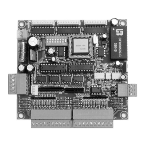
MC732 INPUT/OUTPUT BOARD
1www.easy-controls.com
MC732 INPUT/OUTPUT BOARD
Features
On board opto-isolated RS485 interface.
4 dry contact inputs, each with a red LED for status indication.
(common ground)
All inputs have owner state changed timeout setting for improved
input noise rejection.
4 on-board relay outputs, each with a LED for status indication
To save power, status indication LED can be auto turned off.
Support i-Control System
Support Easy Control
ProvideActiveX Control for your application software.
User's Manual
DEVICE CODE: 732

MC732 INPUT/OUTPUT BOARD
2www.easy-controls.com
IMPORTANT
Although the information contained herein has been carefully verified,
NEWELL TECHNOLOGIES LIMITED assumes no responsibility for any
errors that may occur, for any damage to property or persons resulting
from improper use of this manual or from the related software. NEWELL
TECHNOLOGIES LIMITED products are not authorized for use as
components in medical, life support or military devices. No patent
licenses are implied. NEWELL TECHNOLOGIES LIMITED reserves the
right to change the features and specifications without notice at any
time.

MC732 INPUT/OUTPUT BOARD
3www.easy-controls.com
Document overview
Connectors ........................................................................................................................................................ 4
PCB Size ........................................................................................................................................................... 5
Technical Specifications..................................................................................................................................... 5
Power Supply (J1/J2)......................................................................................................................................... 6
Reset.................................................................................................................................................................. 6
Communication Interface (J4) ........................................................................................................................... 6
Input Connection (J3) ........................................................................................................................................ 6
Output Connector (J5, J6, J7, J8)...................................................................................................................... 6
Device ID ........................................................................................................................................................... 7
Easy Control Resource...................................................................................................................................... 7
Properties Settings.................................................................................................................................... 7
System variable......................................................................................................................................... 7
Data for remote reading............................................................................................................................ 7
System Startup Delay Jumper (JP1)......................................................................................................... 7
Device Code.............................................................................................................................................. 7
Develop Application Software............................................................................................................................ 7
Customer service............................................................................................................................................... 7

MC732 INPUT/OUTPUT BOARD
4www.easy-controls.com
Connectors
4
3
2
1
Input Common
Input 1~4
Output 1~4
*Power supply(J1)
System Startup Delay
Jumper JP1
RS232 Connector
Output Status LED
*Power supply(J2) Input Status LED
Notes:
* Only one power-supply can be connected to J1 or J2.
System Status LED
Communication Status LED
J1
J2
J3
J4
J5
J6
J7
J8
NC
COM.
N
O
NC
COM.
N
O
NC
COM.
N
O
NC
COM.
N
O
Output 1
Output 2
Output 3
Output 4

MC732 INPUT/OUTPUT BOARD
5www.easy-controls.com
PCB Size
Technical Specifications
Maximum boards
(In same control network)
256(addressed by device ID)
more than 256 (addressed by serial number)
Inputs 4 (dry contact)
Outputs 4 (Relays)
Max switching current /voltage: 4A/60VDC, 4A/60VAC
Communication Interface RS485
Power supply 8-30 VDC 10W
Consumption 4 W (max)
Dimensions 87x 104.5 mm
104.5mm
87mm
φ4.5mm
7.5mm

MC732 INPUT/OUTPUT BOARD
6www.easy-controls.com
Power Supply (J1/J2)
The device requests a DC power supply and connect to J1 or J2.
DC: 8 –30 V 10W
Using J1
J1 Pin Description
1 V+
2 GND
Using J2
Reset
The device reset and set default output state at power-up, the state of the outputs does not change even a
system software or hardware reset (Watchdog Timer - WDT) may occur.
There is no any reset button on the device, Watchdog Timer (WDT) has been installed in the device.
Communication Interface (J4)
The device built in opto-isolated RS232 interface and the connector is J4, the baud rate can be software
configured.
Input Connection (J3)
The device has 4 dry contact inputs, each has two statuses, one is open, another is short to
COMMON. All inputs have same features and can be configured by software.
Connectors: J3. Refer to Connectors.
Note: All COMMON are connected to Ground of the device.
Output Connector (J5, J6, J7, J8)
The device features 4 on-board relays.
Max switching current/voltage: 4A/60VAC, 4A/60VDC
Connector: J5, J6, J7, J7. Please refer to Connectors.
V+
GND

MC732 INPUT/OUTPUT BOARD
7www.easy-controls.com
Device ID
The default Device ID is 0, the ID can be changed by set system variable IDEX, Please refer to Easy Control
manual.
Easy Control Resource
Please install software [Easy Control]. To download the newest version, you can go to
http://www.easy-controls.com/download/
Properties Settings
Choose the menu [Device] - [Properties] to open the dialog window and press button [Help] to get the detail of
the settings.
System variable
Choose the menu [Device] - [Resource] to get the list of the variable in the system.
Data for remote reading
Choose the menu [Device] - [Resource] to get the detail.
System Startup Delay Jumper (JP1)
Short the jumper, system will delay five seconds to start, if you have trouble to upload new program to the
device after system start, you can upload new program to the device in this period.
Device Code
Device code is 732.
Develop Application Software
To develop your owner application software, you need to install Mcioctrl2.0 ActiveX Control, you can
download the ActiveX Control, user’s manual and sample code from website
http://www.easy-controls.com/download/.
Customer service
You can access Customer Service support through the following avenue.
Tel: (852)-27827895
Fax: (852)-27825650
Email: support@ easy-controls.com
http://www.easy-controls.com
Table of contents
Other Easy Controls Computer Hardware manuals
Popular Computer Hardware manuals by other brands

AJA
AJA KONA LHI Installation and operation guide

DFI
DFI CS551-Q370 quick reference

Acksys
Acksys AirXroad/4P Hardware installation

TC-Helicon
TC-Helicon VoicePro instruction manual

StarTech.com
StarTech.com 1P3FFCB-USB-SERIAL quick start guide

Data Translation
Data Translation DT300 Series Getting started manual

Texas Instruments
Texas Instruments MSP-FET430 user guide

Renesas
Renesas RX13T user manual

Arbor Technology
Arbor Technology EmETXe-i89U0 user manual

NEC
NEC FDl165 Product description

Moxa Technologies
Moxa Technologies CP-602U-I-T Quick installation guide

Mellanox Technologies
Mellanox Technologies SX1710 quick start guide