Eaton CI-K NA Series Manual

Emergency On Call Service:Local representative (Eaton.eu/aftersales)or +49 (0)180 5223822 (de, en) 1/7
Instruction Leaflet
Montageanweisung
Notice d’installation
Instrucciones de montaje
Istruzioni per il montaggio
安安装说明装说明
Инструкция по монтажу
05/18 IL01502082Z
CI-K…-NA
Installation of conduits and grounding of equipmentenclosures.
These enclosuresare intended for wall mounting only!
Table: Technical data conduit
Select the size and location of conduits on the
enclosure and provide conduit holes according to
Instructions shown in table.
Connect conduits to the enclosures according to
the instructions shown in figures 1.
For grounding of equipment, install the grounding
conductor in accordance with the requirements of
the National Electric Code (N.E.C. – USA)or
Canadian Electric Code (C.E.C. – Canada).
Figure 1
Connection of metallic and non-metallic conduits
Maximum permissiblesize of
conduit entry
CI-K2X…-NA
2 x ½“ Conduit
CI-K3X…-NA
2 x ¾“ Conduit
CI-K4X…-NA
2 x 1“, 1 x ½“ Conduit
CI-K5X…-NA
2 x 1½“, 1x½“ Conduit
aConnector hub
bUse trade size conduit fittings
cGrounding conductor
dEquipment grounding terminal
eLocknut
Conduit trade size inches½¾1 1–¼1– ½
Hole diameterinches 7/81 – 11/81 – 13/81 – ¾2
mm 22 28 35 44 50
Electric current! Danger to life!
Only skilled or instructedpersons maycarryout the
following operations.
en
1 2 3
CAUTION
Empty enclosures and enclosures used with
switches for the North Americanmarket
have no knock-outs in the end walls of the
enclosure. Conduit entries must be drilled to
suit as shown. The metric size conduit
entries which appear in product dedicated
IL… Instruction Leaflet supplied with
enclosed switchesdo notapply to
North American switch enclosures.
en
a
e
d
c
b
CAUTION
First secure the connector hub onto the conduit.
Then secure conduit with connectorhub into the
enclosure hole, using the locknut for fixing.
Bonding andgrounding bushings arenot required.
en

2/7Emergency On Call Service: Local representative (Eaton.eu/aftersales)or +49(0) 1805223822 (de, en)
05/18 IL01502082Z
CI-K…-NA
Leitungsinstallation undErdung der Gerätegehäuse.
Diese Gehäuse sind ausschließlich für die Wandmontage!
Tabelle: Technische Daten Installationsrohr
Wählen Sie die entsprechende Größe und
Position des Installationsrohrs auf demGehäuse
ausund stellen Sie die Bohrungen für das
Installationsrohr wie in der Tabelle beschrieben
her.
Verbinden Sie die Installationsrohre mit dem
Gehäuse, wie in Abbildung 1 beschrieben.
Installieren Sie den Schutzleiter der Geräte
entsprechend den Anforderungen
National Electric Code (N.E.C. –USA) oder
dem CanadianElectric Code (C.E.C. –Canada).
Abbildung 1
Verbindung von metallischen und
nicht-metallischen Installationsrohren
Maximal zulässige Größe der
Installationsrohreinführung
CI-K2X…-NA
2 x ½“ Installationsrohr
CI-K3X…-NA
2 x ¾“ Installationsrohr
CI-K4X…-NA
2x 1“, 1x ½“ Installationsrohr
CI-K5X…-NA
2x 1½“, 1 x ½“ Installationsrohr
aVerschraubung
bVerwenden Sie handelsübliche Installations-
rohrbeschläge
cErdungsleiter
dErdungsklemme
eSicherungsmutter
Handelsübliche
Installationsrohrgrößen
Zoll ½¾11–¼1– ½
Bohrungsdurchmesser Zoll 7/81 – 11/81 – 13/81 – ¾2
mm 22 28 35 44 50
Lebensgefahr durch
elektrischen Strom!
Nur Elektrofachkräfteund elektrotechnisch
unterwiesene Personen dürfen die im Folgenden
beschriebenen Arbeiten ausführen.
de
1 2 3
VORSICHT
Leergehäuse und Gehäuse mit Schalternfür
den nordamerikanischen Markt besitzen
keine Vorprägungen auf der Rückwand des
Gehäuses. Bohrungen für Installationsrohre
müssen entsprechend gebohrt werden
(siehe Abbildung).
Die Installationsrohr-
einführungenfür metrische Größen, wie in der
Montageanweisung desProdukts mit der
Bezeichnung IL… beschrieben, welches mit
vorinstallierten Schaltern geliefert wird, gilt
nicht fürGehäuse mit Schaltern für den nord-
amerikanischen Markt.
de
a
e
d
c
b
VORSICHT
Verschrauben Sie zuerst das Installationsrohr
mit der Verschraubung.
FührenSie dann das Installationsrohr mit der
Verschraubung in die Bohrung desGehäusesein
und sichern diesesmit der Sicherungsmutter.
Verbindungs- oder Erdungsbuchsen sind nicht
erforderlich.
de

Emergency On Call Service:Local representative (Eaton.eu/aftersales)or +49 (0)180 5223822 (de, en) 3/7
05/18 IL01502082Z
CI-K…-NA
Montage de tubes conducteurs et mise à la terre d’appareils incorporés dans des coffrets isolants.
Les coffrets sont exclusivement destinés à un montage encastré!
Tableau : Données des canalisations
Déterminer la taille et les points de raccordement
des tubes conducteursau niveau du coffret.
Préparer les trous d’insertion correspondants
(selon tableau).
Raccorder chaque tube conducteur selon les
indications des figures 1.
Le conducteur de terre destiné à la mise à la terre
des appareilsincorporés doit être installé
conformément aux prescriptions du «National
Electric Code»(N.E.C. –USA) ou du «Canadian
ElectricCode » (C.E.C. – Canada).
Figure 1
Raccordementde tubes conducteurs
métalliques et non-métalliques
Entrée de câbles max. admise
CI-K2X…-NA
2 x ½“ Conduit pour câbles
CI-K3X…-NA
2 x ¾“ Conduit pour câbles
CI-K4X…-NA
2 x 1“, 1 x ½“ Conduit pour câbles
CI-K5X…-NA
2 x 1½“, 1 x ½“ Conduit pour câbles
aMilieu du raccord
bUtiliser des raccords courants du commerce
cConducteur de terre
dBorne de mise àla terre des appareils
eContre-écrou
Tailles courantes des
tubes conducteurs
Pouces ½¾11–¼1– ½
Diamètres de perçage Pouces 7/81 – 11/81 – 3/81 – ¾2
mm 22 28 35 44 50
Tensionélectriquedangereuse!
Seulesles personnes qualifiéeset avertiesdoivent
exécuterles travaux ci-après.
fr
1 2 3
AVERTISSEMENT
Les boîtiers vides et les boîtiers avec
disjoncteurs destinés au marché nord-
américain n’ont pasde prédécoupes
défonçables dans la face arrière.
Les entrées de câblesdoivent êtrepercées
comme illustré. La notice de montage IL…
fournie audisjoncteur sous enveloppe
indique des entrées de câbles avec des
dimensions métriques non valablespour
les boîtiersnord-américains.
fr
a
e
d
c
b
AVERTISSEMENT
Fixer tout d’abord le milieu du raccord sur le
tube conducteur.
Insérer ensuite l’ensemble tubeconducteur/milieu
du raccord dans le trou du coffret,puis le fixer àl’aide
du contre-écrou. Il est inutile de faire appelàdes
manchons d’équipotentialité et de mise àla terre.
fr

4/7Emergency On Call Service: Local representative (Eaton.eu/aftersales)or +49(0) 1805223822 (de, en)
05/18 IL01502082Z
CI-K…-NA
Instalación de conductos y puesta a tierra de envolventes del equipamiento.
¡Estos envolventes sólo se han previsto para montaje mural!
Table: Datos delconducto
Seleccione el tamaño y ubicación delos
conductosen el envolvente y prepare agujeros
para los conductos según las Instrucciones
indicadas en la tabla.
Conecte los conductosen losenvolventessegún
las instrucciones indicadas en la figura 1.
Para la puesta a tierra de equipamiento, instale el
conductor de puesta atierra según los requisitos
del Código Eléctrico Nacional (N.E.C. – EE.UU.)
odel Código Eléctrico Canadienese
(C.E.C. – Canadá).
Figura 1
Conexión de conductos metálicosy
no metálicosconductos
Tamaño máximo admisible de
la entrada del conducto
CI-K2X…-NA
2 x ½“ Conducto
CI-K3X…-NA
2 x ¾“ Conducto
CI-K4X…-NA
2x 1“, 1x ½“ Conducto
CI-K5X…-NA
2x 1½“, 1 x ½“ Conducto
aManguito conector
bUtilice accesorios de losconductos
de tamaño comercial
cConductor de puesta a tierra
dTerminal de puesta atierradel equipamiento
eContratuerca
Tamaño comercial
del conducto
pulgadas½¾1 1 – ¼1– ½
Diámetro del agujero pulgadas 7/81 – 11/81 – 13/81 – ¾2
mm 22 28 35 44 50
¡Corrienteeléctrica!
¡Peligro de muerte!
El trabajo acontinuación descritodebe ser
realizado por personas cualificadas y advertidas.
es
1 2 3
ATENCIÒN
¡Los envolventes vacíos y envolventes
utilizados con interruptores para el mercado
norteamericano no poseen pretaladros en
las paredes finales del envolvente.
Las entradas del conducto deben perforarse
para que se ajusten según indicado.
Las entradas delconducto de tamaño
métrico que aparecen en las Instrucciones
de instalación dedicadas al producto IL…
suministradas con los interruptores bajo
envolvente no son aplicables para los
envolventes deinterruptornorteamericanos.
es
a
e
d
c
b
ATENCIÒN
En primer lugar, fije el manguito conector
en el conducto.
A continuación, fije el conducto con el manguito
conector en el agujero del envolventeutilizando
la contratuerca para su fijación. No se necesitan
casquillos de unión ni de puesta a tierra.
es

Emergency On Call Service:Local representative (Eaton.eu/aftersales)or +49 (0)180 5223822 (de, en) 5/7
05/18 IL01502082Z
CI-K…-NA
Installazione delle linee e messa a terra delle custodie degli apparecchi.
Le custodie sono da montare esclusivamente a muro!
Tabella: dati tecnici sul condotto
Scegliere le dimensioni e la posizione del condotto
sulla custodia e praticare i fori per il condotto,
come descritto in tabella.
Collegare i condotti alla custodia, come descritto
in figura 1.
Installare il conduttore di terra degli apparecchi in
base ai requisiti del National Electric Code
(N.E.C. –USA) o del Canadian Electric Code
(C.E.C. –Canada).
Figura 1
Collegamento di condotti metallici e non metallici
Dimensioni massime consentite
dell’ingresso del condotto
CI-K2X…-NA
2 x ½“ condotti
CI-K3X…-NA
2 x ¾“ condotti
CI-K4X…-NA
2 x 1“, 1 x ½“ condotti
CI-K5X…-NA
2 x 1½“, 1x½“ condotti
acollegamento a vite
butilizzare guarnizioni per condotti reperibili in
commercio
cconduttore di messa a terra
dmorsetto di messa aterra
econtrodado di sicurezza
Dimensioni dei condotti
reperibili in commercio
Pollice½¾1 1 – ¼1– ½
Diametro foroPollice 7/81 – 11/81 – 13/81 – ¾2
mm 22 28 35 44 50
Tensione elettrica:
Pericolo di morte!
Solo persone abilitate e qualificatepossono
eseguire le operazioni di seguito riportate.
it
1 2 3
ATTENZIONE
Le custodie vuote e le custodie con interruttori
destinate al mercato nordamericano non hanno
prestampaggi in rilievo sulla parete posteriore
della custodia. I fori per i condotti devono
essere praticati comeillustrato in figura. Gli
ingressi dei condotti per grandezze metriche,
come descritto nella guida all’installazione del
prodotto denominato IL…, dotato di interruttori
preinstallati, non si applicano agli interruttori
destinati al mercato nordamericano.
it
a
e
d
c
b
ATTENZIONE
Fissare prima il condotti con il collegamento
a vite.
Introdurre quindi il condotto con il collegamento
avite nel foro della custodia e fissarlo con il
controdado di sicurezza. Non sono necessarie
boccole di collegamento o di messa a terra.
it

6/7Emergency On Call Service: Local representative (Eaton.eu/aftersales)or +49(0) 1805223822 (de, en)
05/18 IL01502082Z
CI-K…-NA
设备外壳的电缆安装与接地。设备外壳的电缆安装与接地。
这个设备外壳只用于墙式安装方式这个设备外壳只用于墙式安装方式
表格:安装管道的技术数据表格:安装管道的技术数据
在设备外壳上为安装管道选择相应的安装尺
寸和位置,并按照下表所示为安装管道钻孔。
按照图1所示连接安装管道与设备外壳。 根据美国电气编码 (N.E.C.– 美国)或者加
拿大电气编码(C.E.C.– 加拿大)的规范要
求安装设备的保护电缆。
图1图1
安装管道的金属和非金属连接安装管道的金属和非金属连接
安装管道进入口的最大允许尺寸安装管道进入口的最大允许尺寸
CI-K2X…-NA
2x½“ 安装管道
CI-K3X…-NA
2x¾“ 安装管道
CI-K4X…-NA
2x 1“, 1x ½“ 安装管道
CI-K5X…-NA
2x 1½“, 1 x ½“ 安装管道
a螺栓连接
b使用商业上通用的安装管道连接件
c接地导线
d接地夹
e锁紧螺母
商用安装管道尺寸 英寸 ½¾11–¼1– ½
钻孔直径英寸 7
/
8
1 – 11/81 – 13/81 – ¾2
Mm 22 28 35 44 50
触电危险!触电危险!
只允许专业人员和受过专业训练的人员进行
下列工作。
zh
1 2 3
小心小心
用于北美市场的带开关的空外壳和设备
外罩在外壳后面板上没有前压印。安装
管道孔必须按照相关要求钻好 (见图
示)。安装管道进入口的金属尺寸如产品
安装手册中的标记 IL 所示 …,与预先安
装的开关同时提供,不适用于北美市场
带开关的设备外壳。
zh
a
e
d
c
b
小心小心
首先将安装管道用螺栓拧紧。
然后将带螺栓连接的安装管道装入设备外壳上
的安装孔并用锁紧螺栓拧紧。
不需要连接或接地套管。
zh

Emergency On Call Service:Local representative (Eaton.eu/aftersales)or +49 (0)180 5223822 (de, en) 7/7
05/18 IL01502082Z
EatonIndustries GmbH, Hein-Moeller-Straße 7-11, 53115 Bonn, Germany
©2001 by Eaton Industries GmbH, Eaton.eu/documentation
Eaton.com/recycling
All Rights Reserved 05/18IL01502082Z
CI-K…-NA
Подключение проводов изаземление корпуса устройства.
Этот корпус предназначен толькодлянастенного монтажа!
Таблица: техн.характеристики монтажной трубы
Выберите соответствующий размер и
расположение монтажнойтрубына корпусеи
просверлите отверстия для монтажной трубы,
как описано в таблице.
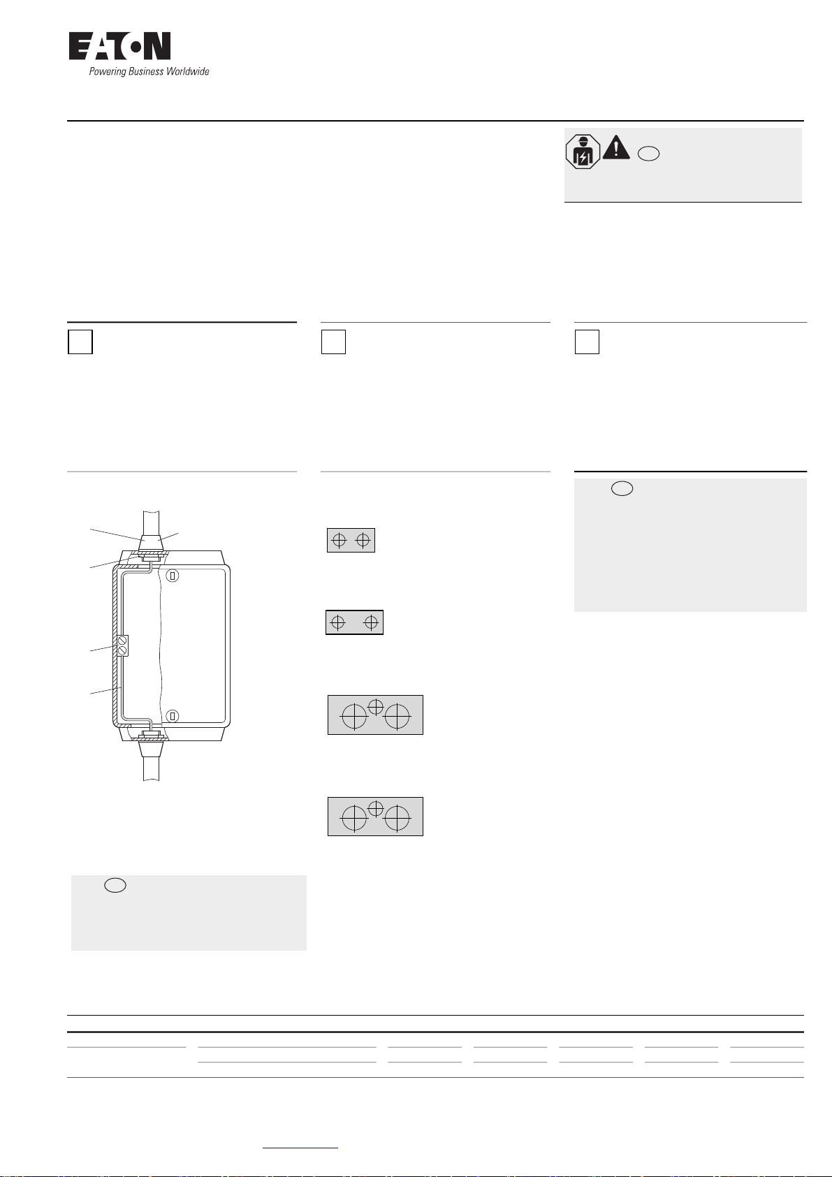
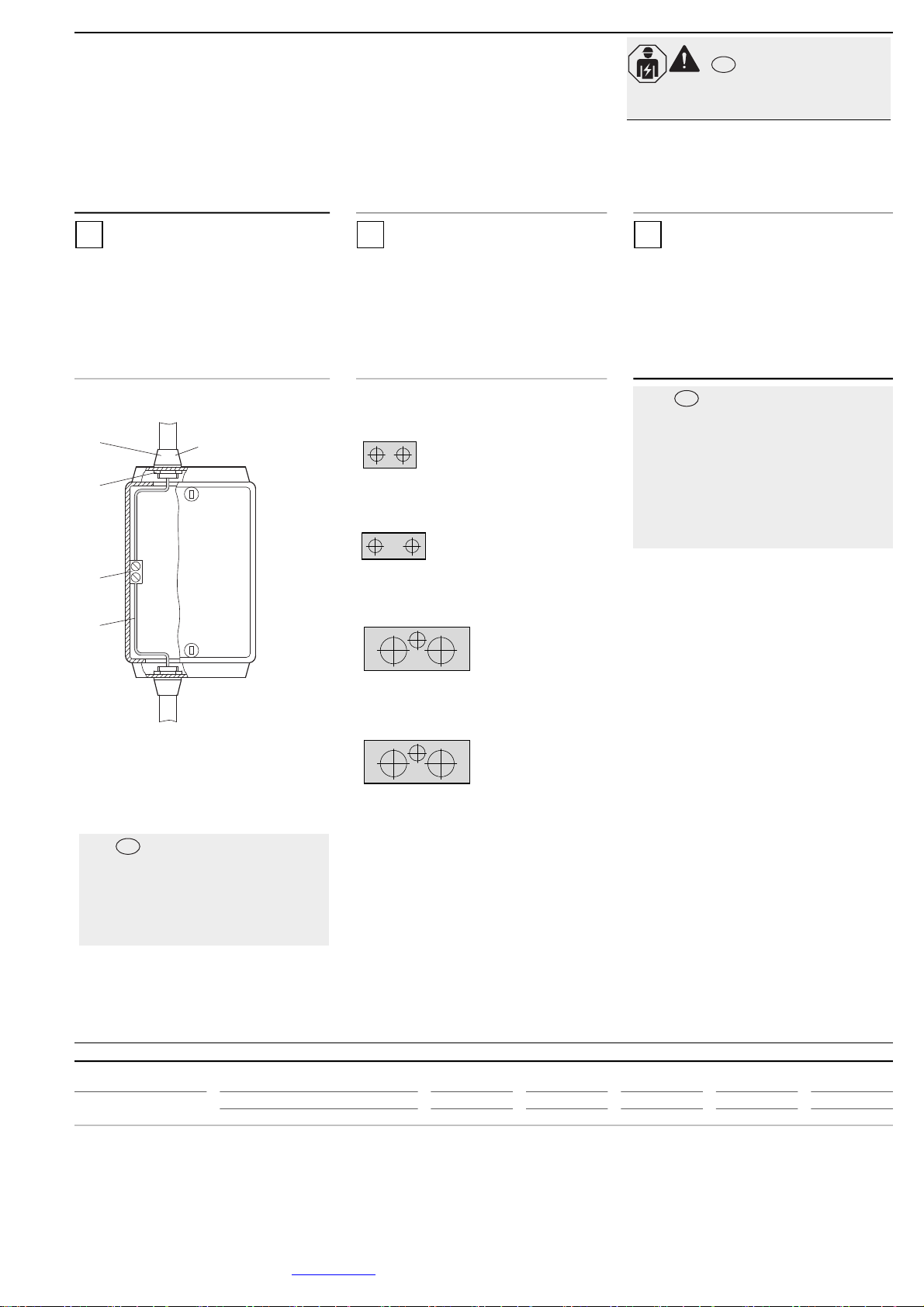
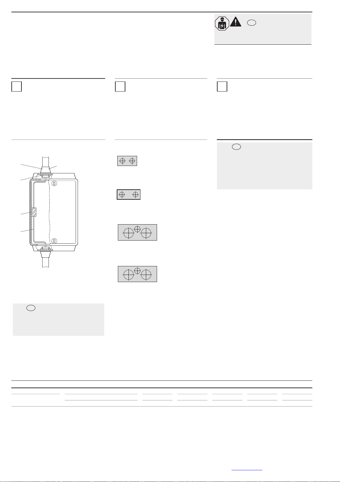
Соедините монтажную трубу с корпусом, как
показано на рис. 1.
Подсоедините защитныйпровод устройств
согласно требованиям Национальных правил
установки электрооборудования
(N.E.C. –США)или Канадских правил установки
электрооборудования
(C.E.C. – Канада).
Рис. 1
Соединение металлических и
неметаллическихмонтажных труб
Макс. допустимый размер ввода
монтажной трубы
CI-K2X…-NA
Монтажная труба, 2 x ½“
CI-K3X…-NA
Монтажная труба, 2 x ¾“
CI-K4X…-NA
Монтажная труба, 2 x 1“, 1 x ½“
CI-K5X…-NA
Монтажная труба, 2 x 1½“, 1x½“
aРезьбовоесоединение
bИспользуйте стандартный трубный крепеж
cЗаземляющийпровод
dКлемма заземления
eКонтргайка
Стандартные
установочные размеры
дюймы ½¾11–¼1– ½
Диаметр отверстия дюймы 7/81 – 11/81 – 13/81 – ¾2
мм 22 28 35 44 50
Электрический ток!
Опаснодля жизни!
Только специалистыили проинструктированные
лица могут выполнятьследующие операции.
ru
1 2 3
ОСТОРОЖНО
Пустые корпуса икорпусас
выключателямидля
североамериканского рынканеимеют
выштамповок на заднейстенке корпуса.
Необходимо просверлить
соответствующие отверстия для
монтажныхтруб (см. рис.).
Вводымонтажных труб дляметрических
размеров, описанные винструкциипо
монтажуизделия снаименованием IL…,
которое поставляетсяспредварительно
смонтированными выключателями,
недействительны для корпусов с
выключателями для
североамериканского рынка.
ru
a
e
d
c
b
ОСТОРОЖНО
Сначала требуется закрепить монтажную
трубусрезьбовымсоединением.
Затем монтажнаятруба срезьбовым
соединениемвставляется вотверстие корпуса
икрепитсяконтргайкой. Соединительные и
заземляющие гнезда не требуются.
ru
Table of contents
Languages:
Other Eaton Enclosure manuals

Eaton
Eaton ExoCab34 Manual

Eaton
Eaton RE Series User manual

Eaton
Eaton Crouse-Hinds 9373-FB3 Series User manual

Eaton
Eaton Crouse-hinds series User manual

Eaton
Eaton IBC-SW User manual

Eaton
Eaton EBC-S Manual

Eaton
Eaton Crouse-hinds series User manual

Eaton
Eaton CI-K1 Manual

Eaton
Eaton NEMA 1 User manual

Eaton
Eaton RE Series User manual

Eaton
Eaton Crouse-Hinds GHG 6 Series User manual

Eaton
Eaton PXM350-ENC Manual

Eaton
Eaton DILM32-XAB Manual

Eaton
Eaton CI-K1 Manual

Eaton
Eaton Crouse-hinds series User manual

Eaton
Eaton HT110-S42 Manual

Eaton
Eaton 93PM IAC-T Series User manual

Eaton
Eaton CROUSE-HINDS MTL RackShield Series User manual

Eaton
Eaton IQ35M-ENC User manual

Eaton
Eaton CI-PKZ0 Manual