2IQ35M-ENC IB02601010E February 2011 www.eaton.com Z205927-0A
Installation
1. Install DIN Rail Clips to the back of the IQ 35M Series
Meter
The IQ 35M Series meter is shipped with a set of three
DIN rail clips included. Insert these clips into the slots on
the back of the housing from the middle, moving outward.
Stopping pegs must face the underside of the housing.
Push clips into place until there is an audible click.
DIN Rail clip
(included with IQ 35M meter)
When attaching the clips to the underside of
the IQ 35M meter, these stopping pegs must
face in towards the meter housing surface. Set
pegs into the available slots on the meter.
When all clips are in place, the white clips must be flush
with the top edge of the housing, and the black clip must
protrude slightly past the bottom edge.
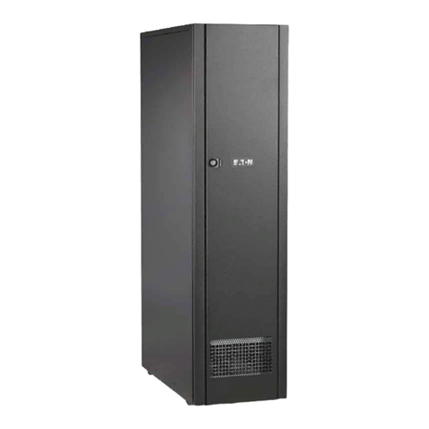
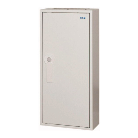
Product Diagram
1
2
3
4
5
6
1. Enclosure base
2. Enclosure cover
3. Keys, locking mechanism, and pin
4. Mounting screw caps
5. Spacer block
6. Cover screws
2. Mount the IQ35M-ENC enclosure to a wall or panel
Extreme care should be taken to protect the equipment from
drill chips, filings, and other contaminants when making
the wire entry holes and mounting the enclosure to prevent
component damage or a future malfunction.
Any holes cut into the enclosure for wire conduit conections
should be cut prior to the installation of the meter in the
enclosure. All holes should be properly sealed to maintain
the enclosure rating.
The IQ35M-ENC base can be installed using either a
2-point or a 4-point screw mounting.
A. Punch out the corner holes for 4-point mounting:
B. Drill out the center holes for 2-point mounting:
3. Install IQ 35M Onto DIN Rail Inside the IQ35M-ENC
Push the top of the IQ 35M onto the DIN rail.
Then push the bottom of the meter onto the DIN rail until
there is an audible click.
Use caps to cover screw
heads after mounting.
