3
Instruction Booklet IB157001EN
Effective May 2015
Fixed capacitor banks (Unipump, Unipak, and Unipak
detuned lter) low voltage (600 V and below), NEMA 1
NEMA 3R (outdoor) enclosed versions
EATON www.eaton.com
Receiving
Check the capacitor bank when receiving to verify that there is no
shipment or handling damage during transit. Minor damage such as
scratches or small dents to the outer enclosure will not inhibit the
capacitor’s performance, but units with large dents or leaks should
not be installed. In case of major damage, file a claim against the
carrier and also notify the nearest Eaton sales office for instructions
regarding the disposition of the capacitor bank.
Check the capacitor’s nameplate to verify that the nameplate voltage
rating matches the system and the applied voltage.
Installation
Install capacitor bank in accordance with all applicable local electrical
standards (NECTNFPA 70, etc.). Failure to properly install capacitor
bank in accordance with local electrical safety standards may cause
electrical shock, fire, and incorrect operation including reduction in
useful life of the capacitor bank.
Preparation for installation
The capacitor bank storage temperature range is –40 °C to +55°C,
and the operating temperature range is –40 °C to +46 °C. For
optimal equipment life, prepare to install the capacitor bank in an
area free of external heat sources, such as direct sunlight.
For optimal equipment life, a harmonic resonance evaluation
should be performed prior to installation, particularly if an unfiltered
capacitor bank is used.
Installation locations
Capacitor banks should be located in a well-ventilated area with a
minimum of 3 inches of clearance around all sides and top of the
enclosure to ensure good air circulation.
Equipment rated for indoor use should be installed indoors in a dry
environment. Outdoor rated units shall be shielded from the radiant
heat of direct sunlight by a canopy or a sunshade.
Both for indoor and outdoor installations, the maximum ambient
temperature should not exceed 40 °C (104 °F) and the annual average
temperature should not exceed 35 °C (95 °F). Higher location ambient
temperatures will cause capacitor failure and reduction in useful life of
the capacitor, including instantaneous failures.
Installation procedures
Mechanical installation
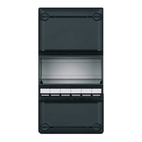
To open the capacitor bank enclosure, remove the screws holding
the top cover. Grasp the front cover and tilt it forward and down to
separate it from the base unit.
Inspect the internal capacitor cells to verify that no physical damage
has occurred during shipment or handling.
Inspect and ensure that the power conductors are secured and tight
in their terminals by applying a gentle tug on the wires on both ends.
Inspect the discharge resistors for any marks of damage or cracks
and that they are seated and intact in the terminal.
If any signs of loose or cracked discharge resistor is noticed, stop
and do not proceed with the installation and immediately notify your
nearest Eaton sales person for further instructions.
Mechanically secure the capacitor bank to either the wall or the floor
using anchor fasteners.
Electrical installation
In accordance with NECT460, conductors should be sized for at
least 135% of the nameplate full load amps of the capacitor unit.
NEC460 also requires that the power factor capacitors must be
provided with a disconnecting means and overcurrent protection.
When connecting the capacitor bank on the load side of a motor
starter overload relay, it is not necessary to provide additional
disconnecting or overcurrent protection devices.
Fuses should be rated at least 165% of rated capacitor current.
A circuit breaker should be rated at least 135% of the rated
capacitor current.
Eaton requires that all customer feeder supply wiring be 90 °C rated
stranded copper wire sized and used at its 75 °C ampacity rating.
Observe all torque requirements for electrical connections. When
making connection using crimp terminals, be sure to use the
crimping tool recommended by the terminal manufacturer. Wire and
cable connections having improper torque may cause loosening of
the electrical connections resulting in localized heating or fire. The
unit should be cleaned of any debris, metal shavings, insulation, and
conductor strippings before being put into service.
An appropriately sized ground conductor should always be
connected to the ground terminal. Lack of ground connection or
improper grounding may result in electric shock or fire or inability
of ground fault protection to operate.
Conduit entry location should be selected so as to allow the
straightest connection to the provided mechanical lugs without
compromising the conductors’ bending radii. Connect the capacitor
bank by securing power conductors into the provided mechanical
lugs and tighten to the torque provided in Table 3. Connect ground
conductor into grounding lug and secure by tightening per torque
requirements below.
Conduit sizes, tray sizes, and cable ampacity must be according
to the National Electrical Code or applicable electrical codes in the
customer’s area.
Proceed to connect the feeder cables to the disconnecting switch/
circuit breaker. This operation must be performed with the
equipment completely de-energized.
Table 3. Recommended torque
Torque based on conductor size Torque based on bolt size
AWG Pound-inch Inches Pound-inch
30–10 80 1/8 45
8 80 5/32 100
6–4 165 3/16 120
3 275 7/32 150
2 275 1/4 200
1 275 5/16 275
1/0–2/0 385 3/8 375
3/0–4/0 500 1/2 500
250–350 650 9/16 600
400 825
500 825
600–750 1000
ote:N Follow the lower torque value between the conductor size
and the bolt size.
