3
2. One Main without Tie Breaker
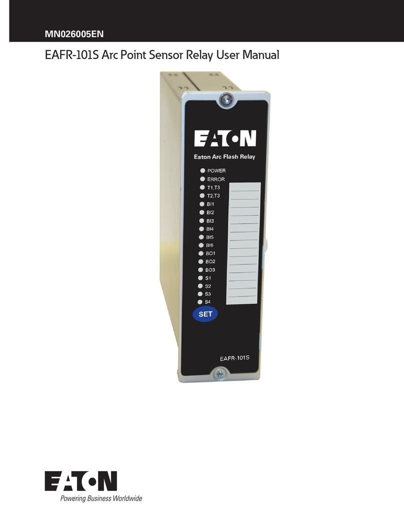
Standard Arc Configurations User Manual for Eaton Arc Flash Relays MN026009EN January 2016 www.eaton.com
Table 1. Configuration Table for Figure 1
Configuration Selection Number EAFR-110P CS:1,A
EAFR-101 CS:1
Number of Incoming Mains 1 x Incoming Main
Number of Outgoing Feeders nx Outgoing Feeders
Number of the Circuit Breakers 1 x Main CBs
n x Outgoing CBs
Selective Trip for Incoming Main CBs Yes
Selective Trip for Outgoing Feeder CBs Yes
Master Trip Function (MT) Yes
Units Applied 1 x EAFR-110P
n x EAFR-101
Note: n = 1 to 20.
2.1.2 Trip and I/O Description
EAFR-110P CS:1,A
Table 2. Trip and I/O Description - EAFR-110P CS:1,A.
Light Current
(Internal)
I/O Description Trip Description
IL, Ig Current inputs phase IL1, IL2, IL3, and E/F Ig.
Measuring current for main(s).
Signal outputs: HSO1 (current) to outgoing units EAFR-101 CS:1 input BI1.
S1 Sensor channel 1.
Monitoring incoming cable compartment.
Trip criteria: Light only.
Trip outputs: T1 (main CB), T2 (upstream CB [HV side]), T4 (trip alarm).
S2 IL, Ig Sensor channel 2.
Monitoring incoming circuit breaker compart-
ment.
Trip criteria: Current + Light.
Trip outputs: T1 (main CB), T2 (upstream CB [HV side]), T3 (not in use), T4 (trip alarm).
Signal outputs: HSO2 (MT) to outgoing units EAFR-101 CS:1 input BI2.
S3/S4 IL, Ig Sensor channel 3/4.
Monitoring busbar compartment.
Trip criteria: Current + Light.
Trip outputs: T1 (main CB), T3 (not in use), T4 (trip alarm).
Signal outputs: HSO2 (MT) to outgoing units EAFR-101 CS:1 input BI2.
BI2 IL, Ig Binary input 2. Trip criteria: Current + Light.
Trip outputs: T1 (main CB), T3 (not in use), T4 (trip alarm).
Signal outputs: HSO2 (MT) to outgoing unit EAFR-101 CS:1 input BI2.
Signal inputs: Light from outgoing units EAFR-101 CS:1 output BO1.
Table 3. Trip and I/O Logic - EAFR-110P CS:1,A.
Inputs Outputs
Light Current (Internal) T1 T2 T3 T4 HSO1 (Current) HSO2 (MT) BO1
IL, Ig x
S1 x x x
S2 IL, Ig x x x x x x
S3 IL, Ig x x x x x
S4 IL, Ig x x x x x
BI2 IL, Ig x x x x x
