Eaton DV2-A10B Operating instructions

Data-Voice-Video 3G Power
Solutions
Installation and Operation Guide
(UL-Listed Models)
Issue:
IPN 997-00012-82B
Issue Date:
May 2011

The product discussed in this literature is subject to terms and conditions outlined in Eaton selling policies. The
sole source governing the rights and remedies of any purchaser of this equipment is the relevant Eaton selling
policy.
No warranties, express or implied, including warranties of fitness for a particular purpose or merchantability, or
warranties arising from course of dealing or usage of trade, are made regarding the information,
recommendations and descriptions contained herein.
In no event will Eaton be responsible to the purchaser or user in contract, in tort (including negligence), strict
liability or otherwise for any special, indirect, incidental or consequential damage or loss whatsoever, including but
not limited to damage or loss of use of equipment, plant or power system, cost of capital, loss of power, additional
expenses in the use of existing power facilities, or claims against the purchaser or user by its customers resulting
from the use of the information, recommendations and descriptions contained herein.
The information contained in this literature is subject to change without notice.
Subject to the right to use its equipment, Eaton Corporation does not convey any right, title or interest in its
intellectual property, including, without limitation, its patents, copyrights and know-how.
No part of this literature may be reproduced or transmitted in any form, by any means or for any purpose other
than the Purchaser’s personal use, without the express written permission of Eaton Corporation.
Eaton®, Matrix, Powerware®, IntergyTM, CellSureTM, SiteSureTM, PowerManagerIITM and DCToolsTM are trade
names, trademarks, and/or service marks of Eaton Corporation or its subsidiaries and affiliates. Unless otherwise
noted, brands, product names, trademarks or registered trademarks are the property of their respective holders.
Copyright © 2011 Eaton Corporation. All Rights Reserved.

About This Guide
Copyright © 2011 Eaton Corporation. All Rights Reserved.
IPN 997-00012-82B May 2011
i
AboutThis Guide
Purpose
This guide provides instructions to correctly install, commission and operate Eaton Data-Voice-
Video 3G Power Solutions (DV2-3G) (UL-Listed Models).
Audience
This guide is intended for use by:
Installers competent in:
installing and commissioning dc power systems
safe working practices for ac and dc powered equipment
the relevant local electrical safety regulations and wiring standards
Operators and maintenance staff competent in:
operation of dc power systems
safe working practices for ac and dc powered equipment
Scope
This guide covers installation, commissioning, operation and maintenance of Eaton Data-Voice-
Video 3G Power Solutions.
It does not cover:
System controller operations; installation of external alarm and user digital inputs cabling;
or setup of communications options or software. For details refer to the system controller
operation handbook listed under Related Information on page i.
Installation and configuration of Eaton SiteSure and CellSure modules. For details, refer to
the relevant guide listed under Related Information on page i.
Related Information
PowerManagerII Online Help
DCTools Online Help
SC200 System Controller Operation Handbook –IPN 997-00012-50
SiteSure-3G Installation and Operation Guide –IPN 997-00012-51
CellSure Installation Guide –IPN 997-00012-20
Reporting Problems with this Guide
Please use this email address to report any problems you find in this guide:
Eaton DC Product Marketing Communications

Table of Contents
Copyright © 2011 Eaton Corporation. All Rights Reserved.
IPN 997-00012-82B May 2011
iii
Tableof Contents
About This Guide
Purpose....................................................................................................................................... i
Audience..................................................................................................................................... i
Scope ........................................................................................................................................... i
Related Information .................................................................................................................. i
Reporting Problems with this Guide...................................................................................... i
For Further Information and Technical Assistance ............................................................. ii
Chapter 1 General Description
Overview ................................................................................................................................... 1
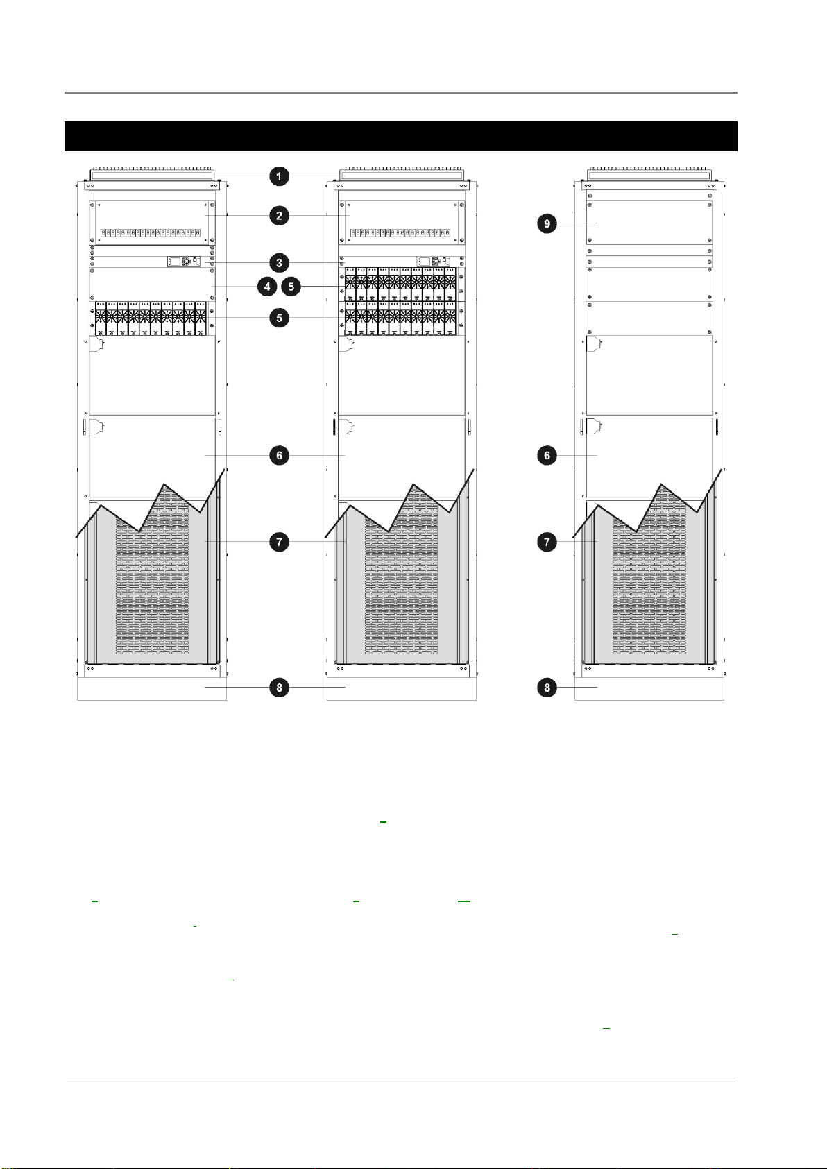
DC Power Systems................................................................................................................... 2
Rectifiers .................................................................................................................................... 3
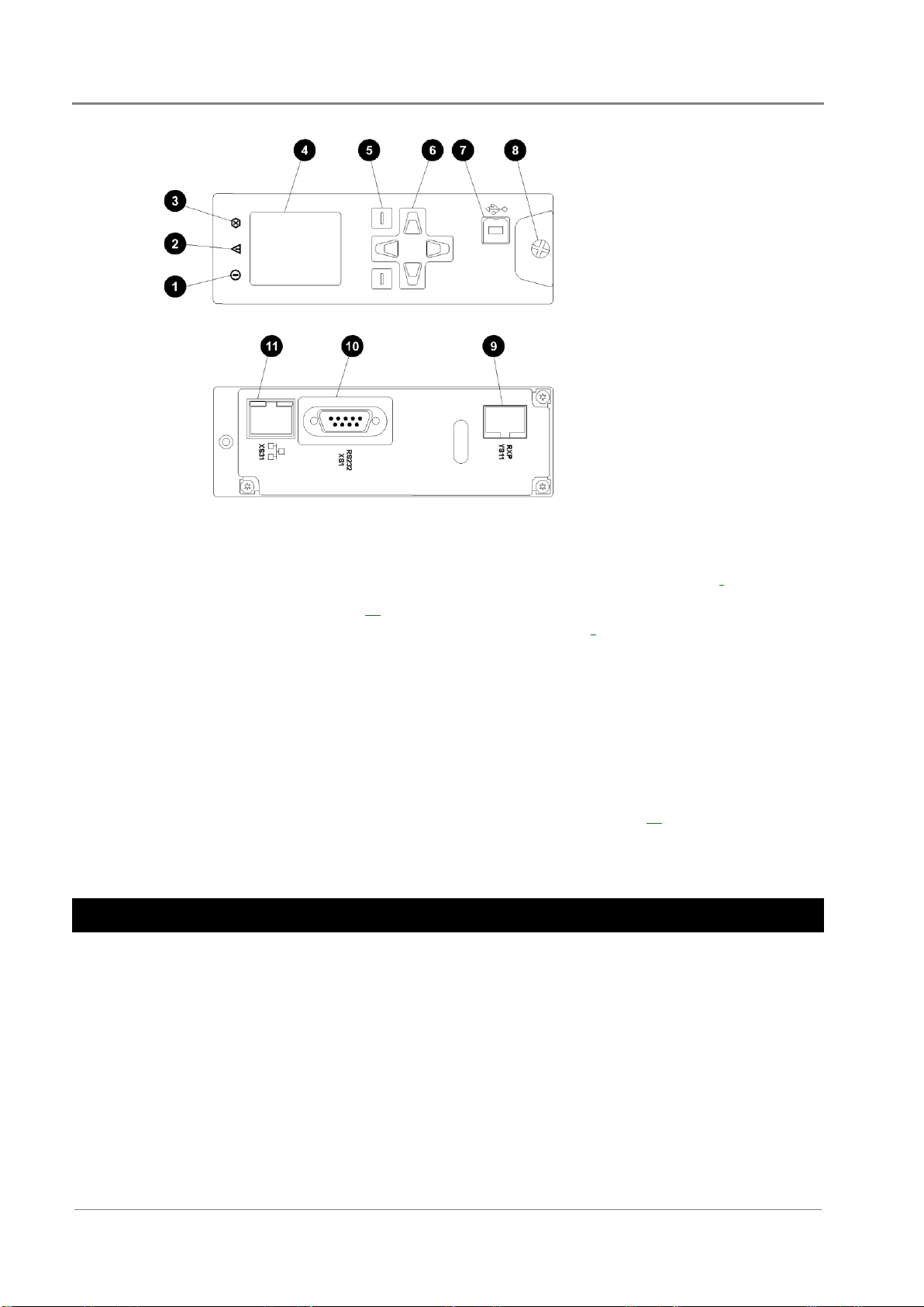
SC200 System Controller......................................................................................................... 3
Compatible Software....................................................................................................................... 4
Input/Output Board................................................................................................................ 4
Connections...................................................................................................................................... 6
Other Features .......................................................................................................................... 7
External communications............................................................................................................... 7
Low Voltage Disconnect (LVD) option......................................................................................... 7
Additional DC Distribution Module............................................................................................. 7
Battery Mid-point Monitoring Description.................................................................................. 8
Reverse Battery Detect Option....................................................................................................... 8
Bottom Cable Entry Option............................................................................................................ 8
Chapter 2 Preparation
Overview ................................................................................................................................... 9
Warnings ................................................................................................................................. 10
Inspecting the Equipment and Reporting Damage ........................................................... 12
Chapter 3 Positioning Cabinets
Overview ................................................................................................................................. 13
Preparation.............................................................................................................................. 14
Fixing Cabinets ....................................................................................................................... 14
Mounting ........................................................................................................................................ 14
Cabinet Footprint........................................................................................................................... 15
Fit the Rear Extension Cabinet (if required) ....................................................................... 15
Chapter 4 DC Cabling
Overview ................................................................................................................................. 17
DC Installation Practices ....................................................................................................... 18
Connecting the Telecom Earth Cable .................................................................................. 18
Fit or Remove Low Voltage Disconnects ............................................................................ 19
Load Cables and Circuit Breakers........................................................................................ 22
Fit DCM2000 in Battery Cabinet (if required) .................................................................... 25
Chapter 5 Battery Installation
Overview ................................................................................................................................. 27
Battery Types .......................................................................................................................... 28
Installing the Batteries ........................................................................................................... 28
Install the Batteries ........................................................................................................................ 29
Battery Cable Links for Additional Battery Racks (if required) .............................................. 31
Installation procedure................................................................................................................... 31

Data-Voice-Video 3G Power Solutions (UL-Listed Models)
iv
Copyright © 2011 Eaton Corporation. All Rights Reserved.
IPN 997-00012-82B May 2011
Chapter 6 AC Cables
Overview..................................................................................................................................33
Input Transient Protection.....................................................................................................34
Connecting to the AC Supply................................................................................................37
Connecting the Output to Earth............................................................................................40
Chapter 7 Start-Up
Overview..................................................................................................................................43
Start-Up Tasks .........................................................................................................................44
Task 1 - Inserting the Rectifiers .............................................................................................44
Task 2 - Pre-Power-Up Checklist ..........................................................................................45
Task 3 - Applying AC Power.................................................................................................45
Task 4 - Configure the dc power system..............................................................................46
Task 5 - Apply DC Power to Battery and Load ..................................................................47
Start-Up Completed................................................................................................................48
Chapter 8 Maintenance
Overview..................................................................................................................................49
Troubleshooting ......................................................................................................................50
Replacing or Adding a Rectifier............................................................................................54
Replacing or Adding a Circuit Breaker................................................................................55
Replacing the System Controller...........................................................................................55
Replacing the Input/Output Board......................................................................................58
Battery Mid-point Monitoring (String Fail) Alarm.............................................................59
Battery Disposal and Recycling ............................................................................................60
Appendix A Equipment and Tools
Safety Equipment...........................................................................................................................61
Essential Tools................................................................................................................................61
Recommended Tools .....................................................................................................................61
Spare Parts ...............................................................................................................................62
Parts for DCM2000 Circuit Breaker Distributions .....................................................................63
Battery Circuit Breakers ................................................................................................................63
Purchasing Information ................................................................................................................64
Standard Torque Settings.......................................................................................................64
Appendix B Specifications
Appendix C Connector Pin-outs
System Controller Connector Pin-outs ................................................................................69
I/O Board (IOBGP-00, -01) Connector Pin-outs .................................................................71
Appendix D System Wiring Diagrams
Appendix E Checklists
Equipment Incident Report
Worldwide Support
Index

Data-Voice-Video 3G Power Solutions (UL-Listed Models)
2
Copyright © 2011 Eaton Corporation. All Rights Reserved.
IPN 997-00012-82B May 2011
DC Power Systems
DV2-A10B Model
Up to 10 rectifiers
24V or 48V
DV2-A20B Model
Up to 20 rectifiers
48V only
DV2-EBC4
Extension Battery
Cabinet
Top cable entry* and ac terminations. See details on page 8
for optional bottom cable entry.
DCM2000 20-way dc circuit breaker distribution module.
Alarm signal if circuit breaker is electrically tripped only.
Input/Output (I/O) board (behind panel) (see details on page
4) and SC200 system controller (see details on page 3). (Also
refer to the system controller handbook listed in Related
Information on page i.)
3U space for other equipment (DV2-A10B models only).
Rectifier magazine for up to 10 rectifiers per magazine. See
details of rectifiers on page 3.
Four battery shelves (7.5U high) with battery circuit breakers.
Alarm signal if circuit breaker is electrically tripped or switched
off.
Battery shelf front cover.
Optional plinth for use with raised floors. See part number on
page 62.
4U space for optional second DCM2000 20-way dc circuit
breaker distribution module. See details on page 7.
A full-height security door (not shown) is supplied with all
cabinets.
* A Bottom Cable Entry Duct is available as an option. See details on page 8.

General Description
Copyright © 2011 Eaton Corporation. All Rights Reserved.
IPN 997-00012-82B May 2011
3
Rectifiers
Data-Voice-Video 3G Power Solutions are fitted with either 48V, 2000W (APR48-ES); 48V,
1800W (APR48-3G); or 24V, 1440W (APR24-3G) rectifiers. The rectifiers are fan-cooled and hot-
pluggable.
See Specifications on page 65 for further information. See Troubleshooting on page 50 for details of
rectifier alarms.
Left: APR24-3G and APR48-3G
Right: APR48-ES
Power On LED (Green)
Minor Alarm LED (Yellow)
Major Alarm LED (Red)
Serial Number
Retaining Screw. Tighten to 1.5Nm
(13.3 inch-pounds).
SC200 System Controller
The SC200 system controller is an advanced control and monitoring solution which provides a
full suite of communications options, including built-in Ethernet interface, Web server, and
SNMP agent.
Alarm notifications may be by SNMP traps, SMS text messaging, dial-out to PowerManagerII
remote monitoring software, or relay contact closures.

Data-Voice-Video 3G Power Solutions (UL-Listed Models)
4
Copyright © 2011 Eaton Corporation. All Rights Reserved.
IPN 997-00012-82B May 2011
Power on LED (green)
Minor alarm LED (yellow)
Critical/Major alarm LED (red)
Color LCD
Soft keys (2)
Navigation keys (4)
USB 1.1 connector (12Mb/s)
Retaining screw
Power and system
communications connector
RS232 connector
Ethernet connector and
status LEDs
The SC200 is supplied pre-configured with either a default configuration file, or with one
factory customized for a particular application. Some configuration file changes can be made
with the keypad, or all settings can be changed via a PC connected to the USB interface. For
details refer to the SC200 Operation Handbook (see Related Information on page i).
See Troubleshooting on page 50 for details of SC200 alarms. For connector pin-outs refer to the
SC200 Operation Handbook (see Related Information on page i).
Compatible Software
The following software is compatible with the SC200 system controller:
DCTools Configuration Software. Latest version is available free from
www.powerquality.eaton.com/downloads.
PowerManagerII Remote Control and Monitoring Software. Contact your Eaton dc product
supplier for further information (see Worldwide Support on page 85).
Recommended web browsers: Microsoft Internet Explorer 8 (IE6 is compatible but with
reduced performance), Mozilla Firefox 3.0.
Input/Output Board
The input/output (I/O) board provides the I/O interfaces and connections for the SC200
system controller.
The I/O board includes a range of sense inputs for dc power system control and monitoring. It
also allows real time data collection from building services and other external devices, and relay
outputs for alarm signals or control of external devices.

General Description
Copyright © 2011 Eaton Corporation. All Rights Reserved.
IPN 997-00012-82B May 2011
5
The I/O functions are:
Sensors:
Current - 3, Bus voltage - 1, Temperature - 2, Battery Mid-point - 4
Input/Output:
Digital inputs: 4 pre-defined system functions, 6 user-defined
Relay outputs: 6 (one also used as Monitor OK alarm)
LVD contactor outputs: 2
For input and output specifications see details on page 67. For connector pin-outs see details on
page 71.
Bus voltage sense input - XH9
Power/Comms OK LED (green)
Digital inputs D1-D6 (6 user defined) - XH15A,
XH15B
Digital (relay) outputs RY1-RY6 (6) - XH16-XH21
LVD contactor 2 status LED (green)
LVD contactor 2 connector - XH5
LVD contactor 1 status LED (green)
LVD contactor 1 connector - XH4
LVD power input connector - XH8
Power and RXP comms input - YH11
Current sense inputs (3) - XH6
Temperature sense inputs (2) - XH7
Battery Mid-point Monitoring sense inputs - XH12
DC power system digital inputs (4 pre-defined:
Load Fuse Fail, Battery Fuse Fail, AC Distribution
Fan Fail, AC Distribution MOV Fail) - YH3
See Troubleshooting on page 50 for details of I/O board LED signals.

Data-Voice-Video 3G Power Solutions (UL-Listed Models)
6
Copyright © 2011 Eaton Corporation. All Rights Reserved.
IPN 997-00012-82B May 2011
Connections
The following diagram shows the connections between the SC200, the I/O board, the other dc
power system components and external devices.
SC200 system controller
I/O board
Voltage feed module
USB communications
Ethernet communications
RS232 communications
Digital relay outputs (6) to external devices and/or
alarm indication system
Digital inputs (6) from external voltage-free
switches or relay contacts
Connection to additional I/O board(s) and/or
SiteSure-3G I/O module(s) via RJ45 splitter (see
details)
Connection to dc common bus
Connection to dc live bus
Communications to rectifiers
DC power system digital inputs (Load Fuse Fail,
Battery Fuse Fail, AC Distribution Fan Fail, AC
Distribution MOV Fail)
Connections to battery mid-points (4)
Connection to temperature sensors (2)
Connection to current sensors (3)
Optional LVD contactor and auxiliary switch (see
details on page 7)
Optional LVD contactor and auxiliary switch (see
details on page 7)
Bus voltage sense and LVD power connections
I/O and system controller power and RXP comms
connections
For connector pin-outs see details on page 71. For input and output specifications see details on
page 65.

General Description
Copyright © 2011 Eaton Corporation. All Rights Reserved.
IPN 997-00012-82B May 2011
7
Other Features
External communications
Refer to the SC200 system controller handbook for information on these communications
options:
Communication with DCTools via USB
Communication with DCTools or PowerManagerII via RS232
Communication with DCTools or PowerManagerII via an external PSTN or GSM modem
(dial-in and dial-out on alarm)
Communication with DCTools or PowerManagerII via Ethernet
Communication with any web browser software via an IP network
Communication with a Network Management System (NMS) using SNMP
Communication with a Building Management System (BMS) using Modbus
Alarm and status messages to GSM Short Messaging Service (SMS) text capable cell phones
Communication with an alarm management system using voltage-free relay contacts (on
an IOBGP I/O board).
Low Voltage Disconnect (LVD) option
Data-Voice-Video 3G Power Solutions may be fitted with one or two Low Voltage Disconnects
(LVDs). The LVD(s) are connected to disconnect the low-priority loads (LVD 1) and to
disconnect the battery (LVD 2).
LVDs have two purposes:
to protect a VRLA battery from deep discharge and premature failure, and/or
to reduce the load on a battery under discharge so that high priority equipment operates
for a longer time after an ac supply failure.
The two LVD control channels (LVD 1 and LVD 2) can be set to disconnect at specified voltages
or can be set to disconnect a specified time interval after an ac supply failure. Both channels
reconnect the battery or load equipment when the ac supply is restored.
Refer to the system controller handbook (see Related Information on page i) for information on
how to configure the LVD channels.
Refer to Fit or Remove Low Voltage Disconnects on page 19 for further details. See also
Specifications.
Additional DC Distribution Module
An optional second DCM2000 dc distribution module can be installed in the extension battery
cabinet. See Parts List on page 62.
This dc distribution module can have either a single or dual feed from the DCM2000 in the dc
power system cabinet.
For details of how to fit the DCM2000 dc distribution module , see details on page 25.

Data-Voice-Video 3G Power Solutions (UL-Listed Models)
8
Copyright © 2011 Eaton Corporation. All Rights Reserved.
IPN 997-00012-82B May 2011
Battery Mid-point Monitoring Description
Battery Mid-point Monitoring provides a cost-effective method for the early detection of
internal battery faults. The voltages of the two halves of a battery string are measured and the
system controller generates an alarm signal if a voltage imbalance is detected.
A voltage imbalance is an indication that one or more cells has an internal fault. Further
investigation can then isolate the faulty cell(s) and action can be taken to correct the problem
and prevent a total battery failure.
To connect Battery Mid-point Monitoring see details on page 29. If a String Fail alarm is
generated see Troubleshooting on page 50.
To ensure reliable operation Mid-point Monitoring operates only when the battery is in float
charge and after a configurable lockout period since the last battery discharge, Fast Charge,
Equalize or Battery Test.
Reverse Battery Detect Option
Reverse Battery Detection detects if a battery has been connected with the incorrect polarity.
Bottom Cable Entry Option
A rear extension cabinet is available for bottom cable entry. See Parts List on page 62.
For details of how to fit the rear extension cabinet, refer to Fit the Rear Extension Cabinet on
page 15.

Data-Voice-Video 3G Power Solutions (UL-Listed Models)
10
Copyright © 2011 Eaton Corporation. All Rights Reserved.
IPN 997-00012-82B May 2011
Warnings
This section contains important warnings. Read these warnings before installing or operating
Data-Voice-Video 3G Power Solutions dc power systems.
Electrical Safety
The cabinet of the Data-Voice-Video 3G Power Solutions (UL-Listed Models) dc power system is a fire
enclosure as specified in UL 60950-1.
All power sources must be isolated before internally servicing the equipment.
The dc power system must be connected to a suitable and readily accessible disconnect device(s).
The dc power system is not compatible with IT (Impedance Terra) ac supply. For advice see Worldwide
Support on page 85.
A registered electrician (or suitably qualified person) must check the integrity of the installed cabling,
BEFORE the dc power system is powered up.
Tasks must be performed in the sequence documented in this guide.
Location and Environment
The DV2-3G must be installed in a Restricted Access Location (dedicated equipment rooms, equipment
closets, or similar) in accordance with the U.S. National Electric Code (NEC), ANSI/NFPA No. 70, and
according to the applicable local codes.
For ease of access and to maintain optimum system cooling, observe the clearances stated on page 14.
Ensure the ambient temperature and humidity are within the ranges in the Specifications on page 66.
Dust build-up within the DV2-3G may cause premature failure. In dusty environments filter the
ventilation air entering the equipment room. Ensure regular cleaning of the air filters.
Do not allow water or any foreign object to enter the DV2-3G. Do not place objects containing liquid on
top of or near the unit.
Reverse Polarity
Always check that the battery cables have been terminated to the correct system polarity BEFORE
connecting the batteries or closing the battery disconnect device. Connecting batteries to the dc power
system with incorrect system polarity will damage the rectifiers and void all warranty claims.
Hazardous Energy Levels
Rectifiers and batteries contain hazardous energy levels. Only personnel trained and experienced in dc
power systems are to service/maintain this equipment.
Always use insulated tools.
Do not short-circuit the live and common bus bars or cables.
Maximum Load Currents
Do not exceed the maximum load currents stated in the Specifications on page 65.
Battery Current
The short circuit current capability of the battery circuit connected to the battery input terminals must not
exceed 5,000A.

Preparation
Copyright © 2011 Eaton Corporation. All Rights Reserved.
IPN 997-00012-82B May 2011
11
Batteries
Flooded cell and VRLA lead acid batteries can emit explosive gases and must be installed with adequate
ventilation. Refer to the battery manufacturer or supplier for advice on minimum ventilation levels.
Do not wear a synthetic dust-coat or overalls. Synthetic fabrics can hold static electric charges that create
sparks during discharge.
Remove rings, wristwatch and other metal jewelry that might be exposed to battery terminals, before
installing batteries.
Batteries are powerful sources of energy and present a potential electrical shock and energy hazard. The
energy hazard is always present, even if the batteries are not connected. Avoid short circuiting terminals
of opposite polarity.
Always use insulated tools.
Do not place tools, loose cables or metal objects (such as interconnecting bars) on top of batteries.
Do not drop tools, loose cables or metal objects onto intercell connections or terminals of opposite
polarity.
Only terminate cables and interconnecting bars after confirming that the termination will not create a
short circuit.
Always tighten battery terminal bolts according to the battery manufacturer’s specification. Failing to do
so can cause erratic battery performance, possible damage to the battery, and/or personal injury.
There is a risk of electric shock or explosion if a battery is replaced by an incorrect type.
Dispose of batteries according to the instructions on page 60.
Rectifiers
Do not install the rectifiers until the room has been cleaned and is dust free.
To reduce the risk of electric shock and maintain optimum system cooling, always cover empty rectifier
slots with blanking panels.
To avoid electrical shock, do not place hands inside the rectifier magazine.
Rectifier cases may exceed 100ºC (212ºF), especially after prolonged operation. Use suitable gloves when
removing a rectifier from the magazine.
Do not attempt to disassemble faulty rectifiers. Return them (in their original packaging) with a
completed Equipment Incident Report on page 83.
Servicing and Maintenance
The DV2-3G contains hazardous voltages and hazardous energy levels. Before undertaking any
maintenance task refer to the Warnings on page 10.
If a maintenance task must be performed on a "live" system then take all necessary precautions to avoid
short-circuits or disconnection of the load equipment, and follow any "live-working" instructions
applicable to the site.
Only perform the maintenance tasks described in the Maintenance chapter. All other tasks are classified
as Servicing. Servicing must only be performed according to specific instructions and only by personnel
authorized by Eaton. This includes disassembly and/or servicing of any modules.
For further information on Servicing contact your local Eaton dc product supplier, or refer to the contact
details on page 85.

Data-Voice-Video 3G Power Solutions (UL-Listed Models)
12
Copyright © 2011 Eaton Corporation. All Rights Reserved.
IPN 997-00012-82B May 2011
Telecom Ground and dc Supply Bond to Chassis
CAUTION: This equipment has a connection between the earthed conductor of the dc supply circuit and
the earthing conductor.
Cet appareil comporte une connexion entre le conducteur relié à la terre du circuit d'alimentation c.c. et son
conducteur de terre.
All of the following installation conditions must be met:
This equipment shall be connected directly to the dc supply system earthing electrode conductor or
to a bonding jumper from an earthing terminal bar or bus to which the dc supply system earthing
electrode conductor is connected.
This equipment shall be located in the same immediate area (such as adjacent cabinets) as any other
equipment that has a connection between the earthed conductor of the same dc supply circuit and
the earthing conductor, and also the point of earthing of the dc system. The dc system shall not be
earthed elsewhere.
The dc supply source shall be located within the same premises as this equipment.
Switching or disconnecting devices shall not be in the earthed circuit conductor between the dc
source and the point of the connection of the earthing electrode conductor.
Ce matériel doit être raccordé directement au conducteur de la prise de terre du circuit d'alimentation c.c. ou à une
tresse de mise à la masse reliée à une barre omnibus de terre laquelle est raccordée à l'électrode de terre du circuit
d'alimentation c.c. Les appareils dont les conducteurs de terre respectifs sont raccordés au conducteur de terre du
même circuit d'alimentation c.c. doivent être installés à proximité les uns des autres (p.ex., dans des armoires
adjacentes) et à proximité de la prise de terre du circuit d'alimentation c.c. Le circuit d'alimentation c.c. ne doit
comporter aucune autre prise de terre. La source d'alimentation du circuit c.c. doit être située dans la même pièce
que le matériel. Il ne doit y avoir aucun dispositif de commutation ou de sectionnement entre le point de
raccordement au conducteur de la source d'alimentation c.c. et le point de raccordement à la prise de terre.
EMC Compliance
This Eaton product ("the equipment") has been tested and found to comply with the limits for a Class A
digital device, pursuant to part 15 of the Federal Communications Commission (FCC) Rules. These limits
are designed to provide reasonable protection against harmful interference when the equipment is
operated in a commercial environment.
The equipment generates, uses, and can radiate radio frequency energy and, if not installed and used in
accordance with the instructions in this installation guide, may cause harmful interference to radio
communications.
Operation of this equipment in a residential area is likely to cause harmful interference in which case the
user will be required to correct the interference at his own expense.
Changes or modifications to the equipment not approved by Eaton Corporation could void the FCC
authority to operate the equipment.
Inspecting the Equipment and Reporting Damage
Unpack the equipment and inspect it carefully for possible damage that may have occurred
while in transit. Do not use any damaged equipment.
Report any damage immediately, using a completed Equipment Incident Report on page 83.
Keep the original packaging to use if any item needs to be returned for replacement or repair.

Data-Voice-Video 3G Power Solutions (UL-Listed Models)
14
Copyright © 2011 Eaton Corporation. All Rights Reserved.
IPN 997-00012-82B May 2011
Preparation
Before installation ensure that:
The floor surface where the equipment is to be installed is level.
The floor surface where the equipment is to be installed, and any areas over which the
equipment must be moved, are sufficiently strong to take the weight of the cabinets and the
point loading of the transport mechanism.
The mass of cabinets is given in Dimensions.
All areas of floor are protected from damage by the transport of the equipment. Use
hardboard or a similar material. This material must be removed once installation is
complete.
The installation area is clean and dry.
Positioning
In locating the equipment, the following must be considered:
Allow for working space in front of the system and for opening the security door
(minimum 24"/610mm).
Allow for working space behind the system (minimum 24"/600mm).
Allow space at one end for access to the space behind the system.
Allow distances from other equipment as required by the installation requirements of that
equipment.
When installing on a raised "computer floor", locate the first cabinet over one tile. If load
spreading is required due to cabinet weight then this must be installed prior to cabinets
being installed.
Fixing Cabinets
Mounting
The Data-Voice-Video 3G Power Solutions cabinets are mounted directly to the floor. The
method of fixing must be suitable for the cabinet size and weight, and for the surface to which
the cabinet is being secured.
Recommended procedure:
1 Place cabinet in position and align to other cabinets.
2 Mark fixing holes in base of cabinet with permanent marker.
3 Remove cabinet.
4 Drill all marked holes. De-burr all holes.
5 Place cabinets back in position.
6 Fix cabinet using appropriate floor anchors to secure the cabinets.
This manual suits for next models
2
Table of contents
Other Eaton Portable Generator manuals
Popular Portable Generator manuals by other brands

Craftsman
Craftsman 919.67937 owner's manual

ESAB
ESAB ESP-400C Installation, operation and maintenance

Matsusada Precision
Matsusada Precision REK Series instruction manual

BE
BE BE9400DFS user manual

Generac Portable Products
Generac Portable Products PowerBoss 5500 Watt Storm Plus owner's manual

Segway
Segway CUBE-1000 user manual