7
Good oils are the most economical. Specifications can be set
up which will indicate, to a limited degree, the characteristics
essential in a good hydraulic oil. These are listed herein and
should be checked with the oil manufacturer prior to the use of
this product.
2. Viscosity - Viscosity is the measure of fluidity. The oil
must have sufficient body to provide adequate sealing effect
between working parts of pumps, valving, cylinders, etc., but
not enough to cause pump intake cavitation, sluggish valve
action, or in extreme cases, resistance to flow. Viscosity rec-
ommendations must at best be a compromise, which takes
into consideration the working temperature range, the type of
hydraulic equipment used, and the class of service. Refer to
table of oil viscosity recommendations below.
3. Viscosity Index - The viscosity index is a measure of
the rate at which temperature changes cause a change in oil
viscosity. It is very desirable that the oil viscosity remain as
nearly constant as possible under the wide range of temper-
ature conditions encountered in operating mobile and
construction machinery. The viscosity index (V.I.) of hydraulic
oil should not be less that 90 for this type of service.
4. Additives - Research has developed a number of
additive agents which materially improve various characteris-
tics of oils for hydraulic systems. They may be selected for
compounding with a view toward reducing wear, increasing
chemical stability, inhibiting corrosion, depressing pour point
and improving the anti-foam characteristics. Proper use of
additive agents requires specialized knowledge, and they
should be incorporated by the oil manufacturer only, as
serious trouble may otherwise result.
Most oil companies have several brands of crankcase oils of
somewhat varying formulation that will meet the API service
classification of MS. The more desirable of these oils for
hydraulic service will contain higher amounts of the type of
compounding that avoids scuffing and wear of cam lobes
and valve lifters. These oils will also be formulated to be
stable under oxidative conditions and when in contact with
small amounts of moisture. There should also be reasonable
protection against rust to any ferrous materials submerged in
the oil or covered by the oil’s film.
5. Cleanliness - Thorough precautions should be taken to
filter the oil in the entire hydraulic system prior to its initial use
to remove paint, metal chips, welding shot, lint, etc. If this is
not done, damage to the hydraulic system will probably result.
In addition, continuing filtration is required to remove sludge
and products of wear and corrosion, throughout the life of the
system.
Precautions should be taken in the design of hydraulic
circuits to assure that a means is provided to keep the oil
clean. This can best be accomplished by the use of a 25
micron full-flow filter or a 10 micron by-pass filter (not a
strainer) and a micronic air breather or sealed reservoir.
6. Pump Inlet Conditions - Use of an improper grade of
oil or restrictive inlet piping may result in inlet vacuum condi-
tions exceeding the recommended maximum 5 inches of
mercury, and will reduce the life expectancy of the hydraulic
equipment. Where vacuum exceeds 5 inches of mercury,
and it is not caused by improper oil selection, Vickers is to
be consulted.
7. Operating Temperatures - Operation in excess of
180°F. results in increased wear of the system components
and causes more rapid deterioration of the oil. The hydraulic
system that is designed to maintain a temperature of 160° F.
or less desirable.
8. Grade - Table 3 summarizes the oil types (viscosity
and service classification) that are recommended for use
with Vickers equipment. This selection is most important and
should be made with considerable care.
Hydraulic System
Operating Range
(Min. to Max.) SAE
Viscosity API Service
Classification
0°F. to 180°F.
15°F. to 210°F.
32°F. to 230°F.
0°F. to 210°F.
10W
20-20W
30
10W-30
MS
MS
MS
MS
Table 3.
These temperature ranges for each grade of oil are
satisfactory if suitable procedures are followed for low
temperature start-up conditions and if sustained operation is
avoided at the upper temperature limits. For optimum
operation, a maximum oil viscosity of 4000 SSU at low
temperature start-up condition and a minimum oil viscosity of
60 SSU for sustained high temperature operating condition
are recommended. Operation of the fluid at temperatures
below 160°F. is recommended to obtain the maximum unit
and fluid life.
Automatic Transmission Fluid, Type “A”is usually satisfactory
for power steering systems or those systems operating under
moderate hydraulic service.
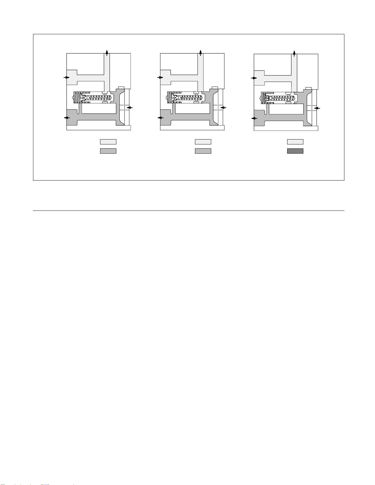
E. Overload Protection
1. An integral relief valve protects the hydraulic system
components by limiting the maximum pressure.
2. Relief valve sub-assemblies are pre-set and tested by
Vickers for given pressure settings. Selection of the correct
setting should be based on the system work requirements. If
the relief setting must be changed, a replacement valve
should be installed.