107-B00 Page 7/12
MAINTENANCE
VANE REPLACEMENT
NOTICE:
Maintenance shall be performed by qualified technicians
only. Following the appropriate procedures and
warnings as presented in manual.
1. Flush the pump per instructions in this manual. Drain and
relieve pressure from the pump and system as required.
2. Remove the head assembly from the outboard
(nondriven) side of the pump according to steps 4 - 8 in
the "Pump Disassembly" section of this manual.
3. Turn the shaft by hand until a vane comes to the top (12
o'clock) position of the rotor. Remove the vane.
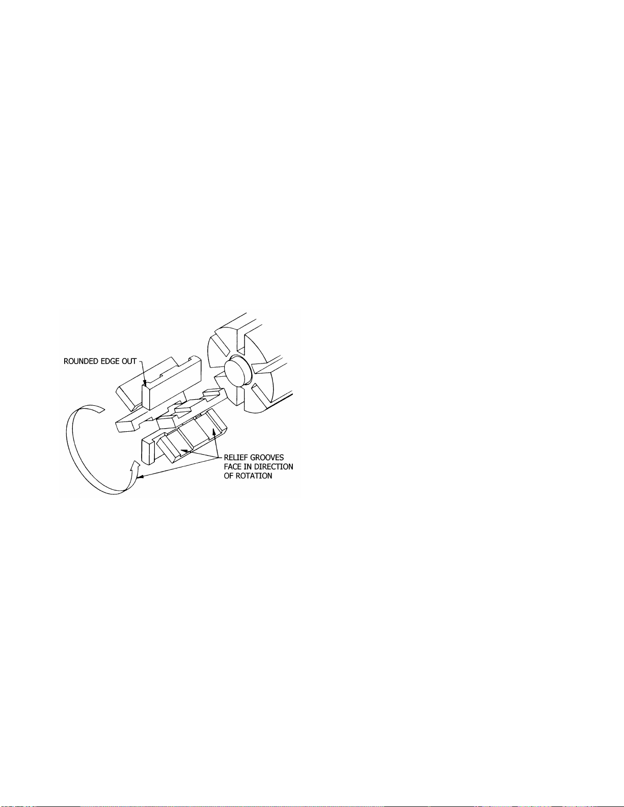
4. Install a new vane, ensuring that the rounded edge is UP,
and the relief grooves are facing towards the direction of
rotation. See Figure 4.
5. Repeat steps 3 and 4 until all vanes have been replaced.
This method of vane installation ensures the push rods do
not fall out of their rotor slots.
6. Reassemble the pump according to the "Pump
Assembly." section of this manual.
Figure 4 – Vane Replacement
PUMP DISASSEMBLY
NOTICE:
Follow all hazard warnings and instructions provided in
the “maintenance” section of this manual.
NOTE: The numbers in parentheses following individual parts
indicate reference numbers on the Pump Parts List.
1. Flush the pump per instructions in this manual. Drain and
relieve pressure from the pump and system as required.
2. Starting on the inboard (driven) end of the pump, clean
the pump shaft thoroughly, making sure the shaft is free
of nicks and burrs. This will prevent damage to the
mechanical seal when the inboard head assembly is
removed.
3. Remove the inboard bearing cover capscrews (28) and
slide the inboard bearing cover (27A) and gasket (26) off
the shaft. Discard the bearing cover gasket. On 2-inch
pump models, the dirt shield will slide off with the bearing
cover.
4. Remove the outboard bearing cover capscrews (28) and
slide the outboard bearing cover (27) and gasket (26) off
the shaft. Discard the bearing cover gasket.
5. To remove locknuts and lockwashers (24A and 24B):
a. Bend up the engaged lockwasher tang and rotate the
locknut counterclockwise to remove it from the shaft.
b. Slide the lockwasher off the shaft. Inspect the
lockwasher for damage and replace as required.
c. Repeat steps a and b on the opposite shaft end.
6. Remove the head capscrews (21). Gently pry the head
away from the casing using two large screwdrivers. The
head O-ring should come off with the head assembly.
7. Slide the head and O-ring off the shaft. The bearing (24),
mechanical seal stationary seat and stationary O-ring
(153A & 153D) will come off with the head assembly.
a. On 4-inch models, remove the disc from the head by
removing the disc machine screws (71A) and
lockwashers (71B). The mechanical seal rotating
assembly (153B, 153C, 153E) will be released when
the disc is removed.
b. Pull the bearing (24) from the housing in the head.
c. To remove the mechanical seal stationary seat
(153A), use the blunt end of a screw driver to gently
push the backside of the stationary seat from the
head. Place a cloth under the seal to avoid damage.
Be careful not to contact the polished face of the seal
during removal. Remove and discard mechanical seal
stationary O-ring.
8. On 2 and 3-inch models, carefully pull the rotating seal
assembly, including seal jacket (153C), rotating seal face
and rotating O-ring (153B & 153E) from the shaft.
Remove and discard the rotating O-ring. Remove the disc
(71).
9. Pull the rotor and shaft (13) from the casing. While one
hand is pulling the shaft, the other hand should be
cupped underneath the rotor to prevent the vanes (14)
and pushrods (77) from falling out. Carefully set the rotor
and shaft aside for future vane replacement and
reassembly.
10. Lay the pump flat with the remaining head facing upward
to remove the outboard head assembly, mechanical seal
and disc from the outboard side of the pump, as
instructed in steps 6 - 8.
11. If necessary, remove the liner (41) by tapping around the
outside diameter of the liner with a hard wood drift and a
hammer until it is driven from the casing.
PARTS REPLACEMENT
1. If any of the O-rings have been removed or disturbed
during disassembly, they be replaced with new O-rings.
NOTE: PTFE O-rings should be heated in hot water to aid
installation.
2. Excessive or continuous leakage from the tell-tale hole in
the bearing cover may be an indication of a damaged
mechanical seal. If a mechanical seal has been leaking, it
is recommended the entire seal be replaced. Refer to
"General Pump Troubleshooting" for possible causes of
seal leakage.