Titan WindMaster 2010 User manual

TITAN Technologies International, Inc.®
9001 Jameel Street, Suite 180 • Houston, TX 77040
http://www.titanti.com
Operating Manual
TITAN®WindMaster™2010
Hydraulic Tensioning Pump

TITAN Technologies International, Inc.®
9001 Jameel Street, Suite 180 • Houston, TX 77040
http://www.titanti.com
Contents
Contents ...........................................................................................2
Signs and symbols ...........................................................................3
Before starting ..................................................................................4
Starting .............................................................................................5
Pressure adjustment.........................................................................6
Venting .............................................................................................7
Coupling of the high-pressure hoses................................................7
Safety hints.......................................................................................9
Short guidance ...............................................................................10
Maintenance...................................................................................11
Operational disturbances and their recovery..................................12
Technical data................................................................................12
Hydraulic-schematic.......................................................................15
Electric-schematic ..........................................................................16
Appendix.........................................................................................17

TITAN Technologies International, Inc.®
9001 Jameel Street, Suite 180 • Houston, TX 77040
http://www.titanti.com
Signs and symbols
Attention!
Attention: Slipping Hazard!
Attention: Overhead Hazard!
Command: High Importance!
Command: Wear protective eye wear with
side shields or safety goggles!
Command: Wear hard toe shoes!
Forbidden!

TITAN Technologies International, Inc.®
9001 Jameel Street, Suite 180 • Houston, TX 77040
http://www.titanti.com
Before starting
These operating instructions is designed to give you some information about the
handling and safe application of theTITAN®WindMaster™ Hydraulic Tensioner
Pump.
Please read these operating instructions carefully to ensure the optimum function
and a high degree of safety.
The equipment is delivered fully assembled, functionally tested, vented and filled with
hydraulic oil. To prevent the oil from spilling during transport, the filling and venting
opening (depending on the model) is sealed with a plug.
Please ensure that it is replaced by the venting screw before commissioning (see
appendix).
SAFETY HINTS: WE STRONGLY RECOMMEND THE INSTALLATION OF A
GAUGE ON THE PUMP OR ON THE CYLINDER TO AVOID DAMAGE TO THE
COMPONENTS. PROPER PRESSURE CONTROL IS CRITICAL TO THE TASK AT
HAND AND TO SAFETY IN EVERY STEP OF THE WORK (Fig. 1).
Fig. 1

TITAN Technologies International, Inc.®
9001 Jameel Street, Suite 180 • Houston, TX 77040
http://www.titanti.com
Starting
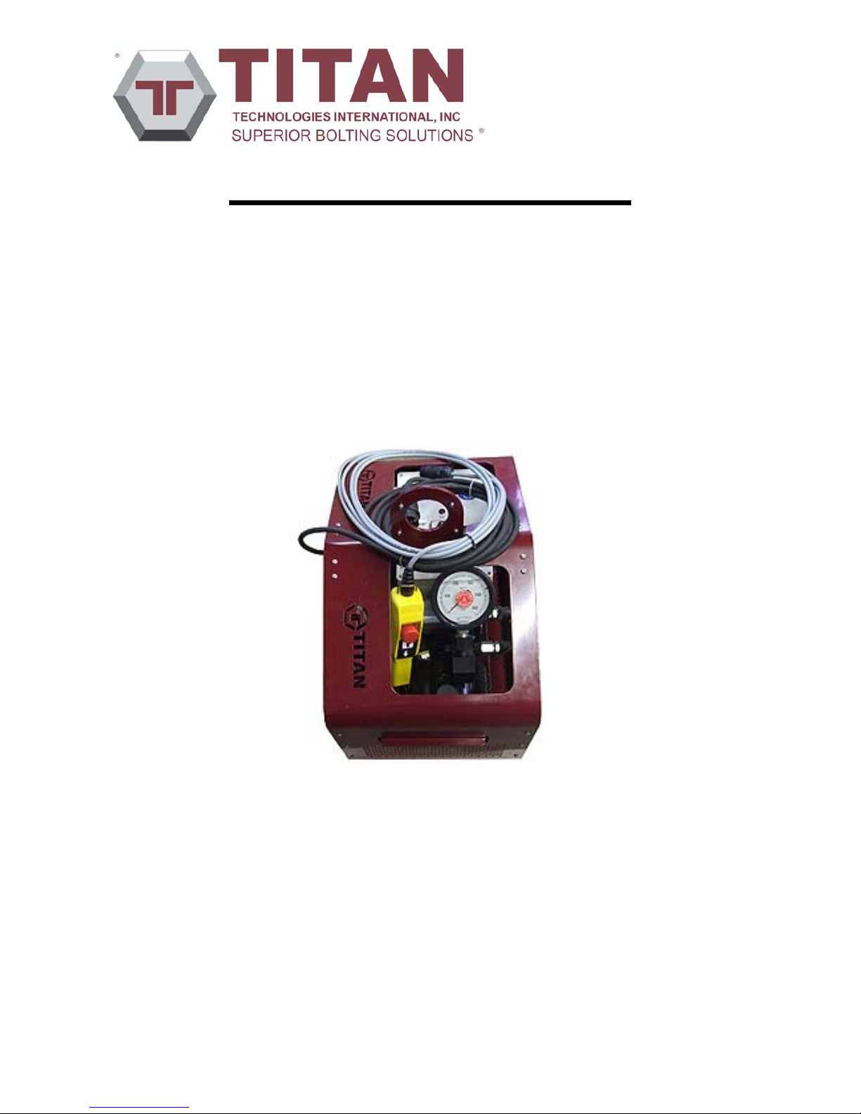
Note: The TITAN®WindMaster™ 2010 Pump produces extremely high
hydraulic pressure. Extreme care must be taken to ensure safety.
Failure to do so may result in severe injury or death.
Before starting the work, please make sure that the oil level in the pump tank is
correct. The oil gauges should be filled with oil. Filling the tank approximately 1
cm under the tank caps is allowed. In some cases it can be necessary to refill the
device with oil.
Use only hydraulic oil and never aggressive oil, because it can results in
damaging your seals.
NOTE: CHECK AND ENSURE THAT THE APPLICATION AND ITS
THREADED FASTERNERS ARE SUITABLE FOR THE MAXIMUM
OPERATING PRESSURE.
HINT: ALSO, ONLY HOSES AND CONNECTIONS WITH SUITABLE
OPERATING PRESSURE RATINGAND SAFETY FACTORS SHOULD BE
USED. CHECK ALL HOSES FOR KINKING AND IF FOUND, REPLACE
PRIOR TO PRESSURIZING. FOR BEST RESULTS AND OPTIMUM SAFETY,
USE ONLY TITAN®SUPPLIED HOSES, CONNECTIONS AND ACCESSORIES.
ATTENTION: NEVER USE THE HOSES AS A CARRING HANDLE.
The high-pressure hose must be shifted as straight-lined and directly as possible,
in each case never exceed the minimum bending radius. The hose should not be
overdriven or loaded. Sharp edged parts can damage the hose. Pay attention
particularly to the suitable threaded connections.
For tightening the threaded bolt or stud connection we recommend normal
spanners without extension, in order to avoid overloading at the threads. For the
hose connectors only use the threaded bolt or stud connections specified in our
catalogue under accessories.
Dirt particles in the hydraulic system can lead to damages at the cylinder faces
and at the valve seats, therefore replace dirty hydraulic fluid before starting.
After all components are examined for the structural integrity necessary for the
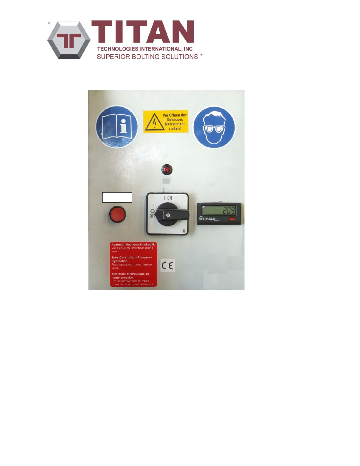
desired pressure, the device can be plugged in to the electricity supply. Turn the
main switch to the pos.1 to start the pump.

TITAN Technologies International, Inc.®
9001 Jameel Street, Suite 180 • Houston, TX 77040
http://www.titanti.com
By operating the tracer ⇑on the hand remote control (Fig. 2) the hydraulic
pressure develops. Before starting, in each case, check the adjusted pressure
(chap. Pressure adjustment).
Fig. 2
By operating the tracer ⇓on the remote control the pressure can be reduced
again.
If you are not using the pump motor, please switch it off (Main switch on Pos.0)
In order to avoid unnecessary wear and thermal loads on the device.
Do not touch the motor and parts near the motor after using it, since the
surfaces can be hot.
Pressure adjustment
The output / consumer pressure can be determined by adjusting the low pressure
at the pressure limiting valve. This adjusts the input pressure of the pressure
converter.
Turning clockwise (+) will increase the pressure, turning counterclockwise (-) will
reduce the pressure. The pressure converter operates with a conversion ratio of
1:13. This means, for example, that 10 bar of low pressure will generate an
output pressure of 130 bar.
The electric hydraulics pumps are factory-installed and adjusted to 1000 bar
initial pressure.
CAUTION: Disconnect all hoses and tensioners PRIOR to adjusting the
pressure.

TITAN Technologies International, Inc.®
9001 Jameel Street, Suite 180 • Houston, TX 77040
http://www.titanti.com
Venting
Because air is compressible, air within the system can lead to accidents. It is
therefore essential to vent the system of air, prior to using the pump, hose and
tensioner before starting the work. To accomplish this, let the pump run at a low
pressure until the hydraulic system is fully vented.
•Screw in the pressure limiting valve by approx. one revolution from the
point at which the spring takes effect, set switch I, to motor on, and vent
the entire system at the breather screw of the tensioner or at the end of
the hose until pure oil escapes without bubbles.
•Make the desired pressure adjustment (Chap. Pressure adjustment).
Coupling of the high-pressure hoses
CAUTION: IT IS VERY IMPORTANT THAT THE TWO HALVES OF THE
COUPLING ARE ALWAYS CLEANED THROUGHLY BEFORE CONNECTING.
Dirt in the halves of the coupling also makes the complete connection more
difficult, obstructing the flow of fluid because it will be possible that the two balls
will not open fully.
NOTE: THEREFORE, PLEASE ALWAYS CHECK THAT THE COUPLING IS
FULLY ENGAGED OR, IF SCREW UNIONS ARE EMPLOYED, THAT THEY
ARE FULLY SCREWED IN.
NOTE: WE RECOMMEND THAT THE DUST CAPS SHOULD ALWAYS BE
SCREWED ON WHEN THE COUPLING IS DISCONNECTED.
WE WILL NOT ACCEPT GUARANTEE CLAIMS RESULTING FROM THE
INCORRECT USE OF OUR EQUIPMENT OR FROM THE USE OF
EQUIPMENT OR SPARE PARTS MADE BY OTHER MANUFACTURERS.
NOTE: QUALIFIED PERSONNEL MUST CONDUCT ALL REPAIRS OR
MODIFICATIONS TO THE PUMPS. INCORRECT HANDLING CAN CAUSE
THE GUARANTEE TO BE VOIDED.

TITAN Technologies International, Inc.®
9001 Jameel Street, Suite 180 • Houston, TX 77040
http://www.titanti.com
Handling instruction for the heating mechanism
Heate
r
Fig. 3 Switch box, heater
•Switch-on the Power supply.
•By pressing the heating-button (see Fig. 3) the pump runs one minute in a
pressure-free circulation to warm up the oil.
- After first pressuring, the heating mechanism is out of action.
•If you want to use the heating-mechanism again (after pressuring), you
must switch off/on the pump.

TITAN Technologies International, Inc.®
9001 Jameel Street, Suite 180 • Houston, TX 77040
http://www.titanti.com
Safety hints
Apart from observing the general accident prevention regulations, the following
safety instructions must be observed to prevent life-endangering conditions,
damage and an increased accident hazard.
If leaks occur when pressure is applied, the pressure must be relieved
immediately. The leak must be sealed and defective components must be
replaced.
When repairs are made use original spare parts only. The unauthorised
replacement of damaged components with non-original spare parts is not
permitted.
All components must be handled exclusively as described in the
operating instructions and the general drawing. Changes to the
functional sequence or a different application are not allowed.
It must always check if the high-pressure hoses are connected correctly.
The high-pressure hoses must be laid such that they cannot be driven
over by vehicles or unnecessarily trodden by persons. Never lay hoses over
sharp objects (danger of cutting) and do not pinch or trap them.
Before the pressure is applied, the maximum working pressure (without
consumers) must be adjusted by an authorised person at the pressure-
limiting valve (Chap. Pressure adjustment).
The unit is not fitted with a safety valve. The maximum system pressure
of 2500 bar must never be exceeded.
Repairs must only be conducted when the system is depressurised and
disconnected from the power.
Verify the oil level before each commissioning.
You must carry protection eyeglasses while working with high-pressure
hydraulic aggregates.
In the case of use of a remote control, pay attention to electromagnetic
radiations.

TITAN Technologies International, Inc.®
9001 Jameel Street, Suite 180 • Houston, TX 77040
http://www.titanti.com
Short guidance
The following steps must be taken before the first start:
•Fill up hydraulic fluid (e.g. ISO VG 46) at the filler pipe if necessary until
the oil gauge is filled with oil
•Connect the plug to a power source (Consider the electrical data)
•Disconnect all hoses to the consumers
•Close the manual shut-off valve (otherwise pressure-free circulation)
•Adjust the working pressure at the pressure limiting valve
•Build up the pressure by operating the tracer ⇑
•Stop building up the pressure by releasing the tracer ⇑
•Release the pressure by opening the manual shut-off valve or by
operating the tracer ⇓
CAUTION: ALWAYS CHECK THE MAX. ADJUSTED HYDRAULIC
PRESSURE FIRST WITHOUT THE HOSES OR TOOLS CONNECTED.
THE MAX. PERMISSIBLE HYDRAULIC PRESSURE OF THE SUPPLIED
HYDRAULIC GAUGE MUST NOT BE EXCEEDED.
TURN THE REGULATING KNOB COUNTERCLOCKWISE →REDUCES THE
PRESSURE
TURN THE REGULATING KNOB CLOCKWISE →INCREASES THE
PRESSURE
Always observe the hydraulic pressure gauge when applying pressure to the
pump.
Safety requires that you read very carefully and understand fully the operation
instructions, prior to turning on and operating the pump.

TITAN Technologies International, Inc.®
9001 Jameel Street, Suite 180 • Houston, TX 77040
http://www.titanti.com
Maintenance
The first oil change and cleaning of the oil tank and the suction filter of the pump
should take place after approx. 50 service hours. All other oil changes depend on
the degree of contamination of the environment. The intervals must be
determined individually from case to case. It is usually sufficient to conduct this
maintenance work in an annual interval. However extreme conditions may
require much shorter intervals.
Cleaning the oil tank
It is only necessary to release the lid fastening screws on the unit and the entire
pump-motor unit can be removed. Then rinse out the oil tank with oil only. DO
NOT USE TEXTILES!!!
The suction filter of the pump must be examined and cleaned if necessary during
fluid changes.
High-pressure hoses
The high-pressure hoses must be examined to detect ageing (cracks, pores) and
must be replaced after 5 years at the latest.
Repair instructions
If repairs become necessary use original spare only. Use of non-Titan parts may
cause severe safety risk at worst and inferior performance at best.
Ensure extreme cleanliness during maintenance work on the pump to preserve
its function and service life.
The pressure converter must not be dismounted. All necessary repairs can only
be conducted by TITAN®or a authorized and certified TITAN®service technician.

TITAN Technologies International, Inc.®
9001 Jameel Street, Suite 180 • Houston, TX 77040
http://www.titanti.com
Trouble Shooting Chart
Most faults have a simple cause and can therefore be rectified on site, i.e. time
losses and transport costs can be avoided. Some of the most frequent faults are
explained below. If this information is insufficient, please consult our technical
support or your authorized TITAN®Repair Facility.
Pump does not pressurize
•Air in pump Switch motor on and off several times
•Changeover valve jammed Switch by hand
•Pressure converter defective Replacement necessary
Pump pressurizes inadequately
•Air in pump Switch motor on and off several times
•Gear wheels worn out Replacement necessary
Pump does not reach pressure
•Pump worn Replacement necessary
•Valve worn Leak to tank
•Relief valve misadjusted Adjust pressure limiting valve
Pressure cannot be relieved
•Solenoid valve jammed Switch by hand
Technical data
1. Gear pump
Operating pressure p max: 230 bar
Conveyed volumes: LP – 1.5 l/min until 4 l/min up to 230 bar
2. Pressure Intensifier
3.
Converting ratio 1:13
Operating pressure p max: 2500 bar
Conveyed volumes: HP – 0.9 l/min up to 2500 bar

TITAN Technologies International, Inc.®
9001 Jameel Street, Suite 180 • Houston, TX 77040
http://www.titanti.com
4. Motor
Electric motor Power and the AC network on the motor type plate
Function: Switch 1 at position “I” – Motor runs
Switch 1 at position “0” – Motor stops
5. 4/3 way Solenoid valve Y1/Y2
Voltage supply: 24V
Function: Position Y1 – Pressure increases
Position Y2 – Pressure decreases
Central position – Pressure-free circulation
6. Hydraulic delockable check valve HRV1
Function: Opens with the manipulation of the direction
control valve Y2
7. Pressure limiting valve DBV1
Function: Regulates the low pressure continuously
from 0 – 230 bar (theoretically 192 bar)
Correspondingly the high pressure
from 0 – 2500 bar
8. Electrical control
Transformer
Control circuit board with fuses
Remote control
9. Remote control
Function: Tracer I (⇑) execute the directional control
valve Y1
Tracer II (⇓) execute the directional control
valve Y2

TITAN Technologies International, Inc.®
9001 Jameel Street, Suite 180 • Houston, TX 77040
http://www.titanti.com
10.Heater
Function: The pump runs one minute in a pressure-free
circulation to warm up the Oil
11.General
Weight incl. oil: Approx. 35 kg (type dependent)
Dimensions [mm]: HxWxL – 525x360x585
Tank capacity: Approx. 3 l carryable
Motor connection: Plug with 5m cable length
Pressure fluid: Hydraulic oil 1.3 to 3.5 E at 30° C
Temperature range: -30° to +80° C
Remote control: Pressure Increase/decrease switch and 5 m
cable length

TITAN Technologies International, Inc.®
9001 Jameel Street, Suite 180 • Houston, TX 77040
http://www.titanti.com
Hydraulic-schematic

TITAN Technologies International, Inc.®
9001 Jameel Street, Suite 180 • Houston, TX 77040
http://www.titanti.com
Electric-schematic

TITAN Technologies International, Inc.®
9001 Jameel Street, Suite 180 • Houston, TX 77040
http://www.titanti.com
Appendix
Before starting the plug has to be
replaced by the venting screw!
For each transport replace the
plug again!
Table of contents
Other Titan Power Pump manuals
Popular Power Pump manuals by other brands

MULTIQUIP
MULTIQUIP QP3TH Operation and parts manual

WELCH-ILMVAC
WELCH-ILMVAC DUOSEAL 1405B-01 owner's manual

BLACKMER
BLACKMER XRLW1.25A Installation, operation and maintenance instructions

Simplex
Simplex G3 instructions

Dover
Dover PCG Blackmer XRLF1.25B Installation, operation and maintenance instructions

Pentair
Pentair MYERS ME40MC-11-CI owner's manual