Eaton 596 User manual

Installation, Operation & Maintenance Manual
Control Panels for Automatic Self-Cleaning Strainers
Model 596 and Model 2596
IOM Controls 04/2020
REV
B.
Page 1
of 9
Eaton Filtration LLC, 44 Apple Street, Tinton Falls, NJ 07724 www.eaton.com/filtration Phone:
732-212-4700
Read all the following information and instructions prior to installing and operating the e
quip
me
nt.
Failure to comply with these instructions could result in bodily injury or property
da
m
a
ge.
TABLE OF CO
N
T
EN
T
S
Introduction ...................................................................... 1
Receiving, Handling, and Inspection ................................. 2
Storage .............................................................................. 2
Operating Modes .............................................................. 2
Continuous Backwash .......................................... 2
Automatic Backwash (Timed Cycle) .................... 2
Valves ................................................................................ 2
Valve Selection..................................................... 2
Backwash/Blow-Down/Drain Valve ..................... 3
Electric Actuators ................................................. 3
Pneumatic Actuators............................................ 3
Differential Pressure Switches .......................................... 4
Switch Description................................................ 4
Mounting, Piping and Wiring ............................... 4
Adjustment........................................................... 4
Control Panel..................................................................... 5
Description ........................................................... 5
Cycle Time Sequence............................................ 5
Standard Features................................................ 5
Operating Modes………………………………………………………….. 6
Changing Backwash Timer Settings………………………………. 6
SmartWire-DT Error Messages……………………………………… 7
System Error Messages………………………………………………... 7
Electrical Schematic Diagram........................................... 8
Typical Installation ........................................................... 9
IN
T
R
OD
U
CT
I
O
N
An automatic, self-cleaning strainer requires a control
system to provide flexibility and optimize performance of
the straining operation. A number of standard options
are available or specify a custom designed control
system.
This manual will define the installation requirement,
operation, and maintenance of the Eaton control system.

Installation, Operation & Maintenance Manual
Control Panels for Automatic Self-Cleaning Strainers
Model 596 and Model 2596
IOM Controls 04/2020
REV
B.
Page 2
of 9
Eaton Filtration LLC, 44 Apple Street, Tinton Falls, NJ 07724 www.eaton.com/filtration Phone:
732-212-4700
RECEIVING, HANDLING AND
INS
P
E
CT
I
O
N
The control panel, motor and accessories have been packed
in a separate container but shipped with the strainer. This
provides protection from damage during
transit and also provides for ease of storage if the controls are
not installed immediately. When first received the following
must be done:
1. Unpack and inspect for damage.
2. Report any damage to carrier immediately.
3. If controls are not installed at this time, refer to Storage
Instructions.
STORAGE
INS
T
RU
CT
I
O
NS
Repack all components in the original carton and reuse all
protective packaging. Store all components in an indoor,
clean, and dry environment. Protect from temperature
extremes. Mark cartons to protect from handling abuse.
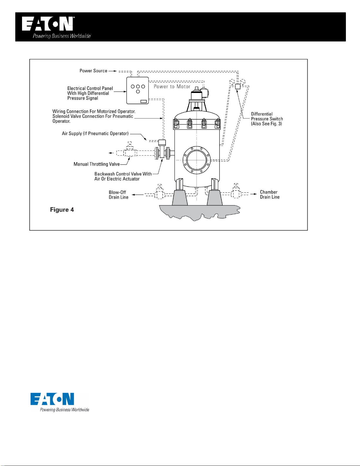
STRAINER MODE OF OP
ERA
T
I
O
N
CONTINUOUS
BA
C
K
W
ASH
This is the most effective way to keep the strainer element
“clean”and have the least pressure loss. Continuous element
washing can be accomplished with a minimum of control
devices. However, it offers no flexibility of operation when
there are significant changes in flow volume or solids content
of the fluid.
The “drain”line requires a blow-down/drain valve which may
be manually operated. Normal valve position is CLOSED.
The backwash line requires a backwash valve which may be
manually operated on the backwash line. Normal valve
position is FULL OPEN.
The backwash motor requires a motor starter. Furnish with
overload protection and fused disconnect.
STRAINER MODE OF OP
ERA
T
I
O
N
AUTOMATIC BACKWASH (TIMED C
Y
C
LE)
The preferred mode of operation for a self-cleaning strainer is
one where the control system will permit both intermittent and
continuous backwash as required by operating conditions.
The “drain”line requires a blow-down/drain valve which may
be manually operated. Normal valve position is CLOSED.
The backwash line requires a backwash valve, either electrically
or pneumatically operated on the backwash line. This valve
should operate only in the FULL OPEN or FULL CLOSED position.
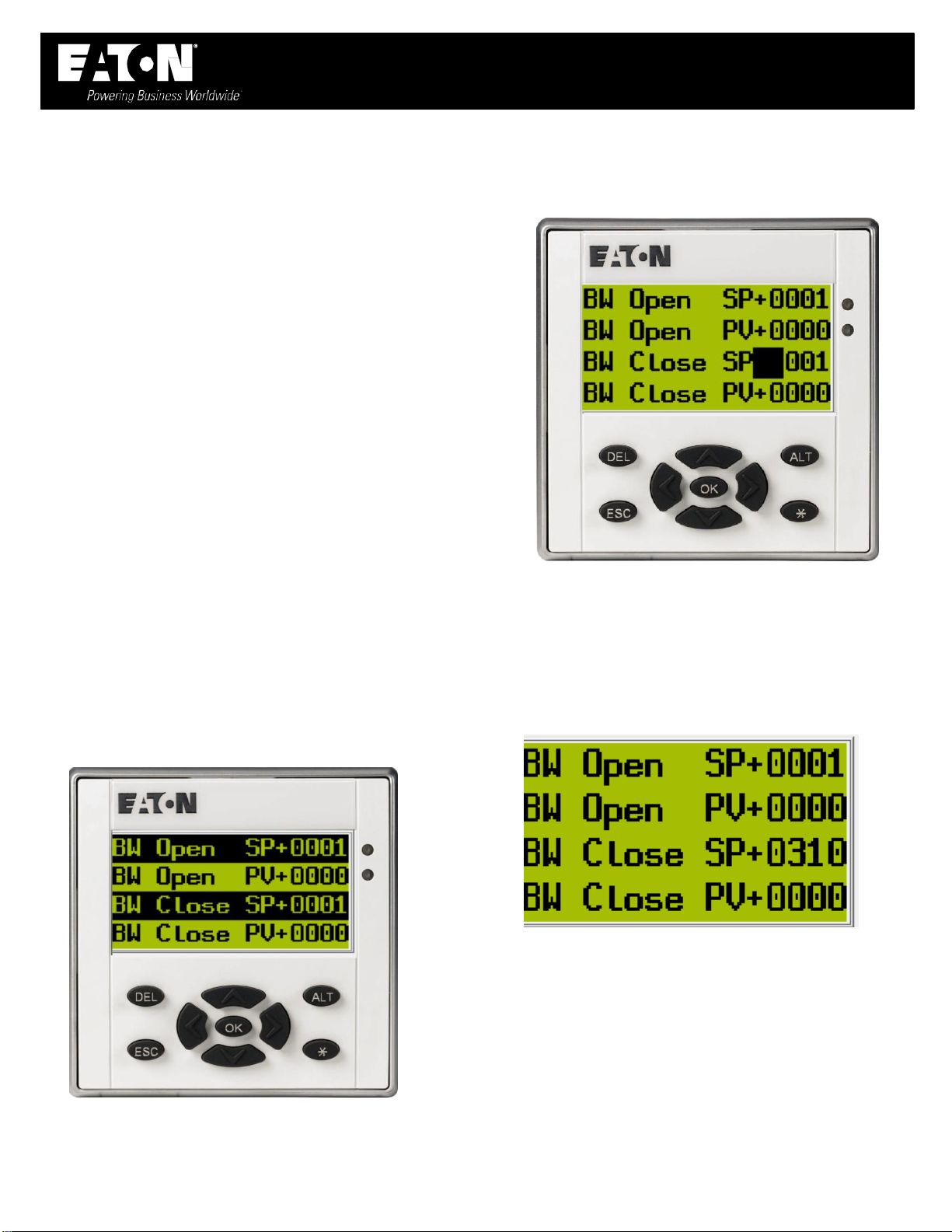
A fully adjustable differential pressure switch is furnished to
detect the increase of pressure across the strainer. It will
activate a backwash cycle independent of the time-controlled
sequence. NOTE: Set switch at 2psi over the observed clean
pressure drop.
Eaton provides a control panel, containing all necessary relays,
timers, lights, switches, etc. This will initiate and monitor the
intermittent backwash cycles.
VALVE
SELE
CT
I
O
N
Several important factors to consider when selecting the
necessary valves.
Valve Type: Gate, plug, and butterfly valves can be used.
However, ball valves provide the most advantages. Ball valves,
when “Full Open”provide a uniform and straight flow path
minimizing pressure loss. Since only 90° rotation of the stem is
required to go from “Fully Closed”to “Fully Open”motorized
operators are easily adapted and provide short cycle times.
Valve Material: Iron, bronze, steel, and stainless steel are the
most common. Select valve and trim material that will not
corrode or react with the process fluid or the environment.
Pressure Rating: Select the valve class with a pressure rating
equal to or greater than the system design pressure.
Connection: Select a valve with end connections (flanged,
threaded, etc.) that will provide ease of maintenance and
trouble-free service.

Installation, Operation & Maintenance Manual
Control Panels for Automatic Self-Cleaning Strainers
Model 596 and Model 2596
IOM Controls 04/2020
REV
B.
Page 3
of 9
Eaton Filtration LLC, 44 Apple Street, Tinton Falls, NJ 07724 www.eaton.com/filtration Phone:
732-212-4700
Size
Backwash
Chamber Drain
10” to 16”
1”
¾”
18” to 30”
3”
2”
36
6”
3”
STRAINER MODE OF OP
ERATI
O
N
CONTINUOUS
BA
CKW
ASH
Several valves are required for various applications. Ball valves
of the proper size, end connection, material, and pressure
rating are recommended for these services.
Manually operated valves are best suited for “blow-down”
and “chamber drain”service. They may also be used for
continuous backwash service.
For timed cycle backwash, the valve should be operated by an
electric or pneumatic valve actuator.
Larger size strainers require both a “blow-down drain”and a
“chamber drain”for the body.
The table below lists the service functions and sizes of valves
for standard strainers.
Model 596
Size
Backwash
Chamber Drain
2”, 3”, 4”
1”
¾”
6”, 8”
1
½”
¾”
Model 2596
PNEUMATIC
A
CT
UA
TO
RS
A double-acting piston design that uses a clean air supply
of 40-125 psi pressure, powers the actuator properly.
Using an electric signal, a solenoid pilot valve controls the
air supply to the actuator.
Most actuators have pipe thread connections (NPT)
located so that the solenoid valves may be mounted with
minimal tubing runs.
Customer must run wiring and conduit from the control
panel terminals to the solenoid valve (see Fig 2).
Piping (or tubing) is required from the solenoid valve to
the air supply system (this is customer scope of supply).
The solenoid pilot valve must be piped to the actuator so
that the backwash valve will close when there is no
electric power to the solenoid.
SAMPLE OPERATION USING 3-
WAY SOLENOID V
AL
V
E
Power On: Air supply from the pilot valve to actuator is “Open”
but vent is “Closed.”
Power Off: Air supply to actuator is “Closed.” Vent connection
is “Open.”
ELECTRIC
A
CT
UA
TO
RS
The required actuator size depends on the backwash
valve torque requirements. The motors are “shaded pole”
or “split capacitor” type.
115 Vac, 10 Hz actuator motors are standard, other
voltages are available.
The standard actuators require simple wiring from the
control panel to the actuator (see Fig 2).

IOM Controls 04/2020
REV
B.
Page 4
of 9
Eaton Filtration LLC, 44 Apple Street, Tinton Falls, NJ 07724 www.eaton.com/filtration Phone:
732-212-4700
Installation, Operation & Maintenance Manual
Control Panels for Automatic Self-Cleaning Strainers
Model 596 and Model 2596
DIFFERENTIAL PRESSURE SWITCHES
SWITCH DESCRIPTION
(SINGLE OR DUAL ELEMENT)
A diaphragm type differential control with single switch is
standard. It initiates a backwash cycle whenever a high
differential pressure drop occurs across the strainer. A dual
element switch is optional where operation requires the first
switch to initiate the backwash cycle. The second switch
activates on further increasing differential pressure and
energizes a visual or audible alarm, calling for operator
assistance.
DIFFERENTIAL PRESSURE
SWI
T
CHES
The differential pressure switch easily mounts on the
control panel supports or attached to a bracket that is
welded to the strainer body.
CAUTION: Never drill into the strainer body
to mount instrumentation or support
brackets.
CAUTION: Welding brackets to cast iron units
is not recommended and should be avoided.
The switch is piped to the pressure connections furnished on
the inlet/discharge nozzles of the strainer as shown in Fig 1.
Customer must supply and run wiring and conduit between the
differential pressure switch and the control panel. See Fig 2 for
wiring connections.
DIFFERENTIAL SWITCH
A
DJU
STMENT
While it is possible to use other equipment than what is
described below, any installation should have the items
described here.
Equipment to be furnished by customer:
2 calibrated pressure gauges
2 gauge valves with drain
2 tees, tubing, and fittings
All items suitable for 1/4” NPT connections
Install all equipment as shown in Fig 1. Open the gauge valves
and record the pressure readings at inlet/discharge of strainer
operating at rated flow. The difference in reading is the
“Normal” pressure drop across the system. Close both gauge
valves. Set switch at “Normal Plus 2 psi” using the adjustment
screw at the calibrated scale. To simulate a high differential
pressure, carefully vent the “outlet” side gauge valve only.
Note the pressure difference at which the switch is “activated.”
Using the adjustment screw on top of the switch, adjust until
switch activates at the proper set point. The “High”
alarm
setting
(optional) should be set at “Normal Plus 4 psi.” Special
applications may require other settings than those given above.
Switch should be re-calibrated at least every 6 months.

IOM Controls 04/2020
REV
B.
Page 5
of 9
Eaton Filtration LLC, 44 Apple Street, Tinton Falls, NJ 07724 www.eaton.com/filtration Phone:
732-212-4700
Installation, Operation & Maintenance Manual
Control Panels for Automatic Self-Cleaning Strainers
Model 596 and Model 2596
CONTROL PANEL DESCR
I
PT
I
O
N
The ACS Series Control Panel is a rugged electro-mechanical
unit made with industrial grade components and suitable of
outdoor (NEMA 4) installation. The enclosure houses all
components, is compact in size and is offered in two
configurations:
ACS-2S: All standard features and includes motor and starter
for backwash arm for 120 volt-single phase power supply
ASC-3S: All standard features plus motor starter for backwash
motor and transformer for 460 volt-3 phase power supply
The ACS line of control panels allows operation either in the
Manual or Auto modes. In the Manual mode, the strainer will
continuously backwash. In the Auto mode, the strainer is
allowed to backwash according to the preset timing cycle or
when the differential pressure switch is activated.
NOTE: The customer determines the timing cycle
length and changes it as required.
The control logic protects the strainer from sudden high
quantities of solids or an improperly adjusted timer cycle.
Whenever the differential pressure switch is activated, it
overrides the timer circuit and opens the backwash valve.
NOTE: An On-Off cycling of the backwash
valve will occur.
If frequent activation of the differential pressure switch is
evident, the timer cycle must be re-set to backwash more
often.
The panel door locates the selector switch and the indicating
lights. The weatherproof rating is maintained as long as the
lamp lenses are not broken and are not removed.

IOM Controls 04/2020
REV
B.
Page 6
of 9
Eaton Filtration LLC, 44 Apple Street, Tinton Falls, NJ 07724 www.eaton.com/filtration Phone:
732-212-4700
Installation, Operation & Maintenance Manual
Control Panels for Automatic Self-Cleaning Strainers
Model 596 and Model 2596
OPERATING MODES
DESCRIPTIONS
OFF MODE
Power light illuminated; 120 VAC power applied across
the “common” and “close” valve terminal connection.
No other circuits energized.
ON MODE
Backwash valve open, strainer motor running,
"BACKWASH ON" indicator illuminated, (monitor
differential pressure switch, if differential pressure
closes then “HIGH DIFFERENTIAL” indicator
illuminated, HI-DP alarm contact closes).
AUTO MODE
Timer range limits for BACKWASH ON (valve open) is 1
to 1440 minutes.
Timer range limits for BACKWASH OFF (valve closed) is
1 to 1440 minutes.
CHANGING THE BACKWASH
TIMER SETTINGS
To change timer settings press ALT button.
Use the UP or DOWN arrow buttons to move the cursor to
select lines “BW Open SP+”or “BW Close SP+”.
Press OK button to edit the BW set point.
Use UP and DOWN arrow buttons to increase or
decrease value in selected number column.
Use LEFT and RIGHT arrow buttons to select the number
column.
When the value is completed (shown set for 310
minutes/seconds above), press the OK button to move
the cursor to BW timer set point select mode. Then
press ESC key to leave BW timer edit mode.

IOM Controls 04/2020
REV
B.
Page 7
of 9
Eaton Filtration LLC, 44 Apple Street, Tinton Falls, NJ 07724 www.eaton.com/filtration Phone:
732-212-4700
Installation, Operation & Maintenance Manual
Control Panels for Automatic Self-Cleaning Strainers
Model 596 and Model 2596
SMARTWIRE-DT ERROR
MESSAGES
The SmartWire-DT system has and the ability to detect
most hardware errors. If a hardware error occurs the
screen will display what device and node is damaged or
disconnected. If more than one node is damaged or
disconnected the screen will cycle though all errors
present.
SYSTEM ERROR MESSAGES
Motor Overload
If there is a motor overload, the following message will
flash on the screen.
Hi DP Backwash
Hi DP backwash is indicated by the red LED and
with a change of state on Hi DP backwash relay
output
Motor Protector disconnect shown in the Open or Tripped
position.
Motor Protector Disconnect Switch shown in the Closed position.

IOM Controls 04/2020
REV B.
Page 9of 9
Eaton Filtration LLC, 44 Apple Street, Tinton Falls, NJ 07724 www.eaton.com/filtration Phone: 732
-212-4700
Installation, Operation & Maintenance Manual
Control Panels for Automatic Self-Cleaning Strainers
Model 596 and Model 2596
TYPICAL
INSTALLA
T
I
O
N
North America
44 Apple Street
Tinton Falls, NJ 07724
Toll Free: 800 656-3344
(North America only)
Tel: +1 732 212-4700
Europe/Africa/Middle East
Auf der Heide 2
53947 Nettersheim, Germany
Tel: +49 2486 809-0
Friedensstraße 41
68804 Altlußheim, Germany
Tel: +49 6205 2094-0
An den Nahewiesen 24
55450 Langenlonsheim, Germany
Tel: +49 6704 204-0
China
No. 3, Lane 280,
Linhong Road
Changning District, 200335
Shanghai, P.R. China
Tel: +86 21 5200-0099
Singapore
100G Pasir Panjang Road #07-08
Singapore 118523
Tel: +65 6825-1668
Brazil
Av. Ermano Marchetti, 1435 -
Água Branca, São Paulo - SP,
05038-001, Brazil
Tel: +55 11 3616-8461
For more information, please
email us at filtration@eaton.com
or visit www.eaton.com/filtration
© 2020 Eaton. All rights reserved. All trademarks and
registered trademarks are the property of their respective
owners. All information and recommendations appearingin
this brochure concerning the use of products described
herein are based on tests believed to be reliable. However,
it is the user’s responsibility to determine the suitability for
his own use of such products. Sincethe actual use by
othersis beyond our control, no guarantee, expressed or
implied, is made by Eaton as to the effects of such use or
the results to be obtained. Eaton assumes no liability
arising out of the use by othersof such products. Nor is the
information herein to be construed as absolutely complete,
since additional informationmay be necessary or desirable
when particular or exceptional conditions or circumstances
exist or becauseof applicable laws or government
regulations.
US
04-2020
This manual suits for next models
1
Table of contents