Eaton INTERNORMEN DNR Series Guide

This manual is effective for all filters of the type series DNR 405-635, DNR 630, DNR 1001-8201, DNR 1005-8205, DNA 250-2050,
DNL 630, EDNR, EDNA and EDNL and related specifications. It contains certain requirements and instructions which ensure
unobjectionable operation of the filter. It can be completed with specific additional instructions by the operator himself if necessary.
The pressure filters listed above are intended for the filtering of liquid media.
1. Safety instructions
- Prior to operating the filter, manual and maintenance instructions have to be read carefully.
- Follow the instructions of this manual under any circumstances!
- The manufacturer does not assume liability for any damage, which occurs due to disregarding these instructions.
- If operations are carried out differently, the safety of the pressurized device can not be assured!
- Operating conditions given in the data sheet, especially excess pressure, temperature range and operating fluid, have to be
followed unconditionally. Variation of these parameters can cause damage to important pressure holding parts and sealing. Also
take in consideration the compatibility of filter components with the operating fluid.
- Under working conditions the filter housing is pressurized. Do not try to loosen or remove any part of the filter or the filter housing
during operation. The operating fluid could escape at high pressure and high temperatures.
This does not apply for parts of the decompressed or the turned off side of the filter (see „Maintenance“).
- Leaking operating fluid always bears the danger of injuries and burns!
- Do not open the filter housing until you made sure it is not pressurized any more!
- Touching parts of the filter may cause burning, depending on the operating temperature.
- When exchanging the filter keep in mind that it might have operating temperature. Danger of burning!
- Always wear safety goggles and gloves when working on the filter!
- If you come into contact with the operating fluid please follow the instructions of the fluid manufacturer!!
- Only use original spare parts.
2. Installation
The filter is supplied and delivered ready to be installed. The fitting position of the filter is vertical. The filter has to be fitted with
fastening screws in size and amount according to the corresponding fastening bore holes of the filter housings. The fitting of the filter
has to be carried out in the way that the least possible transmission of tensible forces on the filter housing and the change-over valve
is given. The connection of the pipework has to be made with flanges for pipework.
Ensure upon assembling that
- no dirt and no impurities of foreign fluids penetrate the filter
- the connections for input and output are correctly connected to the pipe system
- the pipe system is connected with the filter; as stress-free as possible
- the extension to demount and the accessibility to the service elements is guaranteed
Filter with electrical respectively electronical clogging indicators have to be installed according to the unit specific conditions and
according to the technical parameters of the corresponding data sheets.
3. Commissioning
Before commissioning the completeness of the filter (filter elements and seals) and the cleanness have to be controlled.
Air bleeding of the controlled filter has to be carried out to the following instructions:
- The positioning pin of the selector shaft has to be located in the middle position
- Opening of the air-bleed screws or air-bleed connections (air-bleed connections according to data sheet 1651 and
connection of suitable airbleeding tubes with collecting pan for the flow out of the operating fluid
- Connection of the unit volume flow (reduced volume flow; from 10 to 50 l/min) until bubble-free operating fluid flows out of both
airbleeding tubes
- Disconnection of the unit volume flow
- Remove the airbleeding tubes and close the air-bleed bore holes or air-bleed connections (air-bleed connections
according to data sheet 1651)
- Connection to the required filter side at the positioning pin of the selector shaft
Take a look at the indicating labels and change-over indications at the filter.
4. Change of Elements
The changing of the filter elements is necessary when reaching the unit specific pressure difference respectively reaching the
maximum pressure difference given by the clogging indicator. If there is no unit specific definition, the change of the elements
should be done at a maximum of p 6 bar.
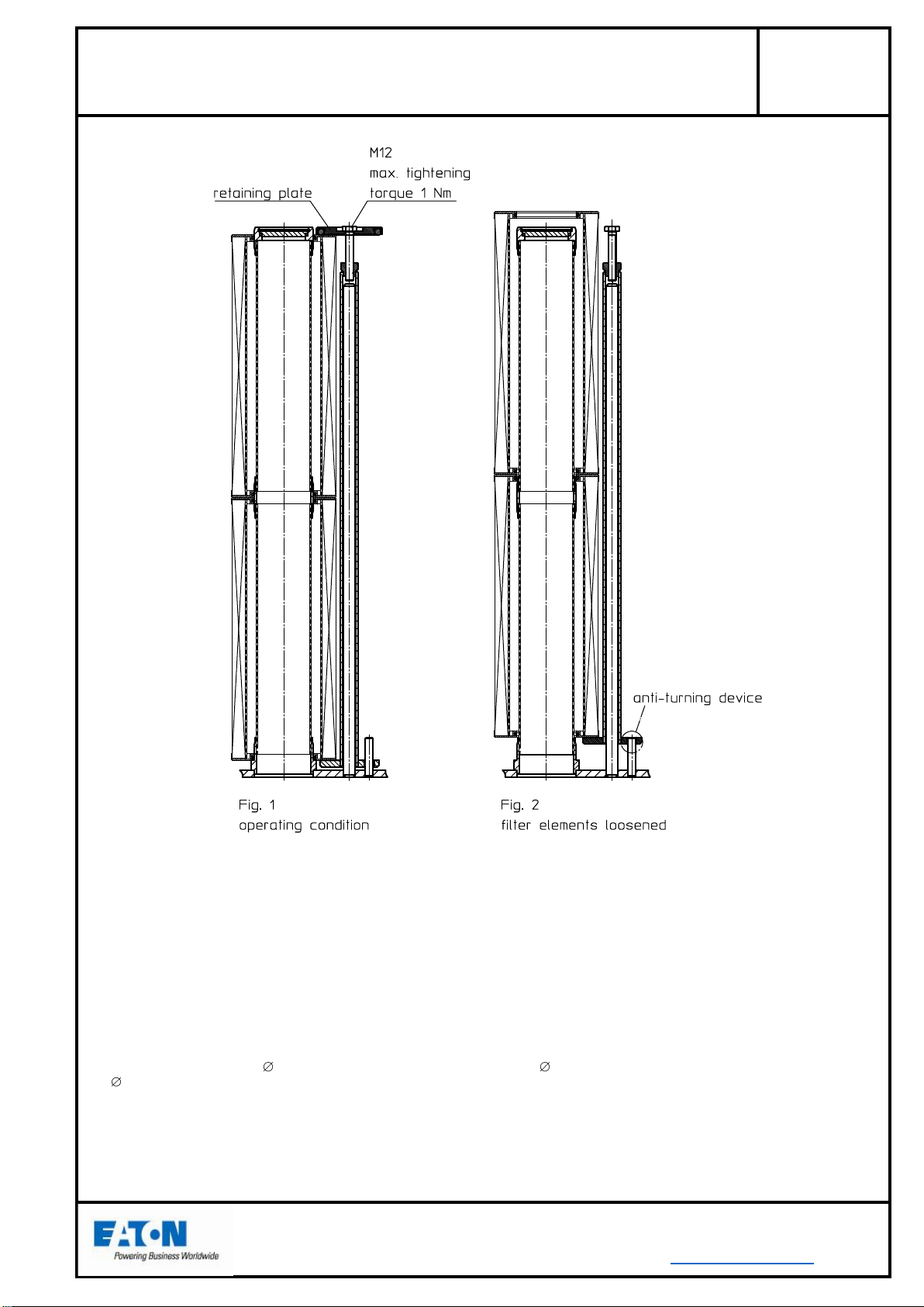
The filter element can be changed during operation. This has to be carried out as follows:
- Opening of the pressure balance valve
- Switching over the positioning pin from the operating side through the other side
(Take a look at the indicating labels and change-over indications at the filter)
- Closing the pressure balance valve
- Connect the air-bleed and the drain plug of filter side to be maintained with suitable pipes and place a collecting pan for the
operating fluid flowing out
Manual and maintenance instructions
for INTERNORMEN-Pressure filter, change-over
DNR, DNA, DNL, EDNR, EDNA, EDNL, relatd specifications
Sheet No.
21682-4D
Page 1/3
EDV 08/12 - Englisch
+49 (0)6205 2094-0
+49 (0)6205 2094-40
phone
fax
Friedensstrasse 41, 68804 Altlussheim, Germany
e-mail
url

- Opening of the air-bleed and drain plugs of the filter side to be maintained until no more operating fluid flows out
- Release of the screws of the lid of the filter side to be maintained and remove the filter lid
- Remove the filter elements
The handling of the lifting-out device place after guidance on page 3.
- Cleaning of the filter housing. Pay attention, that no dirt and no cleaning fluid get to the clean side (that means through the open
centering pivot into the filter elements)
- Fix the filter lid onto the filter housing and tighten the screw plugs. The screw have to be tightened over cross and have to be
tightened again after the first pressure load
- Closing of the drain plugs
- Opening of the pressure balance valve until bubble-free operating fluid flows out of the air-bleed connection
- Close the pressure balance valve and the air-bleeder
Now, the serviced filter side is ready for operation.
In general take care about the absolute cleanness during the changing of elements. No dirt respectively no impurities should
penetrate the filter. The new elements should be taken out of their packing shortly before they are replaced in the filter housing
because of mechanical damage.
During the changing of elements control the seals and their quality. Damaged seals have to be replaced by new ones.
Concerning the bolted connection at the filter lids the following turning moments are prescribed.
M16
M20
M24
M27
M30
M33
80 +/-8 Nm
160 +/-15 Nm
250 +/-25 Nm
400 +/-40 Nm
600 +/-60 Nm
700 +/-70 Nm
5. Cleaning of the Filter Element
Filter elements with filter materials such as glass fibre (VG) or paper (P) are not cleanable. They have to be replaced after the dirt
retention capacity has been reached. Filter elements with filter materials such a wire mesh (G) are cleanable and could be used
again.
The cleaning of the filter elements has to be carried out according to the cleaning specification for INTERNORMEN-Filter
elements (metal), shett-no. 21070-4 and 39448-4.
6. Pressure Difference Measuring
In case of filters installed with clogging indicators a permanent measuring of the pressure difference takes place. The indication
corresponds to the kind of clogging indicators; either visual or visual and electrical respectively electronical.
Additionally can of the filters DNR 1001-8201, DNR 1005-8205, EDNR 1001-8201 and EDNR 1005-8205 the measuring
connections G ¼“ could be installed on the selector shaft to be used for external pressure gauges.
Recommended are the measuring connections according to data sheet 1650.
7. Special application
Differing from the ordinary operation of the filter the filter can be used for system-dependent special operating modes.
- Operation in explosive areas
There are additional requirements for filters that are installed in explosive areas according to the
INTERNORMEN documentation No. 41269
“Addition to the operating and maintenance instructions for the application of filters in explosive areas”.
- Flushing operation for machines with an increased rate of delivery
There is an additional INTERNORMEN Documentation No. 51354 which is valid for the flushing operation with an increased
rate of delivery
“Addition to the operating and maintenance instructions for the flushing operation in machines”.
8. Service
The service will be performed by
EATON Technologies GmbH
Friedensstr. 41
D-68804 Altlussheim
Germany
phone: +49(0)6205-2094-0
fax: +49(0)6205-2094-40
Special questions about the operation of the filter will also be answered within this area.
Spare parts respectively wearing parts have to be ordered according to the spare part list of the filter-data-sheet.
Manual and maintenance instructions
for INTERNORMEN-Pressure filter, change-over
DNR, DNA, DNL, EDNR, EDNA, EDNL, relatd specifications
Sheet No.
21682-4D
Page 2/3
EDV 08/12- Englisch
+49 (0)6205 2094-0
+49 (0)6205 2094-40
phone
fax
Friedensstrasse 41, 68804 Altlussheim, Germany
e-mail
url

Manual and maintenance instructions
lifting-out device for INTERNORMEN-Pressure filter, change-over
DNR, DNA, DNL, EDNR, EDNA, EDNL, relatd specifications
The lifting-out device serves to release the filter elements from the mounting spigot.
Manipulating the lifting-out device:
- Remove the M12 screw and the retaining plate.
- Screw the M12 screw into the retainer until the upper filter element projects over the mounting spigot.
- The filter elements can now be removed by hand. The lower filter elements can also be removed by hand together with the lifting-out
device.
- Before inserting new filter elements, put the lifting-out device back into position. Ensure the correct position of the lower plate against
the anti-turning device (pin 12 mm in the intermediate filter base). The pin 12 mm must be introduced into the eccentric drill hole
15 mm of the lower plate.
- Insert the retaining plate and screw in the M12 screw, max. tightening torque 1Nm/hand-screwed.
EDV 08/12 - Englisch
Sheet No.
21682-4D
Page 3/3
+49 (0)6205 2094-0
+49 (0)6205 2094-40
phone
fax
Friedensstrasse 41, 68804 Altlussheim, Germany
e-mail
url
This manual suits for next models
11
Table of contents
Other Eaton Water Filtration System manuals

Eaton
Eaton DCF-3000 Owner's manual

Eaton
Eaton Cutler-Hammer 66A8060 User manual

Eaton
Eaton MAXILINE MBF Series User manual

Eaton
Eaton DA/EDA 106 User manual

Eaton
Eaton HCU2 User manual

Eaton
Eaton PSFi Series User manual

Eaton
Eaton 53BTX Owner's manual

Eaton
Eaton 30R User manual

Eaton
Eaton DWF 1505 User manual

Eaton
Eaton EDSF 1201-15001 Guide
Popular Water Filtration System manuals by other brands

BWT
BWT AQA drink TC200 Installation and operating instructions

deconta
deconta C 25 L operating instructions

BWT
BWT PERMAQ PRO 1810 Installation and operating instruction

Pure Pressure
Pure Pressure Axis Service manual

Antunes
Antunes AQ-RO-400-NT owner's manual

BWT
BWT PERMAQ COMPACT 51 Installation and operating manual