manuals.online logo
Brands
  1. Home
  2. •
  3. Brands
  4. •
  5. Eaton
  6. •
  7. Water Filtration System
  8. •
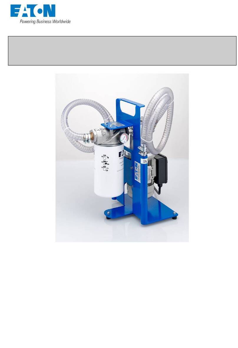
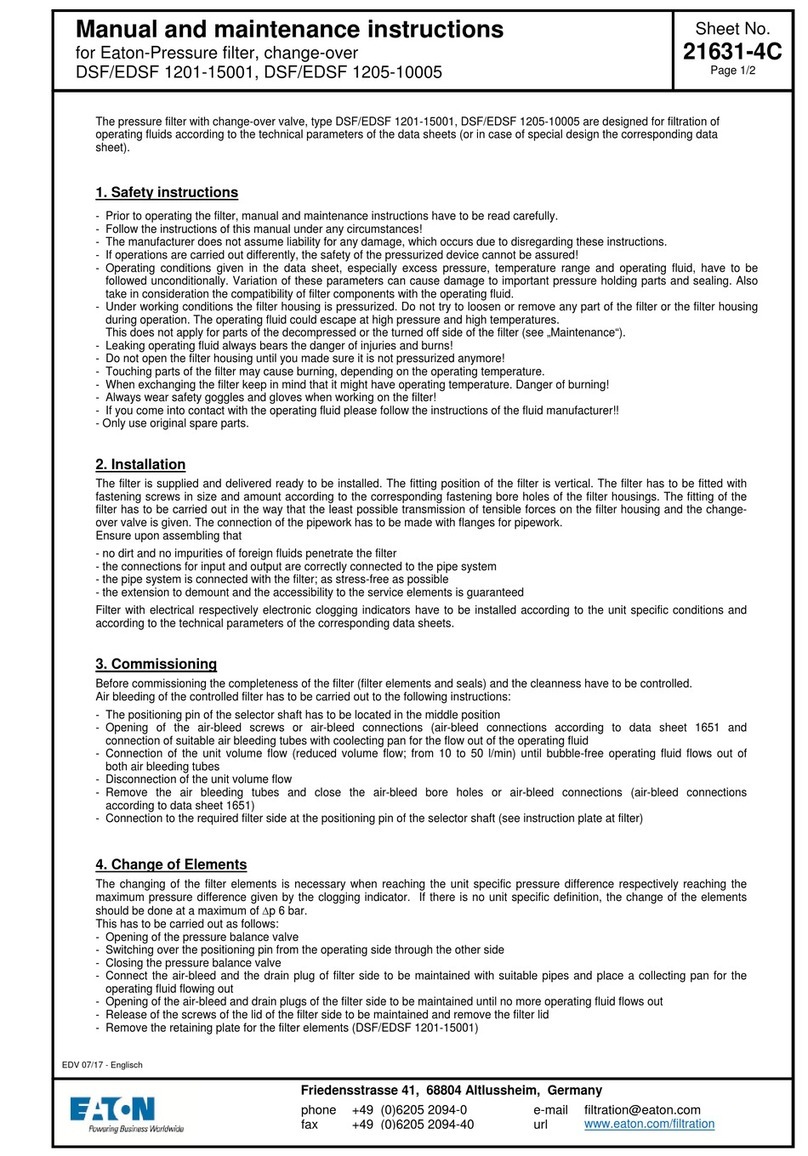
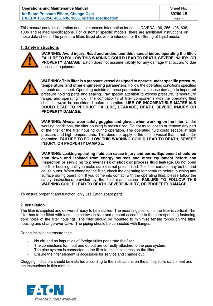
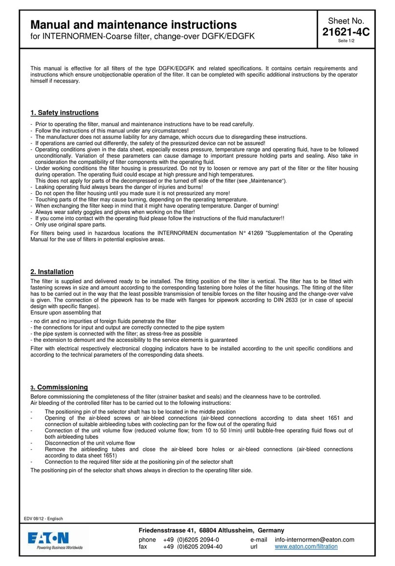
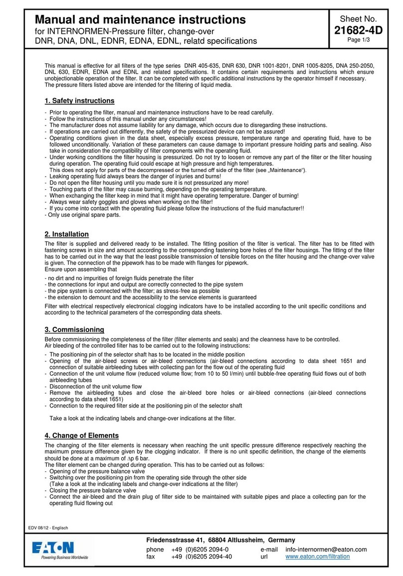
  9. Eaton DCF 400 Owner's manual

Eaton DCF 400 Owner's manual

DOM0000018-EN
Revision
A
Semi-Auto Control Installation, Operation & Maintenance
Teflon®and Viton®are a trademarks of DuPont™. Nordel™ is a trademark of The Dow Chemical Company. Kynar®is a trademark of Elf Atochem North America, Inc.
Page 1 of 4
Description ............................................................................................. 1
Specifications......................................................................................... 1
Service Requirements ....................................................................... 1
Materials of Construction................................................................... 1
Connections....................................................................................... 1
Design Temperature.......................................................................... 1
Airborne Noise Emissions ................................................................. 1
Installation.............................................................................................. 1
Connect Air Supply............................................................................ 1
Connect Electrical Supply ................................................................. 1
Transportation ................................................................................... 2
Securing to Foundation ..................................................................... 2
Checklist............................................................................................ 2
Commissioning Procedure ................................................................ 2
Operation ............................................................................................... 2
Operational Modes................................................................................. 2
Filtering.............................................................................................. 2
Cleaning ............................................................................................ 2
Purging .............................................................................................. 2
Control Logic .......................................................................................... 2
Purge Sequence......................... Fehler! Textmarke nicht definiert.
System Faults............................. Fehler! Textmarke nicht definiert.
Troubleshooting ..................................................................................... 3
Symptoms.......................................................................................... 3
Possible Faults .................................................................................. 3
Description
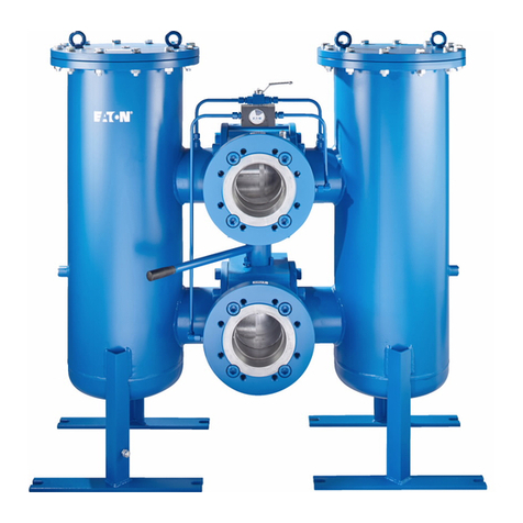
Each filter Station of a DCF filter system consists of a stainless steel
cylindrical filter screen sealed within a stainless steel filter housing.
Unfiltered process fluid enters the filter housing through the upper port.
The process fluid enters the inside of the filter screen from above and
the filtrate flows through the filter screen, exiting the filter housing
through the lower port. The filter screen traps filtered contaminants on
the inside of the filter screen. The contaminants are periodically
scraped off the surface of the filter screen by a cleaning disc which
travels up and down the surface of the screen. These contaminants are
deposited in a collection (purge) chamber in the bottom of the filter
housing where they are periodically purged out of the bottom port of the
filter housing.
Warning:
The use of Teflon®tape is not recommended
for all pipe connections. Teflon
®tape tends to break off
and clog orifices. Electrical supply voltage must match
the automation enclosure rating. Incorrect supply
voltage will cause damage and may cause injury.
To
prevent electrical shock, follow proper safe work
procedures when working on electrical circuits.
Specifications
This lists the general control specifications for a typical Mechanically
Cleaned semi automatic filter system.
Service Requirements
Electrical: 24V DC, 120V AC 50/60 Hz, Single phase supply.
Air: Minimum 60 PSIG (4 bar), Maximum 116 PSIG (8 bar) at 2.5 cfm
(70.79 L/min) clean, dry, non-lubricated air.
Materials of Construction
All welded and wetted materials are type 316/316L stainless steel. The
material selection for this vessel was based on the information provided
when the unit was ordered. It is the customer’s responsibility to ensure
material compatibility.
Connections
Air supply: ¼” NPTI (standard)
Design Temperature
Temperatures vary based on elastomer and cleaning disc materials.
Maximum temperature for lid and element elastomers: Viton®and
Teflon®400 °F (204 °C), Buna-N 220 °F (104 °C), EPT 300 °F
(149 °C)
Maximum temperature for cleaning disc materials: Polyethylene
180 °F (82 °C), Kynar®285 °F (140 °C), Teflon®400 °F (204 °C),
Urethane 175 °F (79 °C)
Airborne Noise Emissions
<70 dB(A) During normal operation
Installation
This document applies to the installation of the filter unit controls. See
additional instructions for the installation of the filter vessel.
Connect Air Supply
1. Install an air supply block valve, air filter and air supply bleed
valve (all customer supplied) before the solenoid valves.
2. Connect the air supply line to the air supply block valve (customer
supplied).
3. If not already assembled, connect the air lines from the solenoid
valves to the filter unit. On the cleaning disc solenoid valve,
connect port ‘B’ to the lower air port on the linear actuator.
Connect port ‘A’ to the upper air port on the linear actuator. When
the filter is ON, the solenoid valve is de-energized and the linear
actuator is retracted (at the top of the filter element). When the
linear actuator solenoid is energized, the cleaning disc is pushed
to the bottom of the filter housing.
4. Connect the purge valve solenoid port ‘B’ to the left port (when
facing the actuator with the indicator pointing up) on the purge
valve rotary actuator. Connect solenoid port ‘A’ to the right port
(when facing the actuator with the indicator pointing up) on the
purge valve rotary actuator. When the filter is ON, the solenoid
valve is de-energized and the purge valve is closed. When the
solenoid is energized, the purge valve opens.
Connect Electrical Supply
1. All wiring and power connections need to meet local electrical
code requirements.
2. No holes have been provided in the automation enclosure for
incoming wiring. A hole in the enclosure will need to be made in a
suitable location to receive incoming electrical wiring. Protect
Semi-Auto Control Installation, Operation & Maintenance
DOM0000018-EN, Revision A Page 2 of 4
internal components from metal chip and debris when making any
holes and connections.
Transportation
Move the filter system as close as possible to the installation site before
it is removed from the crate or skid. Position the filter frame on a
prepared, level foundation. Level the filter frame before it is anchored to
the foundation.
Securing to Foundation
Anchor the enclosure stand to the foundation using the three 5/8”
diameter anchor holes located at the base of the stand.
Checklist
Verify that all service connections are secure and meet local
codes.
Verify that the cleaning disc can be activated manually and
automatically if so equipped.
Verify that all lid bolts are tight. Do not over tighten. Damage may
occur to the lid and/or castle nuts.
Verify that the purge valve is closed.
Check that the purge discharge line is directed in a suitable
fashion to accept waste when purged.
Commissioning Procedure
1. Inspect the piping connections to the filter. Verify that the inlet
connection on the filter is connected to the pipe containing the
incoming process fluid. Repeat this procedure for the outlet and
purge connections.
2. All isolation valves to the filter should be closed. If there is a
bypass loop around the filter, that loop should be closed to
prevent back flushing dirty process fluid into the filter.
3. Open the isolation valve for the outlet piping.
4. If this filter was supplied with a control package, turn on the power
to the filter system controls.
5. Open the inlet isolation valve to allow approximately 25% of the
flow to reach the filter.
Notice:
Opening the inlet valve to the fully open
position without proper ramping will cause particles to
become wedged into the filter media. If this happens,
the filter media will have to be removed and cleaned
manually.
6. Over the next ½ hour, slowly introduce more of the flow until you
reach 100%. You may want to manually initiate a purge during
this time to ensure that piping debris is cleaned from the unit.
Operation
Warning
:Do not stroke cylinder when all the block
valves are closed. Pressure will increase inside the
filter housing and may create a hazardous situation.
1. The cleaning disc should stroke the element clean to keep the
differential pressure between the inlet and outlet of the filter below
15 PSID (103 kPa). Stroking too frequently will shorten the life of
all wear components.
2. The filter unit is supplied with a valve used to purge the
contaminants from the housing. This valve should be opened
before the collected contaminants exceed the purge chamber
volume and cause a differential pressure increase.
3. If the filter element is removed from the unit, avoid high pressure
washing from the inside of the element. This may force
contaminants into the filter media and cause permanent blockage
and/or element damage.
4. When first pressurizing the filter, it may be necessary to tighten
the lid/actuator rod seal. See
Figure 1. The viscosity of the
process fluid will determine
whether this is necessary. If
the seal begins to leak,
compress the seal by rotating
the packing wheel in one-sixth
of a turn increments. For
maximum seal life, do not use
excessive force to tighten the
packing wheel.
5. Always pressurize the unit
slowly on start up and watch
for leakage.
6. The unit is equipped with a plug in the lid for placement of
overpressure vent, for use as an air release and/or connection for
fluid filing of vessel.
7. Monitoring of the differential pressure between the inlet and outlet
pressures should be used to determine stroking and purging
rates. Normal operation should exhibit low differential pressure
that is maintained throughout.
Operational Modes
Filtering
Dirty process fluid enters thru the inlet port, is pushed thru the filter
screen where contaminants are removed and clean process exits thru
the outlet port.
Cleaning
The cleaning process occurs periodically during the filtering process.
As the dirty process fluid passes thru the filter screen, contaminants are
collected on the inside of filter screen. The cleaning disc scrapes the
length of the filter screen and pushes the contaminants into the purge
chamber.
Purging
The purging process occurs to remove contaminants collected in the
purge chamber. Once the cleaning disc assembly reaches the bottom
of the housing, the purge valve is opened, forcing the concentrated
contaminants collected in the purge chamber out of the filter.
Reference Sequence Diagram and Control Philosophy for complete
details.
Figure 1
Semi-Auto Control Installation, Operation & Maintenance
DOM0000018-EN, Revision A Page 3 of 4
Control Logic
Your control logic should be configured to allow the purge sequence to
occur by the following methods. Reference Sequence Diagram and
Control Philosophy supplied by EATON with the unit. The end user is
responsible for system function.
Troubleshooting
Symptoms
AActuator doesn’t operate properly
BPurge valve will not operate properly
CLeakage at lid seal
DLeakage where drive shaft enters lid
EReduction in flow rate or high differential pressure
FDrop in filtrate quality
Possible Faults
AActuator doesn’t operate properly
1No power
aCheck to see if the filter system is receiving adequate
power.
bCheck to see if the filter system is set to the proper
voltage.
cCheck all wiring connections.
2No air
aCheck to see if the filter system is receiving adequate
air.
bCheck for air leaks.
cCheck to see if the air bleed valve is closed and the air
block valve is open.
dCheck to see if the air lines are connected to the
correct ports.
3Actuator seals have been destroyed
aOrder a factory repair kit and replace the seals.
4Faulty solenoid valve
aCheck to see whether the manual override button on
the solenoid valve actuates the cylinder
5Cleaning disc not cleaning the filter screen
aInspect and clean the filter screen.
bInspect and replace the cleaning disc.
BPurge valve will not operate properly
1No power
aCheck to see if the filter system is receiving adequate
power.
bCheck to see if the filter system is set to the proper
voltage.
cCheck all wiring connections.
2No air
aCheck to see if the filter system is receiving adequate
air.
bCheck for air leaks.
cCheck to see if the air bleed valve is closed and the air
block valve is open.
dCheck to see if the air lines are connected to the
correct ports.
3Actuator seals have been destroyed
aOrder a factory repair kit and replace the seals.
4Faulty solenoid valve
aCheck to see whether the manual override button on
the solenoid valve actuates the cylinder
5Damaged purge valve
aReplace or rebuild purge valve
6Debris caught in purge valve
aRemove debris from purge valve
CLeakage at lid seal
1Loose lid nuts/bolts
aTighten lid/nut bolts to
2Dirty lid sealing surfaces
aClean lid sealing surfaces
3Damaged sealing surfaces
aRepair or replace filter station
4Worn lid O-ring
aRemove and replace with factory lid O-ring
DLeakage where drive shaft enters lid
1Damaged or worn drive shaft seal
aInspect and replace the drive shaft seal
EReduction in flow rate or high differential pressure
1Purge time too long
aDecrease purge timer setting
2Purge valve not functioning
aInspect and replace purge valve
3Dirty or damaged filter screen
aInspect and clean or replace filter screen
4Flow, viscosity or solids increase
aConsult factory
5Cleaning disc not cleaning
aInspect cleaning disc for wear and replace if necessary
FDrop in filtrate quality
1High differential pressure
aRefer to reduction in flow rate or high differential
pressure above
2Damaged filter screen O-rings
aRemove and replace with factory filter screen O-rings
3Damaged filter screen
aRemove and replace with factory filter screen
4Filter screen too coarse
aConsult factory for ability of filter system to accept a
finer screen retention. Remove and replace with
factory filter screen.
Semi-Auto Control Installation, Operation & Maintenance
DOM0000018-EN, Revision A Page 4 of 4
North America - HQ
China
44 Apple Street,
No. 7 Lane 280 Linhong Road,
Tinton Falls, NJ 07724
Changning District,
Toll Free: 800 656-3344
Shanghai 200335, China
(North America only)
Voice: +86 21 5200 0422
Voice: +1 732 212-4700
Europe/Africa/Middle East
Singapore
Auf der Heide 2
4 Loyang Lane #04-01/02
53947 Nettersheim, Germany
Singapore 508914
Voice: +49 2486 809-0
Voice: +65 6825 1668
lnternormen Product Line
Brazil
Friedensstrae 41
Rua Clark, 2061 – Macuco, Valinhos -
SP Brazil
68804 Altlussheim, Germany
13279-400
Voice: +49 6205 2094-0
Voice: +55 11 3616 8400
Begerow Product Line
An den Nahewiesen 24
55450 Langenlonsheim, Germany
Voice: +49 6704 204-0
lnternormen Product Line
WARRANTY
All products manufactured by Seller are warranted against defects in
material and workmanship under normal use and service for which such
products were designed for a period of eighteen (18) months after shipment
from our factory or twelve (12) months after start up, whichever comes first.
OUR SOLE OBLIGATION UNDER THIS WARRANTY IS TO REPAIR OR
REPLACE, AT OUR OPTION, ANY PRODUCT OR ANY PARTS OR
PARTS THEREOF FOUND TO BE DEFECTIVE. SELLER MAKES NO
OTHER REPRESENTATION OR WARRANTY, EXPRESS OR IMPLIED,
INCLUDING, BUT NOT LIMITED TO, ANY IMPLIED WARRANTY OF
MERCHANTABILITY OR FITNESS FOR A PARTICULAR PURPOSE. WE
SHALL NOT BE LIABLE FOR CARTAGE, LABOR, CONSEQUENTIAL
DAMAGES OR CONTINGENT LIABILITIES. OUR MAXIMUM LIABILITY
SHALL NOT IN ANY EVENT EXCEED THE CONTRACT PRICE FOR THE
PRODUCT.
If you are interested in ordering spare parts or having service
performed on your filter, please contact Customer Service.
Eaton reserves the right to change specifications, dimensions and model
designations without prior notice.
For more information, please e-mail us at
filtration@eaton.com
or visit www.eaton.com/filtration
© 2018 Eaton Corporation.
All rights reserved. All trademarks and registered trademarks are the property of their
respective owners. All information and recommendations appearing in this brochure
concerning the use of products described herein are based on tests believed to be reliable.
However, it is the user’s responsibility to determine the suitability for his own use of such
products. Since the actual use by others is beyond our control, no guarantee, expressed or
implied, is made by Eaton as to the effects of such use or the results to be obtained. Eaton
assumes no liability arising out of the use by others of such products. Nor is the information
herein to be construed as absolutely complete, since additional information may be
necessary or desirable when particular or exceptional conditions or circumstances exist or
because of applicable laws or government regulations.

This manual suits for next models

4

Other Eaton Water Filtration System manuals

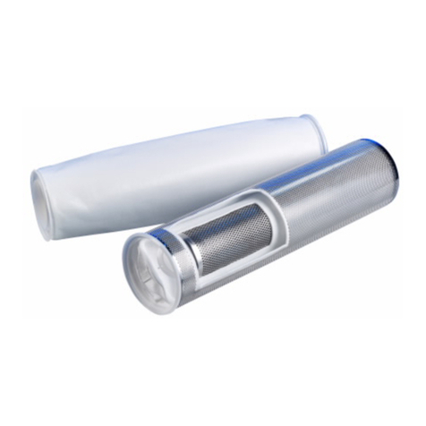
Eaton INTERNORMEN DNR Series Guide

Eaton

Eaton INTERNORMEN DNR Series Guide

Eaton MotoRx Series Manual

Eaton

Eaton MotoRx Series Manual

Eaton Cutler-Hammer 66A8060 User manual

Eaton

Eaton Cutler-Hammer 66A8060 User manual

Eaton DCF-3000 Owner's manual

Eaton

Eaton DCF-3000 Owner's manual

Eaton UM15 User manual

Eaton

Eaton UM15 User manual

Eaton 53BTX Owner's manual

Eaton

Eaton 53BTX Owner's manual

Eaton EDSF 1201-15001 Guide

Eaton

Eaton EDSF 1201-15001 Guide

Eaton MAXILINE MBF Series User manual

Eaton

Eaton MAXILINE MBF Series User manual

Eaton HCU2 User manual

Eaton

Eaton HCU2 User manual

Eaton DA/EDA 106 User manual

Eaton

Eaton DA/EDA 106 User manual

Eaton INTERNORMEN DGFK Guide

Eaton

Eaton INTERNORMEN DGFK Guide

Eaton INTERNORMEN DSF 1201-15001 Guide

Eaton

Eaton INTERNORMEN DSF 1201-15001 Guide

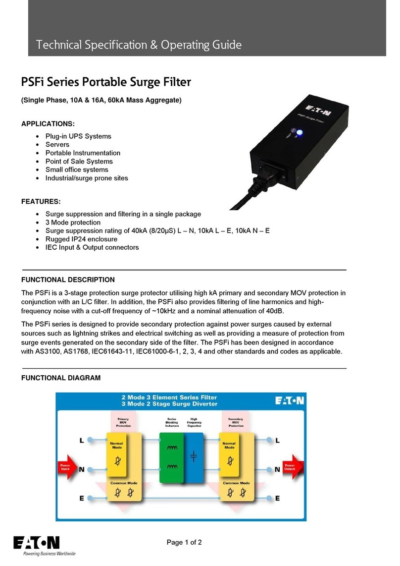
Eaton PSFi Series User manual

Eaton

Eaton PSFi Series User manual

Eaton LOEFFLER FILTRATION HAYFLOW User manual

Eaton

Eaton LOEFFLER FILTRATION HAYFLOW User manual

Eaton DWF 1505 User manual

Eaton

Eaton DWF 1505 User manual

Eaton 53 BTX User manual

Eaton

Eaton 53 BTX User manual

Eaton 30R User manual

Eaton

Eaton 30R User manual

Popular Water Filtration System manuals by other brands

Waterdrop WD-TSA-10 Installation

Waterdrop

Waterdrop WD-TSA-10 Installation

Vizion TAP-42x Series owner's manual

Vizion

Vizion TAP-42x Series owner's manual

Asutec ASME-500 Assembly instruction

Asutec

Asutec ASME-500 Assembly instruction

Brita PURITY 1200 Clean Extra Cartridge Replacement Instructions

Brita

Brita PURITY 1200 Clean Extra Cartridge Replacement Instructions

SY-KLONE RESPASC installation instructions

SY-KLONE

SY-KLONE RESPASC installation instructions

Pullman Holt 102 HEPA supplementary guide

Pullman Holt

Pullman Holt 102 HEPA supplementary guide

3M 3MPF101 Installation and operating instructions

3M

3M 3MPF101 Installation and operating instructions

Beko CLEARPOINT S040 Installation & operation instructions

Beko

Beko CLEARPOINT S040 Installation & operation instructions

Danfoss AHF 005 operating instructions

Danfoss

Danfoss AHF 005 operating instructions

Pentair OMNIFILTER IN-FF-500-SG-QC-4 Installation and operation manual

Pentair

Pentair OMNIFILTER IN-FF-500-SG-QC-4 Installation and operation manual

Grohe Blue Pure manual

Grohe

Grohe Blue Pure manual

Beko CLEARPOINT Series operating manual

Beko

Beko CLEARPOINT Series operating manual

SkyJuice SkyHydrant Set up and operating instructions

SkyJuice

SkyJuice SkyHydrant Set up and operating instructions

US Water Systems Flexx Oxi-Gen FX-150 owner's manual

US Water Systems

US Water Systems Flexx Oxi-Gen FX-150 owner's manual

Envirco MAC 10 Installation and service manual

Envirco

Envirco MAC 10 Installation and service manual

A/DA Nature Aquarium VUPPA II instructions

A/DA

A/DA Nature Aquarium VUPPA II instructions

Aqua Guard Invisipure user manual

Aqua Guard

Aqua Guard Invisipure user manual

Envirosource WAW-4012 user manual

Envirosource

Envirosource WAW-4012 user manual

manuals.online logo
manuals.online logoBrands
  • About & Mission
  • Contact us
  • Privacy Policy
  • Terms and Conditions

Copyright 2025 Manuals.Online. All Rights Reserved.