NOTES
TABULAR DATA
1. Measurement/Data Processing Systems: Primary - FChart: proprietary EAW software; Secondary - Brüel & Kjær 2012.
2. Microphone Systems: Earthworks M30; Brüel & Kjær 4133
3. Measurements: Dual channel FFT; length: 32 768 samples; sample rate: 48 kHz; logarithmic sine wave sweep.
4. Measurement System Qualication (includes all uncertainties):SPL: accuracy +/-0.2 dB @ 1 kHz, precision +/-0.5 dB 20 Hz to 20 kHz, resolution 0.05 dB; Frequency: accuracy +/-1 %, precision +/-0.1
Hz,resolutionthelargerof1.5Hzor1/48octave;Time:accuracy+/-10.4μs,precision+/-0.5μs,resolution10.4μs;Angular:accuracy+/-1°,precision+/-0.5°,resolution0.5°.
5. Environment: Measurements time-windowed and processed to eliminate room effects, approximating an anechoic environment. Data processed as anechoic or fractional space, as noted.
6. Measurement Distance: 7.46 m. Acoustic responses represent complex summation of the subsystems at 20 m. SPL is referenced to other distances using the Inverse Square Law.
7. Enclosure Orientation:Forbeamwidthandpolarspecications,asshowninMechanicalSpecicationdrawing.
8. Volts: Measured rms value of the test signal.
9. Watts:Peraudioindustrypractice,“loudspeakerwatts”arecalculatedasvoltagesquareddividedbyratednominalimpedance.Thus,thesearenotTrueWattunitsofenergyasdened
by International Standard.
10. SPL: (Sound Pressure Level) Equivalent to the average level of a signal referenced to 0 dB SPL = 20 microPascals.
11. Subsystem: This lists the transducer(s) and their acoustic loading for each passband. Sub = Subwoofer, LF = Low Frequency, MF = Mid Frequency, HF = High Frequency.
12. Operating Mode:Userselectablecongurations.Betweensystemelements,acomma(,)=separateamplierchannels;aslash(/)=singleamplierchannel.DSP=DigitalSignalProcessor.
IMPORTANT:Toachievethespeciedperformance,thelistedexternalsignalprocessingmustbeusedwithEAW-providedsettings.
13. Operating Range: Range where the processed Frequency Response stays within -10 dB SPL of the power averaged SPL within this range; measured on the geometric axis. Narrow band
dips are excepted.
14. Nominal Beamwidth: Design angle for the -6 dB SPL points, referenced to 0 dB SPL as the highest level.
15. Axial Sensitivity: Power averaged SPL over the Operating Range with an input voltage that would produce 1 W at the nominal impedance; measured with no external processing on
the geometric axis, referenced to 1 m.
16. Nominal Impedance: Selected 4, 8, or 16 ohm resistance such that the minimum impedance point is no more than 20% below this resistance over the Operating Range.
17. Accelerated Life Test:MaximumtestinputvoltageappliedwithanEIA-426Bdenedspectrum;measuredwithrecommendedsignalprocessingandRecommendedProtectionFilter.
18. Calculated Axial Output Limit: Highest average and peak SPLs possible during the Accelerated Life Test. The Peak SPL represents the 2:1 (6 dB) crest factor of the Life Test signal.
19. High Pass Filter: This helps protect the loudspeaker from excessive input signal levels at frequencies below the Operating Range.
GRAPHIC DATA
1. Resolution:Toremoveinsignicantnedetails,1/12octavecepstralsmoothingwasappliedtoacousticfrequencyresponsesand1/3octavecepstralsmoothingwasappliedtothebeamwidthand
impedance data. Other graphs are plotted using raw data.
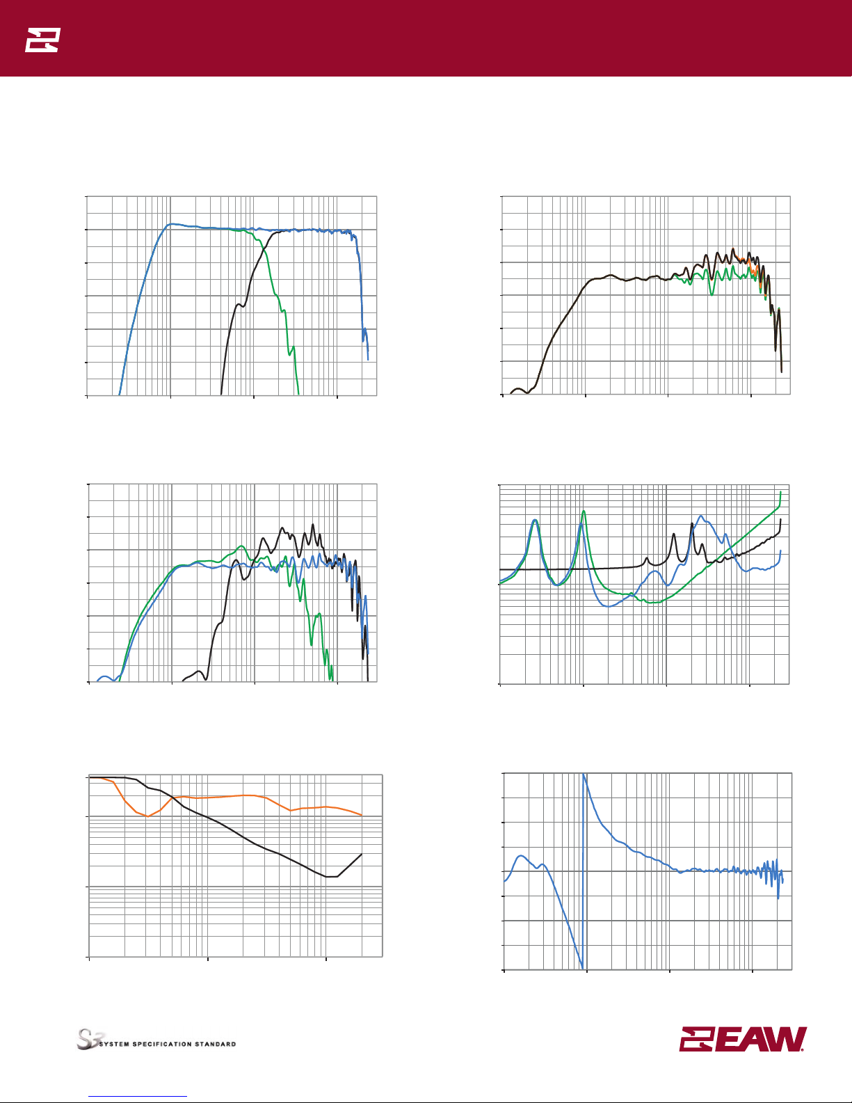
2. Frequency Responses: Variation in acoustic output level with frequency for a constant input signal. Processed: normalized to 0 dB SPL. Unprocessed inputs: 2 V (4 ohm nominal impedance), 2.83 V (8
ohm nominal impedance), or 4 V (16 ohm nominal impedance) referenced to a distance of 1 m.
3. Processor Response: The variation in output level with frequency for a constant input signal of 0.775 V = 0 dB reference.
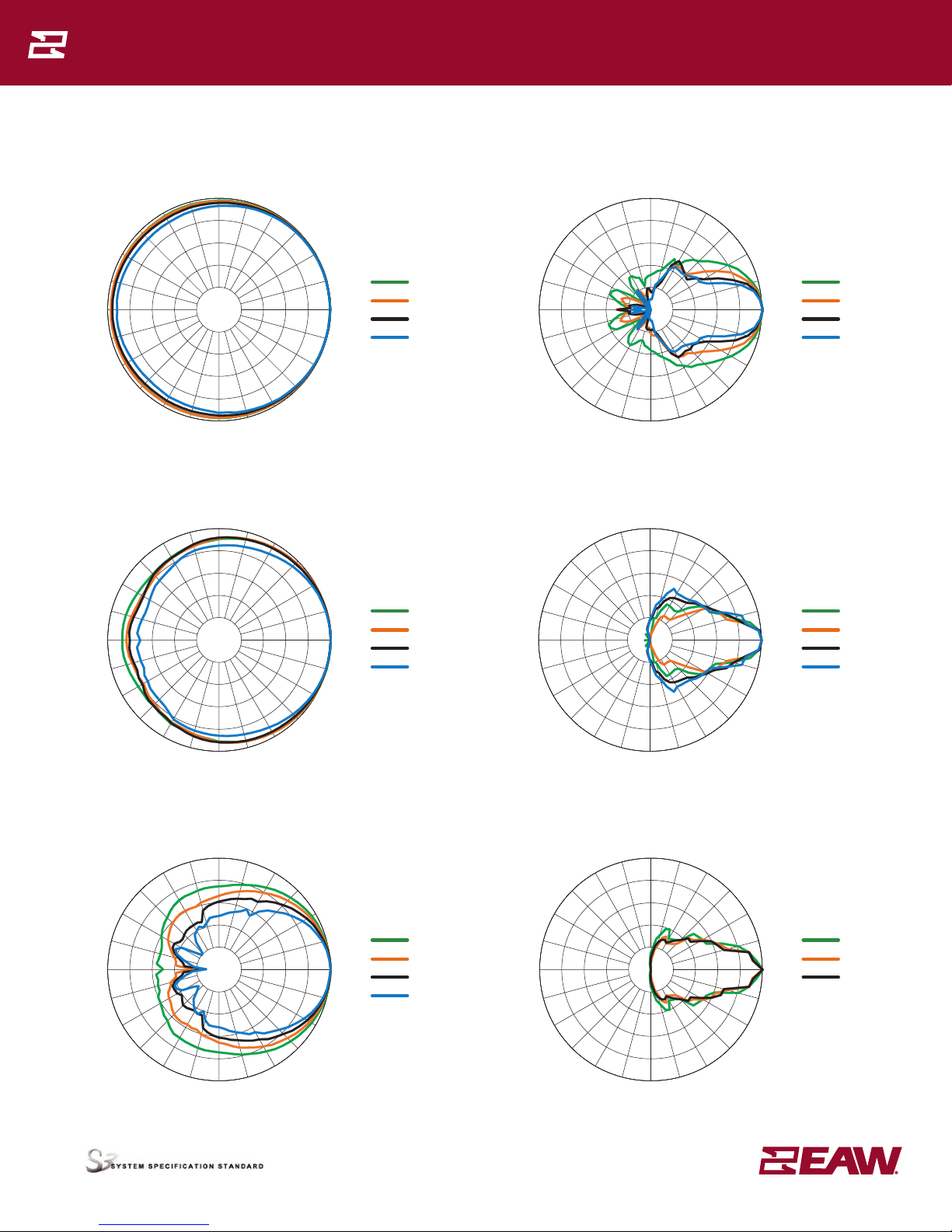
4. Beamwidth:Averageangleforeach1/3octavefrequencybandwhere,startingfromtherearoftheloudspeaker,theoutputrstreaches-6dBSPLreferencedto0dBSPLasthehighestlevel.Thismethod
means the output may drop below -6 dB SPL within the beamwidth angle.
5. Impedance: Variation in impedance magnitude, in ohms, with frequency without regard to voltage/current phase. This means the impedance values may not be used to calculate True Watts (see 9 above).
6. Polar Data: Horizontal and vertical polar responses for each 1/3 octave frequency band 100 Hz to 16 kHz or Operating Range.
LEGEND
HPF: High Pass Filter for crossover –or– Recommended High Pass Filter.
LPF: Low Pass Filter for crossover.
LF/MF/HF: Low Frequency / Mid Frequency / High Frequency.
AMP: User Supplied Power Amplifier –or– Integral Amplifier for NT products.
XVR: Passive LPFs, HPFs, and EQ integral to the loudspeaker.
EAW Focusing: Digital Signal Processor capable of implementing EAW Focusing.
JFL213 Specifications
Eastern Acoustic Works • One Main Street • Whitinsville, MA 01588 • tel 800 992 5013 / 508 234 6158 • fax 508 234 8251 • www.eaw.com
August 2012Part Number: RD0732 Rev 100EAW products are continually improved. All specications are therefore subject to change without notice.
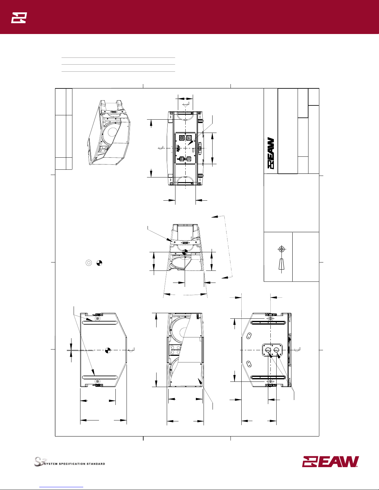
INPUT PANEL
REV: DESCRIPTION:
REVISIONS
A00 NEW ISSUE PER ECOWHT8897 MJC
DWG SPEC/INPUT JFL213
SCALE:
2038890-SD
MJC 09/14/11
DRAWING NUMBER:
DATE:
DRAWN BY:
1 of 1
1:1
REV:
A00
LOUD TECHNOLOGIES INC, ALL RIGHTS RESERVED
ONE MAIN STREET, WHITINSVILLE, MA 01588 USA
LOUD Technologies Inc.
TITLE:
SHEET:
ADOBE ILLUSTRATOR
BI-AMP
SINGLE-A MP
PIN 1
PIN 1
PIN 2
PIN 2
PIN 1 LF
NC
NC
LF
PIN 1
PIN 2 HF
HF
PIN 2
BI-AMP
SINGLE-A MP
PIN 1
PIN 1
PIN 2
PIN 2
PIN 1 LF
NC
NC
LF
PIN 1
PIN 2 HF
HF
PIN 2
HF SHADING
MULTI BOX
SINGLE BOX
LONG THROW
BI-AMP
SINGLE-AMP
OPERATING MODE
JFL213
JFL213 = 30 KG / 65 LB
JFL213 RIGGINGWORK ING LOAD LIMIT (WLL): FIVE(5)
JFL213 IN SUCCESSION. 148 KG / 325LB
FAILURE TO FOLLOW MANUFACTURER’S
INSTRUCTIONS CAN RESULT
IN DAMAGE, INJURY, OR DEATH.
DESIGNED IN WHITINSVILLE, MA, USA. MANUFACTUREDIN CHINA. ©2012 LOUD
TECHNOLOGIES, INC. “EAW” IS A REGISTEREDTRADEMARK OF LOUD TECHNOLOGIES,INC.
THIS PRODUCT HAS M10 MOUNTING POINTS. SEE OWNER’S MANUAL.
REVISION
SERIAL NUMBER
N
L
T
4
M
P
N
L
T
4
M
P
SIGNAL DIAGRAM
DSP
EQ
DELAY
HPF/LPF
OR
“EAW FOCUSING”
AMP
2-Way, Bi-Amp (LF, HF)
AMP
HF
LF
HPF
2-Way, Single-Amp (LF/HF)
AMP XVR
HF
LF