FlexRadio Systems SDR-1000 User manual

TM
FlexRadio Systems 2003 Page 1
SDR-1000/SDR-Console Troubleshooting Guide
This guide is intended as a companion to the SDR-1000 Hardware Manual and the SDR-
Console Installation and Quick Start Guide. It addresses common installation and
configuration pro lems and their possi le solutions. Please read the appropriate sections
of the a ove referenced manuals for more detail on these topics.
Relays Don’t Click When SDR-Console Software Loads
Operational Description: The SDR-1000 uses a set of four 8- it latches for controlling
the relays and DDS. When the unit is powered on, these latches are in an unknown state.
The SDR-Console should e loaded after powering on the radio for the first time. This
will reset all of the relays and the DDS to a known state. Pull down the ottom of the
SDRConsole form to reveal a Reset utton that can e used after software is loaded.
Probable Causes:
1. Parallel ca le does not have 25 conductors – The ca le must e a 25 conductor
straight through ca le with a DB-25P on each end. Some ca les may have 25 pin
connectors ut less than 25 conductors. The ca le should e the shortest availa le
and in no case longer than 6 feet in length. Caution: most flat cables do not
work in this application.
2. Parallel port ase address not set properly – For the radio to function, the ase
address must e correctly set on the Setup Options/General ta under PIO Base
Address. The ase address may e located y finding the first (lowest)
hexadecimal num er under Setting column on the Resources ta under the Printer
Port (LPT?) Properties, which may e found in the Windows Device Manager.
3. Shorts caused y metal spacers or washers – Do not use metal spacers or washers
etween the oards. They can short one of the power supplies to ground.
However, you can safely use metal screws on top of the BPF oard to screw into
the nylon spacers elow. You should place a set of four nylon washer and 3/8”
nylon spacer com inations etween the BPF and TRX oards, and etween the
TRX and PIO oards respectively.
4. Power supply does not handle sufficient current – The SDR-1000 can pull as
much as 1.25A efore reset and will normally draw 600-700mA in receive mode.
Place a current meter in line with the power supply to see that it is drawing the
600-700mA after reset. This is a good general indicator to tell if the radio is
working properly.
Relays Reset but Operation is Intermittent
Operational Description: See the previous Operation Description. Capacitive loading
on the parallel port ca le as well and insufficient drive from the parallel port itself can
adversely affect relia ility of the signals that control the SDR-1000 latches. This can
cause the DDS to tune to random frequencies and/or the relays to operate erratically.

TM
FlexRadio Systems 2003 Page 2
Probable Causes:
1. Ca le is too long – Use the shortest 25 conductor parallel port ca le you can find.
Under no circumstance should it e longer than 6 feet (1.8m) and less is
prefera le. The ca le should also e shielded. Caution: most flat cables do not
work in this application.
2. Parallel port drive insufficient – In some cases, the parallel port itself may e at
fault on some of the clone chips. Check the DC voltage on the parallel port data
lines (X1-1 to X1-9). Active high lines should e at +5VDC potential. Low
voltage drive can cause erroneous data to e sent to the DDS so that it looses it
synchronization. Try a different computer or add a new parallel port card to your
system.
Note: If the DDS is running properly, the radio will draw just under 700mA (400mA
with the switching regulator at IC5) in receive mode depending on the frequency of
operation. With the RFE oard installed, current drain will e just over 800mA. A very
low current could mean that the DDS is not running. A high current, near 1A or more
typically means that the radio is not eing reset properly.
he Radio Resets but I Don’t Hear Any Signals
Operational Description: The SDR-Console uses the Windows Multimedia Mixer to
control the ase and audio input and output from and to the SDR-1000 respectively. The
mixer controls may e accessed y dou le clicking on the speaker icon in the Windows
system tray or through the Windows Control Panel. There are two control panels:
normally called Volume (or Play ack) Control and Recording Control. The SDR-
Console uses the Recording Control to input signals through the Line In and Microphone
connectors on the sound card. It then processes the signals and sends the output to the
Wave control on the Volume Control panel.
Controls on the Volume Control panel connect sounds directly from their respective
inputs to the Speaker output Destination through the Wave Output control. This means
that signals originating from this control panel cannot e heard or processed y the SDR-
Console software. They are passed directly though y the operating system to the
Speaker/Line outputs. The Speaker/Line output is used y the SDR-1000 as ase and
transmit signal and therefore any signal coming through the Volume Control panel will
e placed directly on the air in unfiltered, dou le side and suppressed carrier mode. For
this reason it is important that all controls on the Volume Control panel e muted except
for the Wave and Master Volume controls. If the Line In and Microphone controls are
not muted here, they will cause an echo effect on receive or transmit audio respectively.
Controls on the Record Control panel route signals to the Wave Input Destination, which
is used y the SDR-Console software to capture the incoming digitized signals. These
signals are processed and routed to the Wave Output control on the Volume Control
panel to e sent to the Speaker Destination. This is true for oth receive and transmit
modes. The only difference is that the Record Control Source is switched etween the

TM
FlexRadio Systems 2003 Page 3
Line In and Microphone for the respective TR modes. For more information on the
operation of the sound card mixer read, “Making a Sound Card Work for You,” Bo
Freeth, G4HFQ, QEX, May 2001.
There are four configurations of the Windows Multimedia Mixer for Recording: Mux,
Mixer, Multiple Mute, and Multiple Select. All ut Multiple Select are currently
supported y SDR-Console. The software attempts to determine the mixer type and then
sets most of the controls to their proper settings. Here are the characteristics of the four
types:
• MUX – The input to the Recording Control allows only one input to e selected at
a time usually with a pull down select ox. It may also have select oxes at the
ottom of each control ut only one may e selected at a time. The Turtle Beach
Santa Cruz card uses a MUX type Record mixer.
• Mixer – The Mixer panel may have Select check oxes at the ottom of each
control. For proper operation only the desired control should e checked for the
respective TR mode – line-in for receive and microphone for transmit.
• Multiple Mute – SoundBlaster AWE32 and AWE64 cards typically have this type
of mixer. Each control on the Record Control has a mute check ox. This means
that for proper operation all controls must e muted except for the desired control
– line in for receive and microphone for transmit.
• Multiple Select – We have not seen this type of mixer so we can’t say what it
looks like. It is documented in the Microsoft mixer information. If you get the
error message: “Una le to determine the Record Source Mixer type," please
report it to FlexRadio Systems.
Probable Causes:
1. Make sure you are using one of the officially supported sound cards that are
listed on the Specifications Page of the Fle Radio Systems website and in the
SDRConsole Installation and Quick Start Guide. These are the ONLY cards
that we guarantee will work with the SDRConsole software. Use of other
cards is at your own risk.
2. Check all ca les according to the SDR-100 Hardware Manual instructions.
3. Read the SDR-Console Installation and Quick Start Guide for instructions on how
to install and use the software.
4. MUX or Mixer type Record Controls not selected properly – You have not
correctly set up the Input Mixer Selection on the SDR-Console Setup
Options/General ta . Open the Recording Control as descri ed a ove. O serve
the selected input as you press the up/down arrows on the Line In Record ID
control. Find the ID num er of the control that corresponds to the Microphone
(versions after v1.0.0 will allow you to directly set the Microphone ID with the
Mic In Record ID). Once you know the Microphone ID, dial it into the Mic In
Record ID using its respective up/down arrows. Next, find the Line In ID num er
using the Line In Record ID again and leave it with the Line In control selected.
Press OK or Apply to save the settings.

TM
FlexRadio Systems 2003 Page 4
5. Multiple Mute or Multiple Select – Notify FlexRadio Systems if you have a
pro lem with these types of mixers.
6. Bad audio ca le or incorrect connection – Read the installation section of the
SDR-1000 Hardware Manual to determine that you have correctly installed all
ca les. Check continuity of ca les you may have made yourself.
7. Master Mute on sound card mixer stays on – This is pro a ly due to a pro lem
with the PTT appearing to e engaged. This may cause the SDRConsole to cycle
in and out of transmit very quickly. The software mutes the Master Volume when
transitioning etween RX and TX and ack again. To see if this is the pro lem
you can check the Disa le PTT ox on the SetupOptions>Transmit ta . If this
fixes the pro lem refer to the topic elow, “Radio stays in transmit after releasing
the PTT utton.” It is also a possi ility that the parallel port ca le is not
connected properly.
8. Connectors not properly mated etween oards – It is important to make sure that
all connectors etween the BPF, TRX and PIO oards are properly mated. or
example if J2 on the BP board is not mated with J4 on the TRX board, signals
will be very weak.
9. Confirm that that the oscillator at QG1 is fully seated in the pin socket connectors.
You may also see a very high noise floor if the oscillator is not properly seated.
It is possi le to confirm proper operation of the mixer setup without the SDR-1000
hardware present. Simply connect an audio signal generator to the line input of the sound
card. Turn on the SDR-Console and set the mode to SPEC (Spectrum). This will display
the entire 40KHz andwidth of the receiver. If you have properly configured the mixer
as descri ed a ove you will e a le to see and hear a 1KHz signal from the audio
generator. You can move the frequency and you will see it move up and down the
spectrum. It will e displayed as a dou le side and suppressed carrier signal.
RFE Just Installed - Now Signals Weak and ransmit Power Low
Operational Description: The RFE requires the fa rication of a 10-pin extension
connector to go etween the BPF and RFE oard. The connector is fa ricated from ½ of
a 20-pin wire wrap socket. The original specification was to cut the pins to ¼ inch
(6.25mm). If the pins are any longer than this, they may short to the PCB elow, causing
the BPF relays to malfunction. It is unlikely that this will cause permanent damage ut
the radio will not function properly. The installation instructions have now een
modified to specify a length of 3/16 inch to allow more clearance for the pins.
I Am Receiving Signals But Cannot Null the Image
Operational Description: The SDR-1000 and SDR-Console together use Quadrature
Sampling to detect and modulate signals of all types. This means that J1 and J3 require
stereo (I and Q) inputs and outputs respectively from the sound card. The signals must e
of approximately equal magnitude and 90 degrees out of phase in order for the radio to
function properly. If one of the channels is not operating properly or you have
inadvertently connected the radio to the mono microphone input, it will e impossi le to

TM
FlexRadio Systems 2003 Page 5
remove the image and some modes will not operate. A further result will e a dou ling
of the noise power (3dB) in the receiver.
Probable Causes:
1. Review the Image Reject Alignment section in the SDRConsole Installation and
Quick Start Guide.
2. Bad or intermittent audio ca le or connector – Make sure that you have a properly
shielded, stereo, ca le and connector. Check continuity and short circuits, tip-to-
tip, ring-to-ring, and shield-to-shield. Make sure that the plugs are FULLY
engaged on oth ends of the ca le. If you are using the SDR1K-ENC enclosure,
make sure that the ack panel is seated all the way against the PC oard stack. If
the panel is not seated properly, it may prevent the connector from going all the
way into the jack. Note: A bad cable or a connector that is not fully engaged is
the VIRTUALLY ALWAYS the cause of image re ection problems.
3. Open the Recording Control mixer panel. Verify that the alance control is
centered. Any lack of alance on this control would prevent removal of the
image. Try moving the slider from side to side. If the signal goes away in one
direction, this indicates a pro a le ad ca le or connector that is not fully
engaged.
4. Poor quality sound cards may allow you to null the image, only to find that the
image rejection decreases only a few KHz away. This is due to amplitude
variance y frequency on the sound card itself. The only solution is a etter
sound card.
5. J1 on the TRX oard is connected to the microphone input – You cannot use a
mono microphone input to properly receive signals on the SDR-1000. A stereo
line input is required. With a mono input you can listen to signals ut you will
not e a le to remove the opposite side and image. The receive will also e
much noisier than normal.
6. You have no line in – Many note ook computers today do not have a line input.
In this case you will need to install a USB sound card such as the SoundBlaster
Extigy or MP3+.
It is possi le to test for proper operation of the SDR-1000 hardware independently. To
do so you will need to power up the hardware and load the SDR-Console software. Turn
the radio on with the On/Off utton and set it to the desired frequency with the INA gain
set to 26dB. Use a signal generator to apply a –10dBm signal near the VFO frequency
and o serve the ase and audio signals on the tip and ring of J1 on the TRX oard. If
you have tuned the radio correctly you should see audio frequency sine waves on the tip
and ring that are approximately equal in magnitude and 90 degrees out of phase. This
will tell you that the hardware is functioning properly.
he Radio is Receiving but Sensitivity Seems Low
Operational Description: Simply put, the SDR-1000 is dependant on having a high
quality sound card in order to function properly. Many sound cards and especially those
on the mother oard have low dynamic range, high noise floor, harmonic distortion, and

TM
FlexRadio Systems 2003 Page 6
clock jitter. All of these limit the effective dynamic range of the SDR-1000. Just
ecause a oard is called a 16- it oard does not mean that it has 16 usa le its of
dynamic range. Some cards may only have 12-14 usa le its. A true 16- it card will
have 96dB of dynamic range. You will loose 6dB of dynamic range for each it that is
not usa le.
Probable Causes:
1. If you just installed the RFE oard, read the section a ove titled, “RFE Just
Installed - Now Signals Weak and Transmit Power Low.”
2. The sound card does not have sufficient dynamic range to support the SDR-1000.
Refer to the officially supported sound cards that are named in the
SDRConsole Installation and Quick Start Guide and on the Specifications
page of the Fle Radio Systems website.
3. Some mixers have special effects (rever , etc.) that can significantly reduce the
dynamic range of the sound card. Make sure all effects are muted or turned off.
You want the sound card to have a completely flat input response for est
performance.
uning is Off Frequency
Operational Description: A 200MHz low jitter oscillator clocks the AD9854 DDS.
Frequency compensation is provided in the SDR-Console software to correct for
oscillator offset. A description of the procedure for offset compensation is covered
under the topic of Clock Oscillator Adjustment in the SDRConsole Installation and Quick
Start Guide.
Runtime Error 13 “ ype Mismatch”
Operational Description: International customers may experience this error message
when loading SDR-Console with the Windows operating system set for the local
language. This is ecause the SDR-Console uses the English fractional (decimal)
delimiter “.” for display and storage of frequency. Some countries use “,” or other
sym ols as fractional delimiters.
The current solution is to switch the OS to English using the Regional and Language
Options from the Windows Control Panel when running the SDR-Console. Windows
makes it fairly easy to switch ack and forth etween languages y placing the switch on
the task ar after you use it the first time.
If for some reason you open and close the SDR-Console in a language that does not have
the “.” delimiter, you will cause a very large frequency to e stored in the Windows
registry. This will cause the type mismatch error when you start SDR-Console. The only
solution is to delete the SDRConsole registry using regedit.exe. You will find the
SDRConsole folder under HKEY_CURRENT_USER\Software\VB and VBA Program
Settings\SDRConsole. Simply delete the folder, switch to English, and reload
SDRConsole. The defaults will then e restored.

TM
FlexRadio Systems 2003 Page 7
CPU Loading oo High – “Glitches” Heard in the Audio Output
Operational Description: Not all PCs are created equal. The CPU clock rate alone does
not tell the whole story. SDR-1000 performance will e directly affected y us, video,
sound card, and memory performance. Also, the num er of applications running will
affect the performance of the radio.
Probable Causes:
1. The SDRConsole uses increasingly sophisticated DSP software to perform all of
the modulation, demodulation, and filtering tasks. It is recommended that your
system use at least a 600MHz CPU with 256MB or more of RAM and a high
performance graphics su system. If you plan to run the VB6 IDE you will need
at least a 1GHZ machine to run in interpreted mode.
2. One of the most likely pro lems is that you have a slow on- oard video system.
These steal CPU and memory cycles to perform graphics tasks. Try adding a high
performance AGP video card such as that used y gamers. In many cases, this
will improve performance more than a higher speed CPU ecause of the graphics
overhead of the spectral display.
3. USB sound cards may add significant processor overhead as compared to PCI us
cards. If a USB sound card is required, it may e necessary to upgrade CPU
speed.
4. You may not have enough memory. Try increasing memory to 256MB or even
512MB.
5. Another good idea is to NOT allow Windows to manage the swap file. Set the
minimum and maximum sizes to the same num er, which effectively stops
Windows from resizing it on the fly. You can change this under the System
control panel, under Advanced Performance Options. A reasona le value for
Windows 2000 is a out 128MB. If possi le it should e located on the second
hard drive, if fitted.
6. Remove or turn off performance hogs like high color, animations, fancy screen
ackgrounds, shadowed cursor, XP style orders, active desktop, etc.
7. Try removing any unnecessary applications that are running in your system tray.
These eat up CPU cycles. You may also want to look at task manager to see what
other applications may e “lurking” around in the ackground. There are nice
utilities that help you manage these applications:
a. EndItAll -
http://www.pcmag.com/article2/0,4149,697,00.asp
.
StartupRun - http://www.we attack.com/Freeware/system/fwstartup.shtml
8. If you find that your system is still on the orderline in executing SDR-Console
you may want to try setting the OS to favor ackground tasks. Through the
Windows Control Panel go to the Advanced ta on the System Properties form.
Then select the Performance Settings and the Advanced ta . This will allow you
to set the Processor Scheduling to favor ackground tasks. DirectX is considered
y Windows to e a ackground task.

TM
FlexRadio Systems 2003 Page 8
Low or no power output on transmit
Operational Description: The SDR-1000 uses a TI OPA2674 (early units used the
OPA2677) Dual Wide and, High Output Current Operational Amplifier for the 1W
driver stage. As stated in the SDR-1000 Hardware Manual, the user should use caution
not to connect the amplifier into unknown or highly reactive loads. An open circuit or
highly capacitive load can cause the circuit to oscillate, resulting in a damaged part.
Also, the circuit requires approximately 0.5Vrms of ase and audio drive on J3 of the
TRX oard to reach the full 1W RMS output. Some sound cards may not have sufficient
drive to achieve this level of RF output. The RFE oard amplifier has higher gain (as
well as etter circuit protection) than the one on the BPF oard, there y allowing full
output with lower level sound cards.
Probable Causes:
1. Low power output in voice modes – Make sure that the RF control on the SDR-
Console is set to maximum (100%). If necessary, engage the Microphone Boost
on the Advanced utton of the mixer Record Control panel. This will
significantly increase the microphone channel gain. Make sure that the Wave
control on the Volume Control panel is set to maximum gain. If you still do not
have enough drive, measure the true RMS voltage on the Line/Speaker out
connector on the sound card. Make sure you are a le to drive the ~0.5V RMS
level required.
2. Low power in CW mode – The CWControls form on the Visual Basic
SDRConsole has its own “Level” control that sets the RF output in CW mode
only. Its control is independent of the PWR control on the front panel of the
SDRConsole. Make sure this control is set to 100% for full CW output.
3. No output – If an audio signal applied directly to J3 of the TRX oard does not
provide any RF output, it is likely that the OPA2674 is damaged and must e
replaced.
Radio Stays in ransmit After Releasing P Button
Operational Description: Status line S6 on the parallel port is used to tell the SDR-
Console software that the PTT line has een engaged. The 1K resistor, R9, is intended to
pull the signal line low when the PTT switch is not engaged, sending a high signal to S6.
Probable Causes: The 1K resistor may not provide a low enough impedance to ground
for some parallel ports. The solution is to attach another 1K resistor in parallel with R9
or replace it with a 500-ohm resistor. Newer units may have a 470 ohm resistor installed
already. If you still have pro lems, you can parallel a 200-270 ohm resistor. The voltage
at R9 should e elow 0.6V when PTT is not activated.

TM
FlexRadio Systems 2003 Page 9
Carrier is Very High on ransmit
Operational Description: The QSE, IC2 on the TRX oard, provides quadrature
sampling of the I and Q signals at the carrier frequency. Any DC im alance etween the
four phases will cause a high level of carrier output. The QSD is iased to 2.5VDC y
the voltage divider made up of R7 and R22. Worst-case carrier output with no
modulation should e –25dBm (-55dBW).
Probable Causes: The primary cause is a failure of IC2 on the TRX oard. Remove the
BPF oard for this test. Check the voltage at the common point etween R7 and R22 in
transmit mode. It should e 2.5VDC +/- 0.1V. If it is well outside of this range in
transmit mode, IC2 is damaged and must e replaced.
he LM7805 (IC5) Heat Sink on the PIO Board Gets Very Warm,
Possibly Causing the Radio to emperature Cycle.
Operational Description: The PIO oard uses LM7805 (IC5), 5V linear regulator, to
generate 5VDC from the 13.8VDC supply. IC9 and IC10 regulate the 5V supply down to
3.3V for powering the AD9854 DDS, which dissipates around 2W. All relays on the
BPF and TRX oard are also powered from the 5V supply. Although a linear supply
provides the lowest noise power solution, heat dissipation without forced air-cooling may
e a pro lem in some installations. Outside of an enclosure at room temperature, the heat
sink plate will run a out 60C. The DDS chip, IC4 on the TRX oard, will run over 70C
under the same conditions.
Probable Causes:
1. Metal jackscrews on the ottom of the PIO heat sink plate should mount directly
to a BARE metal on the enclosure with heat sink grease applied to the point of
contact. This will help significantly in the transfer heat into the enclosure.
2. Make sure there is proper airflow across the PC oard stack. It may e necessary
to install forced air-cooling. The SDR1K-ENC has provisions for the installation
of a 80mm fan.
he LCD Fonts are not Displayed on the SDR-Console
Operational Description: The SDR-Console frequency displays are est viewed with
the TBLCD font that may e retrieved from the link under the Software section on the
FlexRadio Systems Download page. Install the font according to the SDR-Console
Installation and Quick Start Guide.
Where are the SDR-Console Registry Entries?
Operational Description: All Setup Options as well as the state of the radio when
turned off are stored in the Windows Registry under:
HKEY_CURRENT_USER\Software\VB and VBA Program Settings\SDRConsole
If for some reason erroneous data gets stored in the Registry you can delete the
SDRConsole folder and it will e recreated on the next startup with the default values.

TM
FlexRadio Systems 2003 Page 10
How to est the Power Supply Voltages on the PIO Board?
Operational Description: The PIO oard contains regulators for 5VDC, two 3.3VDC
sources, 12VDC, and +/-15VDC. These supplies may e tested without the PIO oard
attached to the TRX oard. All measurements should be made on the bottom side of the
TRX board to prevent the possibility of shorting the power supply pins and causing
damage. The voltage measurements are as follows:
1. +12V regulated – J2 pin 9
2. +15V unregulated – J5 pin 2 (no load - approximately 18 to 21 volts) CAUTION,
DO NOT SHORT!!!
3. –15V unregulated – J5 pin 1 (no load - approximately –18 to –21 volts)
CAUTION, DO NOT SHORT!!!
4. +5V regulated – J5 pin 6
5. +3.3V regulated – J4 pin 9
6. +3.3V regulated – J4 pin 10
Other manuals for SDR-1000
2
Table of contents
Other FlexRadio Systems Transceiver manuals
FlexRadio Systems
FlexRadio Systems FLEX-5000A User manual
FlexRadio Systems
FlexRadio Systems Flex-3000 User manual

FlexRadio Systems
FlexRadio Systems FLEX-5000A User manual
FlexRadio Systems
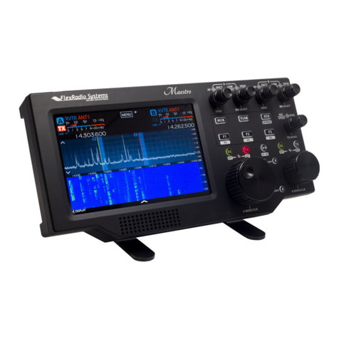
FlexRadio Systems FLEX-6000 Signature Series User manual
FlexRadio Systems
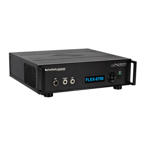
FlexRadio Systems FLEX-6000 Signature Series Quick user guide
FlexRadio Systems
FlexRadio Systems FLEX-5000C User manual

FlexRadio Systems
FlexRadio Systems FLEX-1500 User manual

FlexRadio Systems
FlexRadio Systems Flex-3000 User manual
FlexRadio Systems
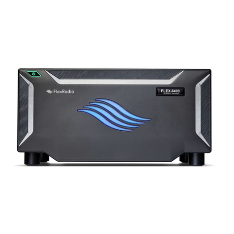
FlexRadio Systems FLEX-6400 Quick user guide
FlexRadio Systems
FlexRadio Systems FLEX-6700 User manual
