EBMA Hobby & Craft Wing Jig Instructions for use

Wing Jig
Construction Instructions
www.ebmahobby.co.uk
Introduction
The EBMA Wing Jig is produced in a combination of 3mm and 6mm M F. As such normal IY
woodwork procedures can be applied to them. The parts are cut by a laser cutter which results in
smoke marks on the surface of the wood. One side of the wood will have slight marks and the other
will be more pronounced. Some parts are symmetrical and you are therefore able to choose the
visual effect you wish. For asymmetrical parts if you wish to remove the smoke marks then fine
sandpaper may be used (use a sanding block, not just the paper on its own).
Where glue is required during assembly a good quality wood glue (PVA) should be used. When
wiping the excess away wherever possible wipe it towards the burnt edge as this marks less.
ry fitting components prior to gluing is highly recommended, i.e. compulsory! You should also
use an engineers’ square during construction to ensure that everything goes together absolutely
square.
Whilst parts are drying it can be handy to hold them in place with masking tape. This can be used
to help keep gaps closed.
© Copyright 2020 EBMA Hobby & Craft.

Construction
Shell
1. Place the 6mm thick piece with the burnt
side downwards. Glue the rear to this
ensuring that it is at right angles.
The rear is the longer piece with tabs on
all four edges.
2. Glue right hand side on.
3. Glue the left hand side on.
4. Glue the base on.
The base has tabs on three edges and one
straight edge.
© Copyright 2020 EBMA Hobby & Craft.

5. Turn the unit over and glue the top on.
Use the bolt heads to align the holes.
The shell is now complete, place it to
one side and allow it to dry.
Drawer
1. Glue the rear onto the base.
2. Glue the two sides on. Remove any
excess glue to ensure that the drawer will
run smoothly.
3. Glue the front on. Make sure it is a good
joint as you’ll be pulling the full weight
of the drawer with this.
The drawer is complete, but don’t put it
in the shell until everything is dry.
V-Shaped Fuselage Supports
1. There are two pairs of V-shaped fuselage
supports. They do not have to be used in
pairs and can be mixed or used
singularly as the shape of your aircraft
requires.
© Copyright 2020 EBMA Hobby & Craft.

2. Ensure that the base has the centre line
facing upwards and glue the support in
place.
Vertical Fuselage Supports
1. There are two of these supports that are
intended to work together to keep the
fuselage vertical and aligned with the
centreline of the jig.
2. Ensure that the centre-line on the base is
facing upwards and glue the two
diagonal supports to this. The horizontal
guides should face to the outside of the
support as shown.
3. Glue the front face on and allow to dry
before moving to step 4.
© Copyright 2020 EBMA Hobby & Craft.

4. Cut the more square neoprene in half and
stick each half to a support. On a cutting
surface place the neoprene face down
and using a sharp knife use the support
as a guide to cut away the excess
neoprene.
Long Fuselage Support
1. The long fuselage support is an extension
to the base unit. It may be fitted to the
front or rear of the unit to cater for larger
aircraft.
2. Ensure that the centre-line on the base is
upwards and glue the support to it.
Do not glue this to the longer piece or
you won’t be able to pack it away.
© Copyright 2020 EBMA Hobby & Craft.

3. Using the support from step 2 and the
base unit glue the two tab locators to the
long piece. The centre line on the long
piece should face upwards.
A small amount of glue between the top
surface of the long piece and the tabs is
all that is required.
o not glue the long piece or the tabs to
the base unit or the support from 2.
© Copyright 2020 EBMA Hobby & Craft.

Main Plane Supports
1. There are two large supports intended to
aid the orientation of the main wings, i.e.
to stop them rotating about their axis.
2. Glue the curved support to the base.
3. Glue the vertical into place.
4. For the diagonal support piece the longer
strip of neoprene needs to be cut in half
(lengthways) and then applied to the
support. Using a sharp knife and the
support as a guide remove the excess
neoprene. Then glue the support to the
vertical.
Wing Setting Guides
1. The wing jig comes with five pairs of
supports to set the angle of the wings or
stabilisers. The pair to use will depend
upon the geometry of the aircraft.
Each support consists of a base, curved
support and graduated vertical support.
It should be noted that there are three
sizes of curved support. Match the
curved piece to the size of the graduated
support ensuring that the curved piece
does not rise above the graduated one.
© Copyright 2020 EBMA Hobby & Craft.

2. Ensure that the line on the base is facing
upwards. Glue the curved support to the
base and then the graduated support to
both the curved and base pieces.
Using the Jig
olding the Fuselage
1. It is important that the fuselage is held
centrally and vertically on the wing jig.
To aid this there is a centre line cut down
the middle of the jig. The two vertical
supports should be used along with the
calibrations front to back on the jig to
help hold the fuselage vertically.
2. Align the aircraft fuselage along the
centre line of the jig.
3. Slide the vertical supports in so that they
hold the model vertically. Use the
graduated markings on the jig to ensure
that the supports are symmetical about
the centre line.
Use the left to right lines to ensure that
the supports are perpendicular to the
centre line.
© Copyright 2020 EBMA Hobby & Craft.

4. For larger models use the extension piece
and one or more of the V supports. The
extension piece can move from side to
side so care will need to be taken that the
centre line is correctly aligned.
Elastic bands can be used around the
hooks of the supports to aid holding a
fuselage in place.
5. Here the fuselage for a 1:72 Revel
Wiking BV222 has been setup using the
vertical supports and one of the large V
supports on the extension piece.
© Copyright 2020 EBMA Hobby & Craft.

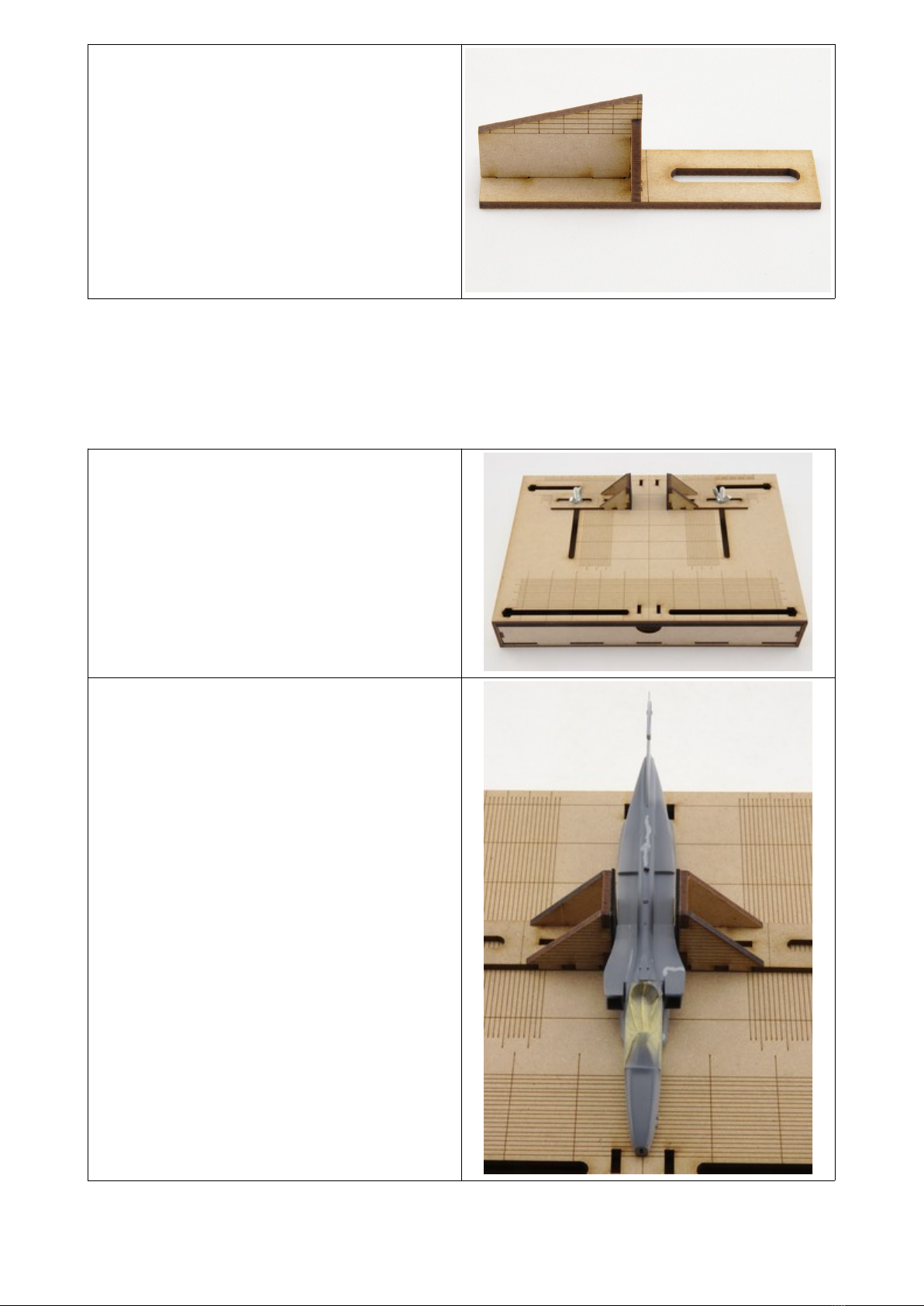
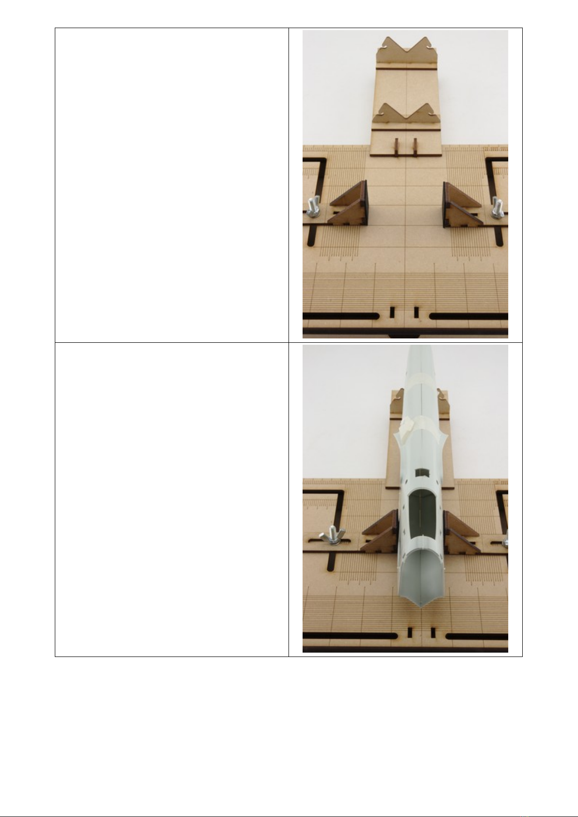
Setting the orizontal Stabilisers
1. With the fuselage held centrally and
vertically on the jig select the pair of
Wing Setting Guides that will support
the tail plane best. This largely
dependent upon the height of the
stabilisers above the jig.
2. Using a combination of the base marker
on the setting guides with the graduation
marks on the jig and also the graduation
marks on the setting guides set the angle
of the stabilisers.
For larger models it may be necessary to utilise the main plane section of the jig in order to set the
horizontal stabilisers.
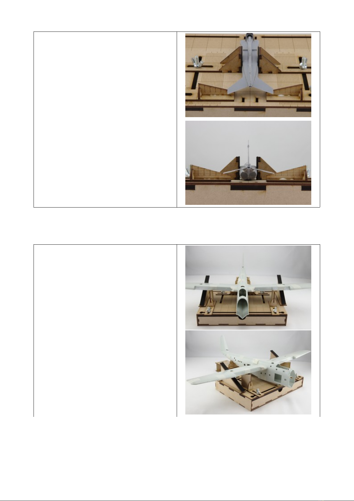
Setting the Main Plane
1. With the fuselage held centrally and
vertically on the jig select the pair of
Wing Setting Guides that will support
the wings best. This largely dependent
upon the height of the wings above the
jig.
2. Set one wing to approxiamately the
correct angle and then use the Main
Plane Supports to hold the wing at the
correct rotation to get a good joint with
the fuselage.
3. Set the second wing approxiamately the
same and check that the fuselage is still
correctly aligned.
4. Adjust the wing supports using the
graduation markings on the supports and
the base to help get both sides the same.
© Copyright 2020 EBMA Hobby & Craft.
Popular Toy manuals by other brands

Learning Resources
Learning Resources Jump 'N' Jam Jungle Use and care guide

SpringRC
SpringRC A3102 instruction manual

Nine Eagles
Nine Eagles SOLO PRO 130 operating instructions

Crayola
Crayola 4-in-1 Spiral Art Studio instruction manual

Fisher-Price
Fisher-Price N6224 instructions

roco
roco 42660 quick start guide