Ebro EBI IF-100 User manual

Interface
EBI IF-100/150//200/300

2
Deutsch
EBI IF-100/150/200/300
Inhaltsverzeichnis
Überblick 4
Sicherheitshinweise 6
Auspacken/Lieferumfang 8
Interface in Betrieb nehmen 10
Passende Antenne anschließen 12
Bei Bedarf: Netzteil anschließen 14
Bedeutung der Farbsignale 16
Interface-Betriebsarten (Modi) 18
Betrieb im Standard- Modus 20
Betrieb im Funkmodus 24
Was tun wenn… 28
...die Statusanzeigen dunkel bleiben? 28
...der PC „Interface nicht gefunden“ meldet?
28
...keine Verbindung zum Datenlogger
zustande kommt? 30
Reinigung und Pflege 32
Entsorgung 32
Elimination 33
Technische Daten 34
Zulassungen 34

1340-6001 1208 3
English
Français
Table of Contents
Overview 5
Safety Instructions 7
Unpacking/What is Included in the
Delivery 9
Operating the Interface 11
Connecting a suitable antenna 13
If required, connect a power supply unit
15
Meaning of the colored status display
lights 17
Interface operating types (modes) 19
Operation in wireless mode 25
What to do, if… 29
...the status display lights remain dark? 29
...the PC responds with “Interface not found”
29
...no connection is established to the data
logger? 31
Cleaning and Maintenance 33
Disposal 33
Technical Data 35
Approvals 35
Sommaire
Vue d’ensemble 5
Consignes de sécurité 7
Déballage / Fourniture 9
Mise en service de l’interface 11
Branchement de l’antenne adaptée 13
Au besoin : branchement d’une
alimentation secteur 15
Signification des signaux de couleur17
Modes d’exploitation de l’interface 19
Utilisation en mode standard 21
Utilisation en mode radio 25
Que faire quand… 29
...les indicateurs de statut ne s’allument pas
? 29
...l’ordinateur affi che le message « Interface
introuvable » ? 29
....il n’est pas possible d’établir la connexion
avec l’enregistreur de données ? 31
Nettoyage et entretien 33
Elimination 33
Caractéristiques techniques 35
Homologations 35

4
Deutsch
EBI IF-100/150/200/300
Überblick
Das Interface EBI IF-100/150/200/300 ist
ein Programmier- und Lesegerät der Serie
EBI 10/15/11 sowie ein Funkempfänger für
Datenlogger der Serie EBI 10.
Die Datenlogger EBI 10 werden per Funk
im Frequenzbereich 2,4 GHz programmiert
und ausgelesen.
Das Interface wird über ein Kabel mit einem
PC verbunden, von dort mit Hilfe einer
entsprechenden Software (z. B.
„Winlog.pro“) gesteuert und in der Regel
auch von dort mit Strom versorgt. Für den
Fall, dass der PC nicht genug Strom für das
Interface liefern kann, ist ein separates
Netzteil als Zubehör lieferbar.
Zum Programmieren und zum Auslesen der
aufgezeichneten Daten im Standardmodus
(siehe Seite 20) werden die Datenlogger in
die Ports des Interface gelegt. Zum
Empfang der Daten im Funkmodus (siehe
Seite 24) muss eine leistungsstarke
Antenne an das Interface angeschlossen
werden.
1.............Anschluss für Antenne
2.............Anschluss für USB
3.............Anschluss für Netzteil
4.............Ports für Datenlogger
Näheres zum Programmieren der
Datenlogger und zum Auslesen der
Daten entnehmen Sie bitte der
Gebrauchsanleitung Ihrer
Auswerte-software.

1340-6001 1208 5
English
Français
Overview
The EBI IF-100/150/200/300 interface is a
programming and reading device for EBI
10/15/11 series that also acts as a wireless
receiver for EBI 10 series data loggers.
These data loggers are programmed, and
with EBI 10 data is extracted from them, by
wireless in the 2.4 GHz frequency range.
The interface is connected by a cable to a
PC, from which it is controlled, using
suitable software (e. g. “Winlog.pro”), and
usually also supplied with power. If the PC
cannot supply enough power for the
interface, you can purchase a separate
power supply unit as an accessory.
To program the data logger and extract the
data recorded on it in standard mode (see
Page 21), the device must be placed in the
interface ports. To receive data in wireless
mode (see Page 25) a powerful antenna
must first be connected to the interface.
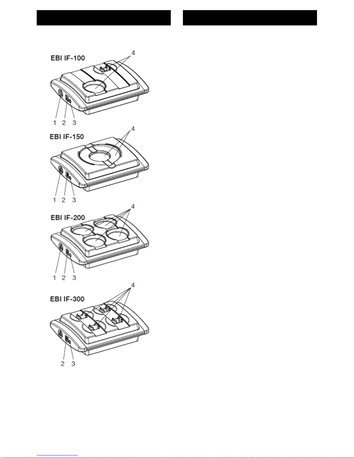
Structure of the interface:
1........... Antenna connection
2........... USB connection
3........... Power supply unit connection
4........... Data logger ports
For more information about how to
program the data logger, and how to
extract the data, please refer to the
user instructions for your read/write
program.
Vue d’ensemble
L’interface EBI IF-100/150/200/300 est un
dispositif de programmation de la série EBI
10/15/11 et de lecture, ainsi qu’un récepteur
radio pour les enregistreurs de données de
la série EBI 10, lesquels sont programmés
et lus par radio dans la plage de fréquences
des 2,4 GHz.
L’interface est reliée à un ordinateur via un
câble. Elle est pilotée à partir de cet
ordinateur à l’aide d’un logiciel (par ex.
Winlog.pro) et, en règle générale,
également alimentée en énergie à partir de
cette source. Dans le cas où l’ordinateur ne
serait pas en mesure de fournir
suffisamment d’énergie à l’interface, une
alimentation secteur séparée est disponible
en option.
En mode standard (voir page 21), les
enregistreurs sont reliés aux ports de
l’interface aux fi ns de programmation et de
lecture des données enregistrées. En mode
radio, une antenne puissante doit être
raccordée à l’interface pour garantir la
réception des données (voir page 25).
Caractéristiques de l’interface :
1............Connexion pour l’antenne
2............Port USB
3............Connexion pour l’alimentation
secteur
4............Ports pour les enregistreurs de
données
Pour plus de détails sur la
programmation des enregistreurs et sur
la lecture des données, veuillez-vous
référer à la notice d’utilisation de votre
logiciel d’exploitation.

6
Deutsch
EBI IF-100/150/200/300
Sicherheitshinweise
Verwenden Sie das Gerät nicht in
explosionsgefährdeten Bereichen.
Lebensgefahr!
Achten Sie darauf das Sie das Gerät
nicht so aufzustellen, dass das
Betätigen der Trenneinrichtung
(Netzgerät) erschwert wird!
Bringen Sie das Gerät nicht in eine
Umgebung, die heißer ist als 60°C!
Um Beschädigungen des Gerätes zu
vermeiden, schützen Sie es vor
direktem Kontakt mit Wasser.
Beachten Sie die Schutzklasse des
Gerätes (IP 20).
Das Interface sendet Funksignale im
Frequenzbereich 2,4 GHz aus.
Hierdurch können andere
technische Geräte unter Umständen
erheblich gestört werden!
Verwenden Sie das Interface daher
nur in Bereichen, in denen die
Funkstrahlung keine Gefahr
darstellt!

1340-6001 1208 7
English
Français
Safety Instructions
Do not use the device in areas in
which there is a danger of
explosions.
Danger of death!
Be sure to install the device in such
a way so that the disconnection of
power supply unit easily is
accessible.
Do not introduce the device into an
environment that is hotter than 60°C!
To avoid damaging the device,
protect it from direct contact with
water. Please note the device’s
protection class (IP 20).
The device emits wireless signals in
the 2.4 GHz frequency range. These
may cause significant interference
to other technical devices! For this
reason, only use the device in areas
where these wireless emissions do
not represent a risk!
Consignes de sécurité
N’utilisez pas l’appareil dans des
endroits soumis à des risques
d’explosion.
Danger de mort !
Soyez sûr d’installer le dispositif
dans une telle manière de sorte que
le débranchage de l’unité
d’alimentation d’énergie soit
facilement accessible.
Ne placez pas l’appareil dans un
environnement soumis à des
températures supérieures à 60 °C.
Afi n d’éviter d’endommager
l’appareil, évitez de le mettre en
contact direct avec de l’eau. Veillez à
respecter la classe de protection de
l’appareil (IP 20).
L’interface émet des signaux radio
dans la plage de fréquences des 2,4
GHz. Il est possible que cela
occasionne de sérieuses
perturbations pour d’autres
équipements techniques! Pour cette
raison, veuillez n’utiliser l’interface
que dans des endroits où cette
émission de signaux radio ne
constitue pas un danger!

8
Deutsch
EBI IF-100/150/200/300
Auspacken/Lieferumfang
Überprüfen Sie nach dem Erhalt die
Geräteverpackung und den Inhalt auf
Unversehrtheit. Überprüfen Sie
außerdem, ob der Inhalt der
Geräteverpackung Ihrer Bestellung
entspricht.
Lieferumfang
Im Lieferumfang sind folgende Teile
enthalten:
–Interface EBI IF-100/150/200/300
–USB-Kabel
–Stabantenne 5 dbi (Art.-Bez. AL
111), bei EBI IF-100/200
–diese Gebrauchsanleitung
–CD-ROM mit Treibersoftware
Daneben können in der Lieferung
verschiedene Zubehörteile enthalten
sein:
Beschreibung Bezeichnung
Draht-Antenne AL112
Auswertesoftware Winlog.x
Netzteil AL 120
Sollten Sie Grund zu einer
Beanstandung haben, nehmen Sie
bitte mit uns Kontakt auf. Unsere
Kontaktdaten finden Sie auf der
Umschlagrückseite.

1340-6001 1208 9
English
Français
Unpacking/What is Included in
the Delivery
Check the device packaging and contents
to ensure they are complete and
undamaged. You must also check that the
contents of the packaging match your order.
What is Included in the Delivery
The delivery includes these parts:
–EBI IF-100/150/200/300 interface
–USB cable
–rod antenna 5 dbi (Part Name AL 111),
only EBI IF-100/200
–these operating instructions
–CD-ROM with driver software
The delivery may also include various
accessories:
Description Name
Wire antenna AL 112
Evaluation software Winlog.x
Power supply unit AL 120
If you have any reason for complaint, do
not hesitate to contact us. Our contact
details are printed on the reverse of the
envelope.
Déballage / Fourniture
A réception des appareils, vérifi ez que
l’emballage et le contenu sont intacts.
Vérifiez également si le contenu de
l’emballage correspond bien à votre
commande.
Eléments contenus dans l’emballage
Les éléments suivants sont fournis dans
l’emballage :
–interface EBI IF-100/150/200/300
–cordon USB
–mât-antenne 5 dbi (Réf. pièce AL 111)
chez EBI IF-100/200
–la présente notice d’utilisation
–un CD-ROM avec les pilotes logiciels
Différents accessoires peuvent en outre
être fournis :
Description Désignation
Câble-antenne AL112
Logiciel d’exploitation Winlog.x
Alimentation secteur AL 120
Si vous souhaitez faire une réclamation,
n’hésitez pas à nous contacter. Nos
coordonnées se trouvent au verso de
l’enveloppe.

10
Deutsch
EBI IF-100/150/200/300
Interface in Betrieb nehmen
Die Inbetriebnahme des Interfaces
besteht aus vier Schritten:
1.) Interface über USB-Kabel mit PC
verbinden
2.) Passende Antenne anschließen
3.) Falls der PC nicht genug Strom
liefert: Netzteil anschließen
4.) Interface-Treiber auf dem PC
installieren
Interface mit PC verbinden
Im Lieferumfang des Interfaces befin-
det sich ein USB-Kabel. Dessen
Stecker mit dem rechteckigen
Querschnitt (Typ A) ist an den PC zu
stecken. Der Stecker mit dem
quadratischen Querschnitt (Typ B)
passt zur Buchse am Interface.
-Stecken Sie die Kabelstecker in die
jeweils passende Buchse am PC
und am Interface. Verwenden Sie
am PC eine High-Power-USB-
Buchse, sofern vorhanden.
Führen Sie diesen Vorgang mit
Gefühl aus und wenden Sie keine
große Kraft an. Die Stecker sind
verpolungssicher und passen nur in
einer bestimmten Ausrichtung in die
jeweilige Buchse.

1340-6001 1208 11
English
Français
Operating the Interface
Bringing the interface into operation
involves four steps:
1.) Connecting the interface to the PC
with a USB cable
2.) Connecting a suitable antenna
3.) Connecting a power supply unit
(only if the PC cannot supply
enough power)
4.) Installing the interface driver on
the PC
Connecting the Interface to the PC
The interface is supplied along with a
USB cable. Insert its plug (type A, with
rectangular cross-section) into the PC.
The square cross-section plug (type B)
fits the socket on the interface.
-Insert the ends of the cable plug into
the appropriate socket on the PC
and on the interface. We
recommend that you use a high-
power USB socket on the PC, if
present.
Take great care throughout this
procedure and do not use excessive
force at any point. The plugs are
polarized and only fi t into the
socket in one particular alignment.
Mise en service de l’interface
La mise en service de l’interface
s’effectue en quatre étapes :
1.) Reliez l’interface à l’ordinateur
via le cordon USB
2.) Branchez l’antenne adaptée
3.) Si l’ordinateur ne peut pas
fournir suffisamment d’énergie :
branchez l’alimentation secteur
4.) Installez le pilote de l’interface sur
l’ordinateur
Connexion de l’interface à
l’ordinateur
L’interface est livrée avec un cordon
USB. Branchez l’extrémité de section
rectangulaire (type A) de ce cordon sur
l’ordinateur. Branchez ensuite
l’extrémité de section carrée (type B)
sur le connecteur correspondant de
l’interface.
-Branchez les connecteurs de câble
aux emplacements correspondants
sur l’ordinateur et l’interface. Si
l’ordinateur en est équipé, utilisez
un port USB haute puissance.
Effectuez cette opération en douceur
et sans forcer. Les prises sont
protégées contre les inversions de
polarité et munies d’un détrompeur.

12
Deutsch
EBI IF-100/150/200/300
Passende Antenne
anschließen
Im Lieferumfang des Interfaces
befinden sich zwei Antennen, eine
Stab-Antenne und eine Draht-Antenne.
Die Stab-Antenne ist für den normalen
Betrieb (sowohl Standard-Modus als
auch Funkmodus) vorgesehen. Die
Draht-Antenne ist für Messungen in
Prozessen mit kritischen
Funkübertragungs-Eigenschaften (z. B.
in Dampfsterilisatoren, Autoklaven,
Öfen etc.) vorgesehen. Beide Antennen
besitzen ein Gewinde passend zur
Antennenbuchse des Interfaces und
werden alternativ auf die Buchse des
Interfaces geschraubt.
Ziehen Sie vor einem Wechsel der
Antennen den Netzstecker bzw. das
USB-Kabel vom Interface ab, so
dass die Statusanzeigen nicht mehr
leuchten.
Es dürfen aus Gründen der
Betriebssicherheit nur die von ebro
gelieferten Antennen an das
Interface angeschlossen werden.
-Schrauben Sie die Stab-Antenne
bzw. den Stecker der Draht-
Antenne an die Buchse des
Interfaces.
Führen Sie diesen Vorgang mit
Gefühl aus und wenden Sie keine
große Kraft an.

1340-6001 1208 13
English
Français
Connecting a suitable antenna
The interface is supplied along with two
antennae: one rod antenna and one
wire antenna.
The rod antenna is designed for normal
operations (in both standard mode and
wireless mode). The wire antenna is
designed to record measurements in
processes that have critical wireless
transmission attributes (e.g. in steam
sterilizers, autoclaves, ovens etc.).
Each antenna has a thread that fits into
the interface’s antenna socket.
Alternatively, they can be screwed into
the interface socket.
Before you change an antenna, pull
the power supply cable or the USB
cable out of the interface so that the
status display lights go out. To
ensure correct operation, you must
only connect antennae supplied by
ebro to the interface.
-Either screw the rod antenna, or the
wire antenna’s plug, into the
interface socket.
Take great care throughout this
procedure and do not use excessive
force at any point.
Branchement de l’antenne
adaptée
L’interface est livrée avec deux
antennes, un mât-antenne et un câble-
antenne.
Le mât-antenne est prévu pour une
utilisation courante (aussi bien en
mode standard qu’en mode radio). Le
mât-antenne est prévu pour les
mesures effectuées dans le cadre de
processus présentant des conditions
critiques de transmission par radio (par
ex. dans des autoclaves, des fours
etc.). Les deux antennes sont équipées
d’un filetage adapté à la bague de
l’antenne de l’interface et peuvent
également être vissées sur la bague de
l’interface.
Avant de changer les antennes,
retirez la prise ou le cordon USB de
l’interface, de sorte que les
indicateurs d’état ne soient plus
allumés. Pour des raisons de
sécurité d’exploitation, seules des
antennes fournies par ebro peuvent
être raccordées à l’interface.
-Vissez le mât-antenne ou la prise
du câble-antenne sur la bague de
l’interface.
Effectuez cette opération en douceur
et sans forcer.

14
Deutsch
EBI IF-100/150/200/300
Bei Bedarf: Netzteil
anschließen
Falls der PC über den USB nicht genug
Strom für den Betrieb des Interfaces
liefern kann, müssen Sie das Interface
mit einem eigenen Netzteil betreiben
(als Zubehör erhältlich). In diesem Fall
erscheint nach dem Anstecken des
Interfaces an den USB des PCs eine
entsprechende Meldung auf dem
Bildschirm.
Nur wenn diese Meldung erscheint,
benötigen Sie das Netzteil.
Verwenden Sie nur das von ebro
gelieferte Netzteil zum Betrieb des
Interfaces. Nur dieses hat die
erforderlichen technischen
Eigenschaften.
-Stecken Sie - falls benötigt –den
Netzstecker in die Netzsteckdose
und den Niederspannungsstecker in
die Buchse am Interface.
Sobald das Interface mit Strom
versorgt ist, leuchten alle Status-
Anzeigen des Interfaces blau.
Interface-Treiber installieren
Im Lieferumfang des Interfaces
befindet sich eine CD-ROM mit der
zugehörigen Treibersoftware. Neben
der Treibersoftware befindet sich auf
der CD-ROM auch die genaue
Anleitung zur Installation der Software.
-Wie Sie die Treibersoftware auf
Ihrem PC installieren, entnehmen Sie
bitte der Anleitung auf der CD-ROM.

1340-6001 1208 15
English
Français
If required, connect a power
supply unit
If the PC cannot supply enough power
along the USB cable to operate the
interface, you must use a separate
power supply to run the interface (this
is available as an accessory). In this
case, a message appears on screen
immediately after you plug the interface
into the PC’s USB port.
You will only need to attach a power
supply unit if this message appears.
Only use the power supply unit
supplied by ebro to operate the
interface. This is the only unit that
has the required technical
functionality.
-If necessary, insert the mains plug
into the mains socket and then
insert the low voltage plug into the
socket on the interface.
As soon as the interface is supplied
with power, all status display indicators
light up blue.
Installing the Interface Driver
The interface is supplied together with
a CD-ROM that holds the required
driver software. This CD-ROM also
contains precise instructions about how
to install the software.
-The instructions on the CD-ROM
will tell you how to install the driver
software on your PC.
Au besoin : branchement
d’une alimentation secteur
Si l’ordinateur ne peut pas fournir
suffisamment d’énergie pour permettre
l’utilisation de l’interface, cette dernière
doit être alimentée par sa propre
alimentation secteur (disponible en
option). Si tel est le cas, un message
correspondant s’affiche à l’écran
lorsque vous avez branché l’interface
sur le port USB de l’ordinateur.
L’alimentation secteur supplémentaire
n’est requise que si ce message
apparaît.
Utilisez exclusivement l’alimenta-
tion secteur fournie par ebro. Seule
cette interface présente les carac-
téristiques techniques requises.
-Si nécessaire, reliez la prise secteur
au secteur et la prise basse tension
à la bague de l’interface.
Dès que l’interface est alimentée en
énergie, les indicateurs de statut de
l’interface s’allument en bleu.
Installation des pilotes de l’interface
L’interface est livrée avec un CD-ROM
contenant les pilotes logiciels requis.
Le CD-ROM contient également les
instructions d’installation précises du
logiciel.
-Respectez les instructions fournies
sur le CD-ROM pour installer les
pilotes logiciels sur votre ordinateur.

16
Deutsch
EBI IF-100/150/200/300
Bedeutung der Farbsignale
Sobald das Interface mit Strom
versorgt wird, leuchten die Status-
Anzeigen an den Datenlogger-Ports. Je
nachdem, welche Funktion das
Interface gerade ausführt, ändern die
Status-Anzeigen ihre Farbe. Es
bedeuten:
blau Interface betriebsbereit
gelb Programmieren/Auslesen
des Datenloggers im
jeweiligen Port
grün Programmieren/Auslesen
erfolgreich
rot Programmieren/Auslesen
nicht erfolgreich
violett blinkend Funkmodus

1340-6001 1208 17
English
Français
Meaning of the colored status
display lights
The status display lights on the data
logger ports come on as soon as the
interface is supplied with electricity.
These lights change color, depending
on which function the interface is
performing. The colors have these
meanings:
blue interface ready for use
yellow program/extract data from
the data logger in the
particular port
green programming/data
extraction successful
red programming/data
extraction failed
flashing violet wireless mode
Signification des signaux de
couleur
Dès que l’interface est alimentée en
énergie, les indicateurs de statut
s’allument au niveau des ports des
enregistreurs. La couleur des
indicateurs de statut change selon la
fonction en cours d’exécution au niveau
de l’interface. La signifi cation des
différentes couleurs est la suivante :
bleu Interface prête à être
utilisée
jaune Programmation/lecture
de l’enregistreur sur le
port correspondant
vert Programmation/lecture
terminée avec succès
rouge Programmation/lecture
échouée
violet clignotant Mode radio

18
Deutsch
EBI IF-100/150/200/300
Interface-Betriebsarten
(Modi)
Das Interface kann in zwei
verschiedenen Betriebsarten (Modi)
eingesetzt werden:
–im Standard-Modus und
–im Funkmodus.
Beim Standard-Modus wird das
Interface dafür benutzt, um
Datenlogger zu programmieren oder
um alle im Datenlogger gesammelten
Daten auf einmal auszulesen. Hierbei
kann pro Port des Interfaces jeweils ein
Datenlogger programmiert oder
ausgelesen werden.
Im Funkmodus wird das Interface als
Funk-Empfänger eingesetzt. Hierbei
empfängt das Interface laufend die
Signale von Datenloggern, die
ebenfalls im Funkmodus arbeiten und
ihre Messdaten im Takt ihrer Messung
senden. Im Funkmodus können
Funksignale von bis zu 40
Datenloggern parallel empfangen und
verarbeitet werden.
Sie erkennen den Funkmodus des
Interfaces am violetten Blinken der
Status- Anzeigen.

1340-6001 1208 19
English
Français
Interface operating types
(modes)
The interface can be used in two
different operating modes:
–in standard mode and
–in wireless mode.
In standard mode the interface is used
either to program the data logger or to
extract all the data collected in the data
logger at once. In this way a different
data logger can be programmed, or
data can be extracted from it, on each
one of the interface’s ports.
In wireless mode the interface is used
as a wireless receiver. In this situation,
the interface continuously receives
signals from data loggers that are also
running in wireless mode and sending
measurement data as soon as they
record the measurements. When
operating in wireless mode the
interface can receive and process radio
signals from up to 40 data loggers at
the same time.
When the interface is running in
wireless mode, the violet status display
lights fl ash on and off.
Modes d’exploitation
de l’interface
L’interface peut être utilisée dans deux
modes différents :
–en mode standard ou
–en mode radio.
En mode standard, l’interface est
utilisée pour programmer des
enregistreurs de données ou pour
exploiter toutes les données
enregistrées en une fois. Dans ce
mode, il est possible de programmer ou
de lire un enregistreur de données par
port de l’interface.
En mode radio, l’interface est utilisée
en tant que récepteur radio. Dans ce
mode, l’interface reçoit en permanence
les signaux des enregistreurs de
données qui fonctionnent également en
mode radio et transmettent leurs
mesures au rythme où ils les
effectuent. En mode radio, les signaux
radio peuvent être reçus et traités en
parallèle sur 40 enregistreurs de
données.
Le mode radio de l’interface est
identifiable via la couleur violette
clignotante des indicateurs de statut.

20
Deutsch
EBI IF-100/150/200/300
Betrieb im Standard-
Modus
Im Standard-Modus wird das Interface
dafür benutzt, um Datenlogger zu
programmieren oder um alle im
Datenlogger gesammelten Daten auf
einmal auszulesen. Hierbei kann pro
Port des Interfaces jeweils ein
Datenlogger auf einmal programmiert
oder ausgelesen werden.
Um Datenlogger zu programmieren
oder auszulesen, gehen Sie
folgendermaßen vor:
-Bei Datenloggern in einer Silikon-
Schutzbox entfernen Sie zunächst
jeweils das Unterteil der
Silikonschutzbox.
-Legen Sie den Datenlogger mit der
Kunststoffseite nach unten in einen
freien Port des Interfaces.
-Starten Sie bei der
Auswertesoftware auf dem PC den
Programmier- bzw. den
Lesevorgang und folgen Sie den
Anweisungen auf dem Bildschirm.
Solange die Statusanzeige eines Ports
gelb leuchtet, läuft der Programmier-
bzw. Lesevorgang an dem jeweiligen
Datenlogger.
Leuchtet die Statusanzeige eines Ports
grün, dann war der Programmier- oder
Lesevorgang erfolgreich. Leuchtet sie
rot, war der Vorgang nicht erfolgreich.
max. 70°C
max. 70°C
max. 70°C
max. 70°C
This manual suits for next models
3
Table of contents
Other Ebro Recording Equipment manuals