Ebtron Advantage III Gold Series User manual

EBTRON • 1663 Hwy. 701 S., Loris SC 29569 • Toll Free: 800.2EBTRON (232.8766) • Fax: 843.756.1838 • Internet: EBTRON.com
Model GTM116-B
Installation Guide
Gold Series Thermal Dispersion Airflow Measurement Technology
Advantage III
Gold Series by Ebtron
Installation Guide
GTM116-B
“Plug & Play” Transmitter with Bleed Airflow Sensors,
Combination Ethernet Network Output and Dual Analog Output
Document Name: IG_GTM116-B_R1B
a measurable difference!
EBTRON
BACnet is a registered trademark of ASHRAE. ASHRAE does not endorse, approve or
test products for compliance with ASHRAE standards. Compliance of listed products to
the requirements of ASHRAE Standard 135 is the responsibility of BACnet International
(BI). BTL is a registered trademark of BI.
ModelsGTC116andGTM116
PartNumber930‐0016B
LISTED
EuropeanUnion
Shipments

2 EBTRON • 1663 Hwy. 701 S., Loris SC 29569 • Toll Free: 800.2EBTRON (232.8766) • Fax: 843.756.1838 • Internet: EBTRON.com
IG_GTM116‐B_R1A
GOLD SERIES GTM116-B TRANSMITTER
a measurable difference!
EBTRON
TableofContents
1GTM116TRANSMITTERINSTALLATION.....................................................................................................................4
1.1GTM116MechanicalDimensions.......................................................................................................................4
2GTM116TRANSMITTERINTERIORVIEW/FEATURES..................................................................................................5
3GTM116TRANSMITTERPOWERANDSENSORCONNECTIONS..................................................................................6
3.1PowerTransformerSelection.............................................................................................................................6
3.2ConnectingPowertotheTransmitter................................................................................................................6
3.3ConnectingBleedSensorstotheTransmitter......................................................................................................7
4GTM116ANALOGOUTPUTANDNETWORKCONNECTIONS.....................................................................................8
4.1GTM116‐ANALOGOUTPUTWIRING.................................................................................................................8
4.2GTM116‐ETHERNETNETWORKWIRINGCONNECTIONS..................................................................................9
4.2.1GTM116‐ConnectingtoanEthernetNetwork...........................................................................................9
4.3GTM116‐TransmitterSetupforEthernetNetworkOperation.........................................................................9
4.3.1GTM116‐SelectingStaticorDynamicIPSettings.......................................................................................9
4.3.2GTM116‐SettingEthernetTransmitterIPAddress....................................................................................9
4.3.3GTM116‐SettingSubnetMask...................................................................................................................9
4.3.4GTM116‐SettingGatewayIP......................................................................................................................9
4.3.5GTM116‐SettingBACnetProtocolMode...................................................................................................9
4.3.6GTM116‐SettingDeviceInstanceNumber.................................................................................................9
4.3.7GTM116‐ResettingCommunicationsOptionstoFactoryDefaultValues................................................10
5GTM116TRANSMITTERSTART‐UP,INITIALIZATIONANDSETUPMENUS...............................................................11
5.1ChangingtheSystemofUnits‐IPorSIUnits...................................................................................................11
5.2GTM116TransmitterCalibration......................................................................................................................11
5.3GTM116LCDDisplayNotifications...................................................................................................................11
5.4FactoryDefaultMenuSettingsforGB1BleedSensors.....................................................................................12
5.5GTM116ChangingFactoryDefaultSetupMenuSettings................................................................................13
5.5.1SetupMenuOptions..................................................................................................................................13
5.5.2SelectingAirfloworPressureMeasurementType....................................................................................13
5.5.3SelectingActualandStandardOutputMeasurementType......................................................................13
5.5.4OutputScaling...........................................................................................................................................13
5.5.5LockingtheConfigurationSettings............................................................................................................13
5.6GTM116‐AlarmFeatures.................................................................................................................................14
5.6.1AverageAlarm(AO2ASGN=ALRM)............................................................................................................14
5.6.2TroubleAlarm(AO2ASGN=TRBL)..............................................................................................................14
5.6.3NoFault(NOFAULT=HI)............................................................................................................................14
5.6.4AlarmIndications.......................................................................................................................................14
5.6.5LowAlarm‐“LOALRM=ON”.....................................................................................................................14
5.6.6HighAlarm‐“HIALRM=ON”.....................................................................................................................14
5.6.7TroubleAlarm‐“AO2ASGN=TRBL”...........................................................................................................14
5.7GTM116‐AnalogOutputTypeSelectionandSetup........................................................................................15
5.7.1GTM116‐ConvertingAnalogOutputSignalValuestoAirflowandTemperature.....................................15
5.7.2GTM116‐AO1/AO2OUTPUTTEST‐SendingaTestOutputSignaltotheHostControlSystem.............15
5.8ViewingSensorData.........................................................................................................................................16
5.8.1ViewingSensorDataontheLocalLCDDisplay..........................................................................................16
5.8.2ViewingSensorDataviaBACnet,ModbusnetworksorviaEB‐LinkReader.............................................16
5.8.3SensorAddressing......................................................................................................................................16
6SETUPMENUS..........................................................................................................................................................16
7WIRINGDIAGRAM....................................................................................................................................................16
APPENDIXA‐ADVANTAGE3‐BLEEDSENSORSETUPMENUS....................................................................................17
APPENDIXB‐GTC116WIRINGDIAGRAM...................................................................................................................17

EBTRON • 1663 Hwy. 701 S., Loris SC 29569 • Toll Free: 800.2EBTRON (232.8766) • Fax: 843.756.1838 • Internet: EBTRON.com 3
IG_GTM116‐B_R1A
GOLD SERIES GTM116-B TRANSMITTER
a measurable difference!
EBTRON
ListofFigures
Figure1.GTM116MechanicalDimensions...................................................................................................................4
Figure2.GTM116TransmitterInteriorView/Features.................................................................................................5
Figure3.ConnectingPowertotheTransmitter............................................................................................................6
Figure4.TypeBTransmitterConnectorPanelDetail...................................................................................................7
Figure5.ConnectorDetail.............................................................................................................................................7
Figure6.GTM116CombinationAnalog/EthernetTransmitterInteriorDetail..............................................................8
ListofTables
Table1.GTM116PowerTransformerSelectionGuide.................................................................................................6
Table2.GTM116TCP/IPExample...............................................................................................................................10
Table3.GTx116‐BBACnetObjectsList.......................................................................................................................10
Table4.GTx116‐BModbusRegisterMap...................................................................................................................10
Table5.Standard“IP”and“SI”MenuUnitsAbbreviations........................................................................................11
Table6.FactoryDefaultMenuSettings......................................................................................................................12
Table7.GTM116AlarmTypesandNotifications........................................................................................................14
Table8.GTM116ConvertingAnalogOutputValuestoAirflow/Temperature...........................................................15
4 EBTRON • 1663 Hwy. 701 S., Loris SC 29569 • Toll Free: 800.2EBTRON (232.8766) • Fax: 843.756.1838 • Internet: EBTRON.com
IG_GTM116‐B_R1A
GOLD SERIES GTM116-B TRANSMITTER
a measurable difference!
EBTRON
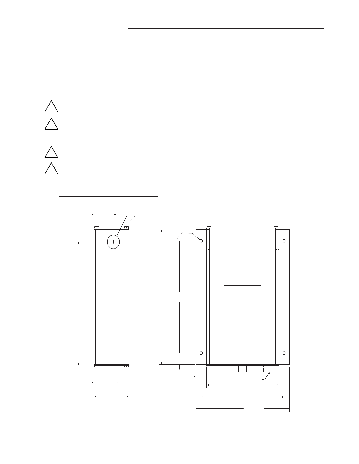
1GTM116TRANSMITTERINSTALLATION
TheGTM116transmitterisdesignedforuseinanenvironmentbetween‐20°Fto120°F(‐28.8°Cto48.8°C)where
itwillnotbeexposedtorainorsnow.Installtransmitteruprightandinafieldaccessiblelocation.Theenclosure
accepts1/2in.(12.7mm)electricalfittingsforsignalandpowerwiringatbothsidesatthetopoftheenclosure.
Locatethetransmittersothattheconnectingcablesfromallofthebleedsensorswillreachthereceptaclesonthe
bottomofthetransmitterenclosure.
Inlocationsexposedtodirectrainand/orsnow,thetransmittermustbeenclosedinaNEMA4
enclosure.
Leaveunobstructedspaceofatleast9in.(228.6mm)above,2in.(50.8mm)toeachsideand3.5
in.(88.9mm)belowthetransmittertoallowforcoverremoval,sensorconnectionsandheat
dissipation.
Locatethetransmitterinalocationthatcanbereachedbyallconnectingcablesfromthebleed
sensors.
Donotdrillintothetransmitterenclosuresincemetalshavingscoulddamagetheelectronics.
1.1 GTM116MechanicalDimensions
Figure1.GTM116MechanicalDimensions
!
!
!
!
2) IF UNIT HAS 2 PROBE CONNECTIONS THEN IT IS A TYPE "A" UNIT.
IF UNIT HAS 4 PROBE CONNECTIONS THEN IT IS A TYPE "B" UNIT.
NOTES:
1) MEASUREMENTS IN BRACKETS ARE IN MILLIMETERS.
Ø.88
[Ø22.23 mm]
6.69
[169.86 mm]
5.94
[150.81 mm]
1.38
[34.93 mm]
SEE NOTE 2
1.56
[39.67 mm]
Ø.19
[Ø4.76 mm]
2.50
[63.50 mm]
7.94
[201.55 mm]
.38
[9.53 mm]
7.19
[182.55 mm]
8.69
[220.73 mm]
.75
[19.05 mm]
5.19
[131.76 mm]
PROVIDE 3.5 INCH MINIMUM CLEARANCE AT
BOTTOM FOR CONNECTOR ACCESS.
PROVIDE 9 INCH MINIMUM CLEARANCE AT TOP
FOR COVER ACCESS (SLIDE UP TO REMOVE).
PROVIDE 2 INCH MINIMUM CLEARANCE AT BOTH
SIDES OF ENCLOSURE
1.38
[35.05 mm]
[O4.83 mm]
O.19
[182.63 mm]
[201.68 mm]
[9.65 mm]
[39.62 mm] [131.83 mm]
[150.88 mm]
[169.93 mm]
[O22.35 mm]
O.88
EBTRON • 1663 Hwy. 701 S., Loris SC 29569 • Toll Free: 800.2EBTRON (232.8766) • Fax: 843.756.1838 • Internet: EBTRON.com 5
IG_GTM116‐B_R1A
GOLD SERIES GTM116-B TRANSMITTER
a measurable difference!
EBTRON
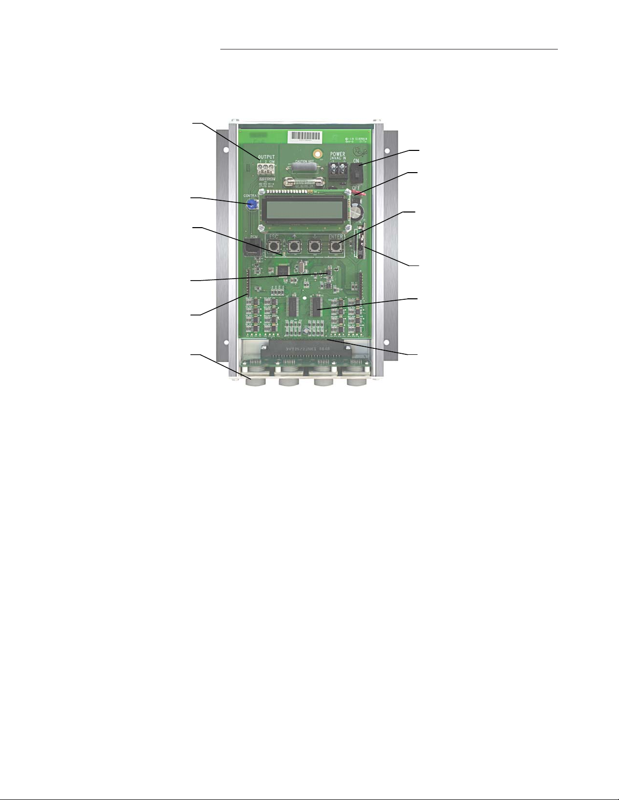
2GTM116TRANSMITTERINTERIORVIEW/FEATURES
Figure2.GTM116TransmitterInteriorView/Features
Outputsignalterminals
(Note:Theoutputfunction
isdependentonwhich
networkcardisinstalled)
LCDcontrast
TransmitterstatusLED
(Green1secondflashnormal;
2secondflashforfault)
Highaccuracy
A/Dconverter
Goldplatedinterconnects
tooptionaloutputcards
Positivelockingcable
receptacleswithgold
interconnects
Powerswitch
Switchingpowersupply
conservesenergyand
reducesheat
Pushbuttoninterface
simplifiesfieldconfiguration
(Note:devicesareplugandplayand
generallydonotrequireconfiguration.)
Expansionport
Multiplexersindependently
measuresensorvoltages
from1upto16sensingpoints
Goldplatedinterconnectsto
sensorinputreceptacles

6 EBTRON • 1663 Hwy. 701 S., Loris SC 29569 • Toll Free: 800.2EBTRON (232.8766) • Fax: 843.756.1838 • Internet: EBTRON.com
IG_GTM116‐B_R1A
GOLD SERIES GTM116-B TRANSMITTER
a measurable difference!
EBTRON
3GTM116TRANSMITTERPOWERANDSENSORCONNECTIONS
3.1 PowerTransformerSelection
Selecta24VACtransformerbasedonthemaximumpowerrequirementsindicatedonthetransmitterlabel(16
VA)orfromthetablebelow.Theoperatingsupplyvoltage(transmitterpower“ON”withallsensorprobes
connected)shouldnotbelessthan22.8VACorgreaterthan26.4VAC.
Total
Sensors
Minimum
VAReq.
Total
Sensors
Minimum
VAReq.
112 514
213 615
313 715
414 816
3.2 ConnectingPowertotheTransmitter
Connect24VACpowertothelarge,twopositionpowerinputterminallabeled“POWER”ontheupperrighthand
sideofthemaincircuitboard(Figure3).Sincetheoutputsignalsareisolatedfromthepowersupply,itisnot
necessarytoprovideanisolated(secondarynotgrounded)powersource.
MultipleGTM116transmitterswiredtoasingletransformermustbewired“in‐phase”(L1toL1,
L2toL2).
Table1.GTM116PowerTransformerSelectionGuide
Figure3.ConnectingPowertotheTransmitter
!
PowerFuse
ReplacewithUL®listed,1.5amp,fastactingonly
P.N.800‐1115(10pack)
24VACInputPower
22.8to26.4VAC
20VAmax.
L2
L1
Power
Switch
REPLACE WITH
1.5 AMP
FAST ACTING ONLY
OUTPUT
1 2 COM
POWER
24VAC IN
L2 L1
ON
OFF
EBTRON • 1663 Hwy. 701 S., Loris SC 29569 • Toll Free: 800.2EBTRON (232.8766) • Fax: 843.756.1838 • Internet: EBTRON.com 7
IG_GTM116‐B_R1A
GOLD SERIES GTM116-B TRANSMITTER
a measurable difference!
EBTRON
SQUEEZE
SQUEEZE
RECEPTACLE
LOCKING TABS
LOCKED INTO
UNDERCUT IN
RECEPTACLE
SQUEEZE
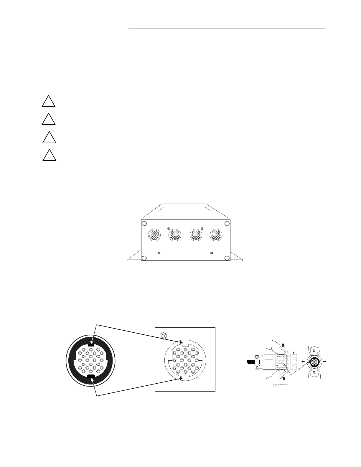
3.3 ConnectingBleedSensorstotheTransmitter
Afterinstallingthesensorsandtransmitter,connecteachofthebleedsensorcableplugstothecircular
receptacleslocatedatthebottomoftheGTM116transmitterenclosure.Bleedsensorsare“PlugandPlay”anddo
nothavetobeconnectedtoaspecificreceptacleonthetransmitterunlesstraversedataisdesired(seenote
below).TransmittersacceptonlyGP1andGB1sensors.
Providea“driploop”atthetransmitteriftherewillbethepotentialforwaterrunoffor
condensationalongthebleedsensorcable(s).
Bleedsensorcableplugsare“keyed”asshownbelow.Lineupplugwithreceptacleandpush
straightontoreceptacle.
DONOTTWIST.Squeezecableplug“ribs”towardsreceptaclewhenremoving.Forcingthecable
pluginoroutofthereceptaclewilldamagetheconnectorsandvoidwarranty.
Whentraversedataisdesired(especiallywhenusingtheEB‐LinkReader),bleedsensorsshouldbe
installedandconnectedtothetransmitterusingthemountingconventionspecifiedinthe
separateGP1/GB1sensorprobeInstallationGuide.Properinstallationsimplifiessensorlocation
decodingduringdataanalysis.
Figure4.TypeBTransmitterConnectorPanelDetail
Figure5.ConnectorDetail
TypeBTRANSMITTER
Accepts1to4bleedairflowsensors
Squeezeandthenpulltoremove
DONOTTWIST!
!
!
!
!

8 EBTRON • 1663 Hwy. 701 S., Loris SC 29569 • Toll Free: 800.2EBTRON (232.8766) • Fax: 843.756.1838 • Internet: EBTRON.com
IG_GTM116‐B_R1A
GOLD SERIES GTM116-B TRANSMITTER
a measurable difference!
EBTRON
4GTM116ANALOGOUTPUTANDNETWORKCONNECTIONS
ThissectioncontainsanalogandnetworkoutputwiringinstructionsfortheGTM116transmitterwithEthernetand
DualAnalogoutputs.
4.1 GTM116‐ANALOGOUTPUTWIRING
AnalogoutputconnectionsaremadeatthetopleftofthetransmittermaincircuitboardOUTPUTconnectoras
showninFigure6.Independentlinearanalogoutputsareprovidedforairfloworequivalentdifferentialpressureat
OUTPUTterminal1,andfortemperature(oralarm)atOUTPUTterminal2,eachwithovervoltageandovercurrent
protection.Airflowandtemperatureoutputsarefieldselectableforeither0‐5/0‐10VDCor4‐20mA.TheOUTPUT
terminal2canbeassignedasanAlarmoutputtoprovideanactivehigh,activelowortroublealarmoutput.
Outputsaregalvanicallyisolatedfromthemainpowersupplytopermitsimpleintegrationwithvirtuallyall
buildingautomationsystems.
Whenconfiguredfor4‐20mAoutput,theGTM116isa“4‐wire”device.Thehostcontrolsshallnotprovide
anyexcitationvoltagetotheoutputoftheGTM116.
Fortheanalogoutputs,shieldedcableisrecommended.Towiretheanalogoutputs,slidethecoverplateupand
offoftheenclosure.Ensurethatthepowerswitchisinthe“OFF”position.Connectsignalwiresforairflowrate(or
equivalentdifferentialpressure)andtemperature(oralarm)tothesmall,threepositionoutputterminallabeled
“OUTPUT”ontheupperlefthandsideofthemaincircuitboardasshowninFigure6.
Figure6.GTM116CombinationAnalog/Ethernet TransmitterInteriorDetail
!
ACTIVITY
TRAFFIC
LINK
D4
D3
D2
ETHERNET
10/100
ESC ENTER
CONTRAST
REPLACE WITH
1.5 AMP
FAST ACTING ONLY
OUTPUT
1 2 COM
POWER
24VAC IN
L2 L1 ON
OFF
F1
F2
VDC mA
OUT 1
OUT 2
ACTIVITY
TRAFFIC
LINK
D4
D3
D2
ETHERNET
10/100
ANALOG OUTPUT
1: Airflow
2: Temperature/Alarm
COM: Common
(RJ45 Ethernet output below)
Transmitter health/status LED
(Green 1 second flash normal;
2 second flash for trouble)
SW1 (for OUT1)
Airflow Output Signal Select
SW2 (for OUT2)
Temp./Alarm/Trouble Output
Signal Select
VDC: (0-5/0-10 VDC)
or
mA: 4-20 mA
Analog Output Fuses
F1=OUT1
F2=OUT2
UL listed 0.125 Amp
P.N. 800-1105 (Qty:10)
Power Switch
LCD Display
ACTIVITY (green) indicates
Ethernet output board health/status
(Green 1 second flash normal;
2 second flash for fault)
TRAFFIC (green) indicates
ethernet traffic
LINK (green) indicates
ethernet link status
RJ45 Ethernet Output
(For Analog Output, see
separate output above)
Combination Analog/ Ethernet
Output Board
P.N. 800-5026
ANALOG OUTPUT
1: Airflow/Differential Pressure
2: Temperature/Alarm
COM: Common
(RJ-45 Ethernet output below)
Transmitter Status LED

EBTRON • 1663 Hwy. 701 S., Loris SC 29569 • Toll Free: 800.2EBTRON (232.8766) • Fax: 843.756.1838 • Internet: EBTRON.com 9
IG_GTM116‐B_R1A
GOLD SERIES GTM116-B TRANSMITTER
a measurable difference!
EBTRON
4.2 GTM116‐ETHERNETNETWORKWIRINGCONNECTIONS
4.2.1 GTM116‐ConnectingtoanEthernetNetwork
ConnectanEthernetnetworkcabletotheRJ45networkconnectorprovidedontheGTM116Ethernet/Analog
combinationboardasshowninFigure6.
4.3 GTM116‐TransmitterSetupforEthernetNetworkOperation
Theusercanmanuallyselectnetworkprotocol(BACnet/IPorBACnetEthernet‐MODBUSTCPisalwaysenabled),
IPaddressanddeviceinstancenumber,orcansettheGTM116toautomaticallyconfigureitselfwhenusedona
network/segmentwithaDHCPserver.Bydefault,theDHCPsettingisOFF(*DHCP=OFF)formanualdevice
configuration,withBACnetIPprotocol(BACMODE=IP),astaticIPaddressof10.0.0.100,asubnetmaskof
255.255.255.0,andwithgatewaysetfor10.0.0.10.ThesevaluescanbechangedwithintheNETWORKsubmenu
asdescribedbelow.
WhenIPconfigurationiscomplete,confirmcommunicationslocallyby“pinging"theassignedGTM116IPaddress
andobserving5rapidblinksoftheACTIVITYLED(Figure6).
4.3.1 GTM116‐SelectingStaticorDynamicIPSettings
Forautomateddeviceconfigurationonanetwork/segmentwithaproperlyoperatingDHCPserver,gotothe
NETWORKMenusettings,set*DHCP=ON,set*BACMODE=forBACnet/IP(factorydefault)orBACnetEthernet
operation,andset*DI=deviceinstancenumber(factorydefault=2)asdescribedbelow.Noadditional
configurationisrequired.
FormanualdeviceconfigurationoftheGTM116,setNETWORKmenuitem*DHCP=OFF(factorydefault).When
manuallychangingIPsettings(*DHCP=OFF),thedisplaywillblinkthe3‐digitaddresssegmentthatisunderchange.
ChangetheblinkingsegmentbypressingtheUPorDOWNbuttonstoarriveatthedesiredsegmentsetting.
DepresstheENTERkeytosetthissegmentandtomovetheblinkingcursortothenext(right)segment.Repeatthis
untilthelastsegmenthasbeenselected,andthendepressENTERtostorethenewaddresssetting.
4.3.2 GTM116‐SettingEthernetTransmitterIPAddress
TheGTM116isfactorysetwithanIPaddressof10.0.0.100.Eachtransmittermustbeassignedauniqueaddresson
thenetwork/segmentitisconnectedto.TochangetheIPaddressintheNETWORKmenu,navigatetothe
*IP=10.0.0item,andsetsegmentsaspreviouslydescribed.(Seenoteaboveregarding*DHCP=OFF).
4.3.3 GTM116‐SettingSubnetMask
Tochangethisvalue,navigatetothe*MASK=255.2...NETWORKmenuitem,andsetnewsegmentvaluesas
previouslydescribed.(Seenoteaboveregarding*DHCP=OFF).
4.3.4 GTM116‐SettingGatewayIP
Tochangethisvalue,navigatetothe*GATE=10.0.0...NETWORKmenuitem,andsetnewsegmentvaluesas
previouslydescribed.(Seenoteaboveregarding*DHCP=OFF).
4.3.5 GTM116‐SettingBACnetProtocolMode
TheGTM116isfactorysetwith*BACMODE=IPforBACnetIPprotocoloperation.ThisNETWORKmenuitemcan
bechangedto*BACMODE=ETHforBACnetEthernetprotocol.
Tables3,4and5providedetailsofTCP/IP,BACnetObjectsandModbusRegisterMapsrespectively.Notethat
ModbusIPisalwaysenabledregardlessof*BACMODEsetting.
NOTE:
ForBACnetIPoperation,useport47808.ForModbusTCPoperation,useport502.ModbusIPisalways
enabledregardlessofthe*BACMODEsetting.
4.3.6 GTM116‐SettingDeviceInstanceNumber
TheGTM116isfactorysetwithaDeviceInstanceNumberof2(*DI=2).TheDeviceInstanceNumbercanbesetto
anyvaluebetween0and4194302asshowninAppendixA.TheDeviceInstanceNumbercanalsobechangedby
writingtotheDeviceObject'sObjectIdentifierPropertyoverthenetwork.

10 EBTRON • 1663 Hwy. 701 S., Loris SC 29569 • Toll Free: 800.2EBTRON (232.8766) • Fax: 843.756.1838 • Internet: EBTRON.com
IG_GTM116‐B_R1A
GOLD SERIES GTM116-B TRANSMITTER
a measurable difference!
EBTRON
4.3.7 GTM116‐ResettingCommunicationsOptionstoFactoryDefaultValues
Communicationsoptionscanberesettofactorydefaultvalues(asterisk)*valueswithintheNETWORKmenu
throughtheGTM116RESETNETmenu.
Function
Address
Type
Units Description
Range/Value
2
10001
Boolean
Trouble
Status
0:OK,
1:Trbl
4
30001-30002 float FPM
Avera
g
e
Airflow
-3,000 to 3,000
4
30003-30004 float iWG
Avera
g
e Pressure -2.5 to 2.5
4
30005-30006 float °F
Avera
g
e
Tem
p
erature
-20 to
160
4
30007
word
Numbe
r
o
f
Inserts
0to
8
4
30008
word
Alarm
Status
0: No
alarm
1: High
Alarm
2: Low
Alarm
3:
Both
4
30009
word
Connecto
r
C1
Sensors
0to
8
4
30010
word
Connecto
r
C2
Sensors
0to
8
4
30011
word
Connecto
r
C3
Sensors
0to
4
4
30012
word
Connecto
r
C4
Sensors
0to
4
4
30013-30020
float
FPM
Airflow
Flow
Traverse
-3,000 to 3
,000
30013-30014
Insert 1
Flow
↕↕
30019-30020
Insert 4
Flow
4
30021-30028
float
°F
Tem
p
erature Traverse
-20 to
160
30021-30022
Insert 1
Tem
p
↕↕
30027-30028
Insert 16
Tem
p
4
30029-30030
float
Sq.Ft. Area
0 to
100
4
300202
word
Float word
order
0: high word
first;
1: low word
first
Analog Inputs
Type, ID Name Default
Units
Device GTM116
AI, 1 Average Flow CFM
AI, 2 Average Pressure iWG
AI, 3 Average Temperature °F
AI, 4 Alarm Status 0: No alarm,
1: High Alarm,
2: Low Alarm,
3: Both
Analog Values
AV, 1 Area sq.ft.
AV, 2 Traverse Data Status 0=Disabled, 1=Flow,
2=Temp, 3=Both
AV, 3 Flow Traverse FPM
↕↕↕
AV, 18 Flow Traverse FPM
AV, 19 Temperature Traverse °F
↕↕↕
AV, 34 Temperature Traverse °F
Notes:
1. Flow and Temp traverse must be enabled through AV2.
2. User Executed Services Supported:
Subscribe COV, Read Property, Write Property,
Device Communication Control, Who-Is.
Table3. GTx116‐BBACnetObjectsList
BACnetMS/TP
NOTE:ForGTM116BACnetIPoperation,useport47808.
Table2. GTM116TCP/IPExample
Table4. GTx116‐BModbusRegisterMap
NOTE: For GTM116 Modbus operation, use port 502. Modbus IP is always enabled regardless
o
f *BA
C
M
O
DE
set
t
in
g
.
GTM Data
Value
525
0.0553
89
Pressure
Temperature
Flow
TCP/IP
http://10.0.0.100
(or your custom IP address)
Parameter

EBTRON • 1663 Hwy. 701 S., Loris SC 29569 • Toll Free: 800.2EBTRON (232.8766) • Fax: 843.756.1838 • Internet: EBTRON.com 11
IG_GTM116‐B_R1A
GOLD SERIES GTM116-B TRANSMITTER
a measurable difference!
EBTRON
5GTM116TRANSMITTERSTART‐UP,INITIALIZATIONANDSETUPMENUS
Toensureasuccessfulstart‐up,verifythatthebleedsensorsandtransmitterareinstalledinaccordancewith
EBTRONguidelines.
Checkthephysicalinstallation,powerconnectionsandmodelspecificsignalwiringpriortoturningthe
powerswitchtothe“ON”position.
Movethepowerswitchtothe“ON”position.Thetransmitterexecutesacompleteself‐checkeachtimethepower
isturnedonthattakes10secondstocomplete.
5.1 ChangingtheSystemofUnits‐IPorSIUnits
TheGTM116transmitterisprovidedwiththesystemofunitssettoIP.TochangetoSIunits,simultaneouslypress
andreleasethe“ENT”and“ESC”buttonsduringnormaloperation.“IP/SIUNITS”willbeindicatedontheLCD
display.RefertoAppendixASYSTEMOFUNITSMENUfordetailsontheSystemofUnitsmenu.NotethatSetup
MenuitemsareshowninIPSystemOfUnits.WhenSISystemofUnitsisselected,theunitsofmeasure
abbreviationsusedinthemenusisshowninTable5.
“IP”SystemofUnitsDescription“SI”SystemofUnits Description
FPMFeetperminuteMPS Meterspersecond
CFMCubicfeetperminuteLPS Literspersecond
SQFSquarefeetSQM Squaremeters
FFahrenheit CCelsius
iWGInchofWaterGauge PA Pascal
5.2 GTM116TransmitterCalibration
TheGTM116useshighqualityindustrialgradecomponentsandisdesignedforyearsoftrouble‐freeoperation.
Periodicrecalibrationofthetransmitterisneitherrequiredorrecommended.Transmitterfieldcalibrationverifiers
areavailableforpurchasefromEBTRONforinstallationsrequiringperiodicvalidationofinstrumentation.Contact
EBTRONformoreinformation.
5.3 GTM116LCDDisplayNotifications
Followingabriefinitializationatpowerup,theLCDdisplayautomaticallydisplaysairflowandtemperaturewith
unitsofmeasurementinalluppercase(caps)characters.Thedisplayprovidesadditionalinformationonsystem
statusandalarmconditions.RefertotheALARMFEATURESsectionofthismanualforadditionaldetailonAlarm
andTroubleErrorcodeindications.
Table5.Standard“IP”and“SI”MenuUnitsAbbreviations
!

12 EBTRON • 1663 Hwy. 701 S., Loris SC 29569 • Toll Free: 800.2EBTRON (232.8766) • Fax: 843.756.1838 • Internet: EBTRON.com
IG_GTM116‐B_R1A
GOLD SERIES GTM116-B TRANSMITTER
a measurable difference!
EBTRON
5.4 FactoryDefaultMenuSettingsforGB1BleedSensors
TheGTM116transmitteris“plugandplay”anddoesnotrequiresetupunlessanetworkoptionisselectedthat
requiresconfiguration.Table6showsthefactorydefaultsettingsforallcompatiblesensorprobes.
TochangetheFactoryDefaultSettings,see:CHANGINGFACTORYDEFAULTSETUPMENUSETTINGS.
Display Description I-P S.I.
AIRFLOW= Airflow measurement method, Actual or Standard. ACT ACT
*LCDU/M= Airflow units of measure AFPM MPS
*AREA= Free area where station is located (required for volumetric measurement) 0.00 sq.ft. 0.000 sq.meters
*AO1 SGNL= Output 1 signal type voltage or mA (airflow) mA mA
*AO1 UM= Output 1 units of measure AFPM AMPS
*AO1 MS= Output 1 signal minimum scale 0 FPM 0 MPS
*AO1 FS= Output 1 signal full scale 3,000 FPM 25 MPS
*MEAS= Display and output measurement type (airflow or pressure) AIRFLOW AIRFLOW
*FLOW ADJ= Output 1 Offset-Gain On/Off Off Off
*GAIN= Output 1 Gain factor 1.000 1.000
*OFF= Output 1 Offset factor 0.000 0.000
*AO2 SGNL= Output 2 signal voltage or mA (temperature or alarm) mA (see alarms) mA (see alarms)
*AO2 MS= Output 2 signal minimum scale -20º F -30º C
*AO2 FS= Output 2 signal full scale 160º F 70º C
*LCD INTG= Number of flow calculations to be averaged for LCD display. 100 100
*AO1 INTG= Number of flow calculations to be averaged for AO1 output. 30 30
*EB-LK INT= Number of flow calculations to be averaged for EB-Link readings. 300 300
*ALT= Altitude for flow correction relative to mean sea level (0 ft). 0 ft 0 m
*AO2 ASGN = *AO2 ASGN = TEMP Output 2 Assigned Type is Temperature TEMP TEMP
*SETPNT= Alarm setpoint value. For AO2 ASGN=ALARM , operates in conjunction
with TOL=value.
0 0
*TOL= Alarm range tolerance value. For AO2 ASGN=ALARM , this setting
establishes the alarm range relative to the SETPNT= value.
0 0
*NO FAULT= Sets the AO2 normal (not alarm) output state relative to the full scale
analog output selected. HI provides maximum full scale under normal
conditions and minimum scale during alarm. LO provides minimum full
scale under normal conditions and maximum scale during alarm.
HI HI
*DELAY= Time that the alarm condition must exist before alarm output is activated. 2 minutes 2 minutes
*RESET = Set to AUTO to have alarm self-clear when alarm condition no longer
exists. Set to MANUAL to require manual reset of alarm.
AUTO AUTO
Table6. FactoryDefaultMenuSettings

EBTRON • 1663 Hwy. 701 S., Loris SC 29569 • Toll Free: 800.2EBTRON (232.8766) • Fax: 843.756.1838 • Internet: EBTRON.com 13
IG_GTM116‐B_R1A
GOLD SERIES GTM116-B TRANSMITTER
a measurable difference!
EBTRON
5.5 GTM116ChangingFactoryDefaultSetupMenuSettings
5.5.1 SetupMenuOptions
TheGTM116Transmitterissetupandtestedatthefactorytobefullyoperationalwhensensorsareconnectedand
powerisapplied(setthepowerswitchtothe“ON”position).Factorysettingscaneasilybechangedusingthe
SETUPMENUbysimultaneouslypressingandreleasingthe“UP”and“DOWN”buttonswhilethetransmitterisin
itsnormaloperatingmode.AppendixAdetailstheSETUPmenus.NavigatethroughtheSETUPmenustomake
changestothetransmitterconfiguration.Thesettingstakeeffectimmediately.Thefollowingarecommonfield
modificationstothefactorydefaultsettings.
5.5.2 SelectingAirfloworPressureMeasurementType
ThetransmitterissetfromthefactorytoprovideairflowmeasurementwithbothLCDandanalogoutputunitsin
FPM.Ifdesired,theoutputcanbesettoprovidepressuremeasurementwithbothLCDandanalogoutputunitsin
iWGbyengagingtheMEAS=menuitem,andselecting'PRESS'.
5.5.3 SelectingActualandStandardOutputMeasurementType
Thetransmitterissetfromthefactorytoprovideactualairflowmeasurementunits(displayedas“ACFM”and
“AFPM”).Inthismode,airflowmeasurementsarecalculatedforactualairflowconditions.Ifusingactualairflow,
correctionsforaltitudeareenteredthroughtheALT=settingintheSetupmenu.Ifdesired,theoutputcanbeset
toprovidestandardairflowmeasurementunits(displayedas“SCFM”and“SFPM)whichprovidesmeasurements
thatarecorrectedtostandardconditions.
5.5.4 OutputScaling
EBTRON’sGoldSeriessensorsareindividuallycalibratedbetween0andthefactorydefaultfullscaletostandards
traceabletotheNationalInstituteofStandardsandTechnology(NIST).Sensorsareindependentandproduce
“percentofreading”accuracy.Changingthefullscalevaluedoesnotchangetheaccuracyofthedevice.Factory
defaultanalogoutputscalingcanbechangedwithintheSETUPmenus.
5.5.5 LockingtheConfigurationSettings
TheGTM116transmitterconfigurationsettingscanbelockedatoneofthreesecuritylevelswithintheSECURITY
submenuusingtheLOCKSEC=item.
WhenLOWsecuritylevelisselected(LOCKSEC=LOW)thelast4digitsoftheboardserialnumberareautomatically
assignedasthelockcode.Toseetheboardserialnumber,navigatetoDIAGNOSTICSmenuinSERIALNUMBERS
item.
WhentheMEDsecuritylevelisselected(LOCKSEC=MED)theuserentersandconfirmsasecuritycode.Inthe
eventthatthiscodeislost/misplaced,EBTRONcanprovideakeythatisuniquetothetransmittertounlockit.
ContactEBTRONcustomerserviceforthiscode.
WhentheHIGHsecuritylevelisselected(LOCKSEC=HIGH)theuserentersandconfirmsasecuritycode.Inthe
eventthatthiscodeislost/misplaced,thetransmittermustbereturnedtothefactoryinordertounlockit.
WhenLOCKSEC=HIGHisselected,theuserdefinedsettingcanonlybechangedafterenteringtheuser
definedcode.STORETHELOCKCODEINASAFELOCATION!Forsecurityreasons,theHIGHlevellockcode
canonlyberesetbyreturningthetransmittertothefactory.
!

14 EBTRON • 1663 Hwy. 701 S., Loris SC 29569 • Toll Free: 800.2EBTRON (232.8766) • Fax: 843.756.1838 • Internet: EBTRON.com
IG_GTM116‐B_R1A
GOLD SERIES GTM116-B TRANSMITTER
a measurable difference!
EBTRON
5.6 GTM116‐AlarmFeatures
AnalogoutputAO2(OUT2)canbeassignedtofunctionasanalarmoutput.TheAO2alarmoutputcanbe
assignedintheSETUPmenutooperateasanalarmforaverageairfloworpressuredependingonMEAS=
setting(A02ASGN=ALRM)orasatroublealarm(AO2ASGN=TRBL)formonitoringthestatusofthetransmitterand
sensors.TheAO2ASGN=settingislocatedintheANALOGOUTsubmenuoftheSETUPmenu.ThetransmitterLCD
displaywillindicatetheAlarmstatusfor2seconds,andwillcyclethroughanyotheralarmsifmultiplealarm
eventsareactivefor2secondseach,andthendisplaythecurrentactualflowfor2seconds.Detailedsetupofthe
AlarmfeaturesisshownintheSetupmenu.
5.6.1 AverageAlarm(AO2ASGN=ALRM)
AO2outputisassignedasanaverageairflowalarmoutput.Usefulforapplicationswherealowflowalarm,ahigh
flowalarmforoperationoutsideofadefinedrange(setpointandtolerance)isrequired.
5.6.2 TroubleAlarm(AO2ASGN=TRBL)
AO2outputisassignedasatransmittertroublealarmindicatingafaultwithinthetransmitterorasensorofthe
airflowmeasurementsystem.ThetransmitterLCDwillindicateatroublecodeandabriefdescriptionofthe
trouble.ContactEBTRONcustomerserviceforadditionalinformationorassistancewithtroublecodes.
5.6.3 NoFault(NOFAULT=HI)
WhenAO2outputisassignedasanalarm,thissettingconfiguresthenormaloutputconditiontobeHIorLO
relativetothefullscaleanalogoutputlevelselectedwhennofaultconditionexists.
5.6.4 AlarmIndications
Table7detailsthealarmtypes,LCDindicationsandAO2alarmoutputindications.Usercanselecteitherorbothof
thetwoAverageAlarmsortheTroubleAlarm:
5.6.5 LowAlarm‐“LOALRM=ON”
TheLowAlarmisactivatedwhentheaverageairflowfallsbelowaselectedsetpoint(SETPNT=)‐tolerance(TOL=)
value.Onceactive,thealarmcanbeclearedwhentheaverageairflowrisesabovethesetpoint‐tolerancevalue.
5.6.6 HighAlarm‐“HIALRM=ON”
TheHighAlarmisactivatedwhentheaverageairflowrisesaboveaselectedsetpoint(SETPNT=)+tolerance
(TOL=)value.Onceactive,thealarmcanbeclearedwhentheaverageairflowfallsbelowthesetpoint+tolerance
value.
5.6.7 TroubleAlarm‐“AO2ASGN=TRBL”
TheTroublealarmprovidestroublecodesusefulforisolatingsetupissuesorproblemswithinthetransmitteror
sensors.ThetransmitterLCDwillindicateTROUBLE!regardlessofwhetherAO2isassignedtoTRBL.TheDiagnostic
submenucanbeengagedfortheerrorcodeandabriefdescriptionofthetrouble.ContactEBTRONcustomer
serviceforinformationontroubleshootingusingtheTroubleerrorcodes.
Table7.GTM116AlarmTypesandNotifications
ALARM OUTPUT
ASSIGNMENT TYPE
LOCAL LCD DISPLAY OF ALARM
TYPE AND NOTIFICATION
ANALOG OUTPUT 2
ALARM INDICATION
NETWORK
ALARM INDICATION
**LOW ALARM**
(Average Alarm)
Display alternates between **LOW
ALARM** (then any other alarms) and
actual reading for 2 seconds each.
**HIGH ALARM**
(Average Alarm)
Display alternates between **HIGH
ALARM** (then any other alarms) and
actual reading for 2 seconds each.
TROUBLE !
(Trouble Alarm)
Display indicates TROUBLE !
(Refer to DIAGNOSTIC menu to obtain a
brief description of the error and any
other alarms).
On alarm or trouble, OUT2 is
active high (or active low)
relative to the full scale
maximum (or minimum)
analog value as determined
by the SETUP Menu “NO
FAULT=” selection. Individual
sensor velocities can be
viewed using the Diagnostics
submenu.
Alarm Status is available at
BACnet Objects and
Modbus Registers. Refer to
BACnet Objects List and
Modbus Register Map for
additional detail.

EBTRON • 1663 Hwy. 701 S., Loris SC 29569 • Toll Free: 800.2EBTRON (232.8766) • Fax: 843.756.1838 • Internet: EBTRON.com 15
IG_GTM116‐B_R1A
GOLD SERIES GTM116-B TRANSMITTER
a measurable difference!
EBTRON
5.7 GTM116‐AnalogOutputTypeSelectionandSetup
TheanalogoutputsignaltypeatAO1(OUT1,airflow)andAO2(OUT2,temperature/alarm)canbesetformAor
VDCoutputbysettingswitchesSW1/SW2(Figure6)andbyselectingthe4‐20mA,0‐5VDCor0‐10VDCrangesin
theANALOGOUTsubmenuoptions*AO1RNGE=/*AO2RNGE=settings.Thetransmitterisshippedfromthe
factorywithSW1/SW2andSetupmenuoptions*AO1RNGE=and*AO2RNGE=setfor4‐20mA.
5.7.1 GTM116‐ConvertingAnalogOutputSignalValuestoAirflowandTemperature
Table8listsspecificconversionequationsforanalogvoltageorcurrentoutputoptions.
5.7.2 GTM116‐AO1/AO2OUTPUTTEST‐SendingaTestOutputSignaltotheHostControl
System
Atestoutputsignalbetween0and100%ofthefullscaleoutput(4‐20mAor0‐5VDC/0‐10VDC)canbeprovided
bytheGTM116transmittertoverifyproperconversionoftheoutputsignalsfromthetransmitteratthehost
controlsystem.Tosetafixedoutputsignalforairflowandtemperature,navigatetotheOUTPUTTESTsubmenuin
theTOOLSmenu.OUT1andOUT2testsareindependentlyaccessed,andtheoutputwillmaintainthe%selected
untilthe“ESC”buttonispressedandnormaloperationresumes.
Table8.GTM116ConvertingAnalogOutputValuestoAirflow/Temperature
TO CONVERT TO
Airflow (FPM, MPS) or
Differential Pressure
(iWG, Pa)
Output Voltage/10 * (FS1 - MS1) + MS1 Output Voltage/5 * (FS1 - MS1) + MS1 (Output Current-4)/16 * (FS1 - MS1) + MS1
TO CONVERT TO
Temp (°F,°C) Output Voltage/10 * (FS2 - MS2) + MS2 Output Voltage/5 * (FS2 - MS2) + MS2 (Output Current - 4)/16 * (FS2 - MS2) + MS2
NOTES:
FS1 is AO1 full scale analog output value from ANALOG OUT MENU.
FS2 is AO2 full scale analog output value from ANALOG OUT MENU.
MS1 is AO1 minimum scale analog output value from ANALOG OUT MENU.
MS2 is AO2 minimum scale analog output value from ANALOG OUT MENU.
Airflow (FPM) from Differential Pressure (iWG)
ANALOG OUTPUT SCALING AND TYPE
0-10 VDC 0-5 VDC 4-20 mA
When OUTPUT 1 is Configured as Airflow (FPM, MPS) or Pressure (iWG, PA):
ANALOG OUTPUT SCALING AND TYPE
0-10 VDC 0-5 VDC 4-20 mA
When OUTPUT 2 is Configured as Temperature (°F,°C):
TO CONVERT TO
Differential Pressure (iWG) = Airflow (FPM) ^2/(2232^2)
Airflow (FPM) = 2232 * (Differential Pressure (iWG) ^0.5)
Differential Pressure (iWG) from Airflow (FPM)

16 EBTRON • 1663 Hwy. 701 S., Loris SC 29569 • Toll Free: 800.2EBTRON (232.8766) • Fax: 843.756.1838 • Internet: EBTRON.com
IG_GTM116‐B_R1A
GOLD SERIES GTM116-B TRANSMITTER
a measurable difference!
EBTRON
5.8 ViewingSensorData
5.8.1 ViewingSensorDataontheLocalLCDDisplay
AirflowandtemperatureofindividualsensorscanbedisplayedonthelocalLCDdisplaybyenteringthe
DiagnosticMenu.Simultaneouslydepresstheup↑anddown↓arrowstoentertheGTM116SETUPmenu,and
thennavigatetotheDiagnosticsubmenu.
5.8.2 ViewingSensorDataviaBACnet,ModbusnetworksorviaEB‐LinkReader
AirflowandtemperatureofindividualsensorscanbereadacrossBACnetorModbusnetworks,ordownloaded
directlytoanEB‐LinkReaderiftheinfra‐redEB‐Linkoptionhasbeeninstalled.RefertothefollowingSensor
Addressingparagraphforthesuggestedprobeinstallationconfiguration.Tables3and4provideBACnetobjects
andregisteraddressinginformationforindividualsensordata.
5.8.3 SensorAddressing
ThebleedsensorsareaddressedinorderfromlefttorightfromC1toC4basedontheconnectoronthe
transmitter.TheleftmostconnectorisC1.
6SETUPMENUS
AppendixAdetailsthevarioussetupmenusandsubmenus.
7WIRINGDIAGRAM
AppendixBisthewiringdiagramfortheGTM116transmitter.

EBTRON • 1663 Hwy. 701 S., Loris SC 29569 • Toll Free: 800.2EBTRON (232.8766) • Fax: 843.756.1838 • Internet: EBTRON.com 17
IG_GTM116‐B_R1A
GOLD SERIES GTM116-B TRANSMITTER
a measurable difference!
EBTRON
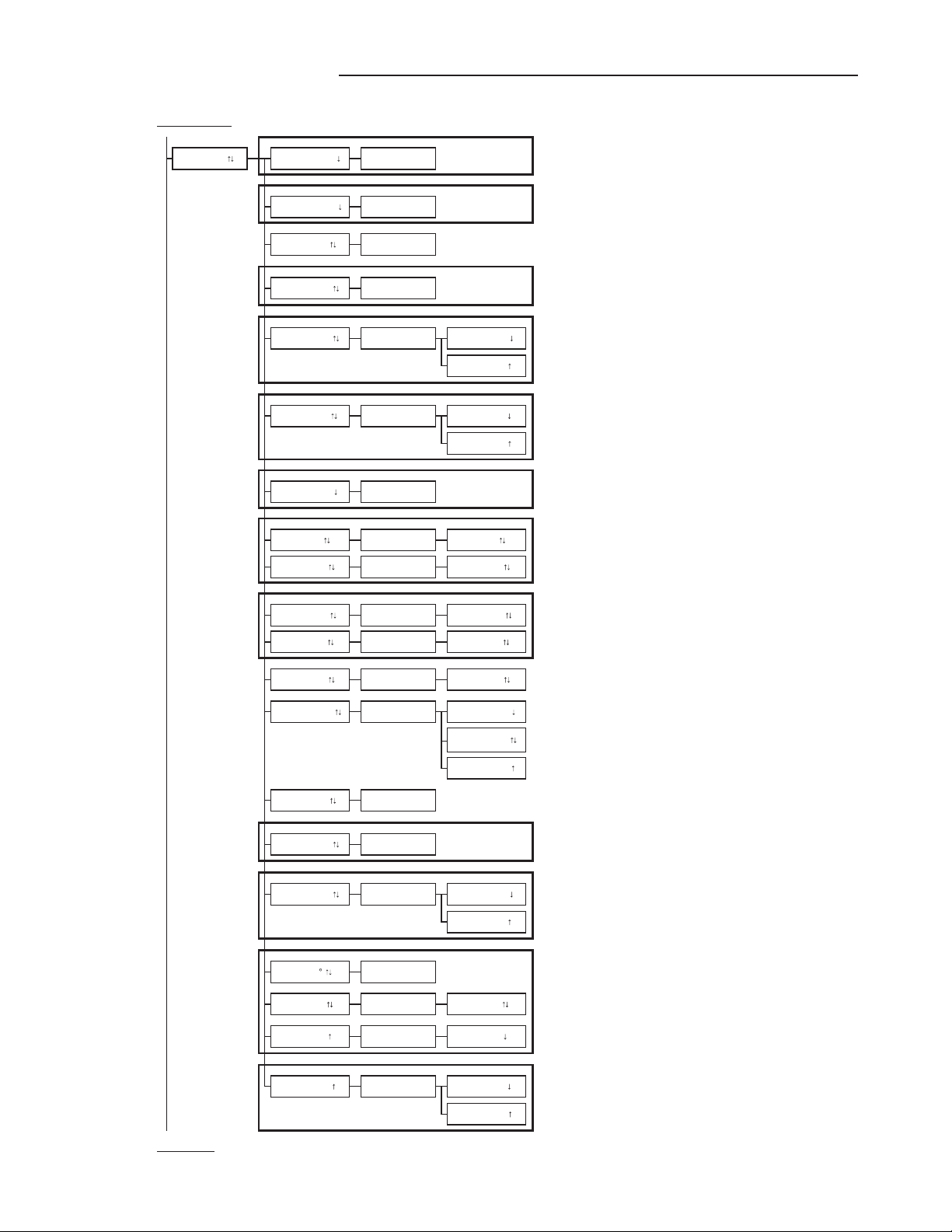
APPENDIXA‐
ADVANTAGE3‐BLEEDSENSORSETUPMENUS
SYSTEM OF UNITS MENU
Simultaneously depress/release ENTER + ESC keys during normal operation to select
* Factory Default/Current Setting
Enter (move ) Enter (move ) Enter (action, move )
Esc (normal oper.) Esc (move )Esc (move )
ACTION
SETUP MENU
Simultaneously depress/release + keys during normal operation to select
* Factory Default/Current Setting
Enter (move ) Enter (move ) Enter (move ) Enter (move ) Enter (action, move )
Esc (normal oper.) Esc (move or prev setting) Esc (move or prev setting) Esc (move )Esc (move )
ACTION
if MEAS=AIRFLOW
Only when AIRFLOW=ACT
if MEAS=AIRFLOW
if MEAS=AIRFLOW
if MEAS=PRESS
TO PART 5 'A' TO PART 2
Set the altitude above sea level for flow correction: 0 to 18,000 ft.
Set what is displayed on LCD.
O
*LCD INTG=100 SET LCD INTG? Integration samples for LCD
*LCD TRBL=ON SET LCD TRBL? LCD TRBL=OFF
Custom LCD Flow Text: Blinking prompt at position of the selected character. Character is
selected using the up and down arrows and then ENTER to accept and move cursor forward
(right); ESC moves the cursor back (left). Use space characters
for blank or unwanted text.
*EXT CABLE=0 SET EXT CABLE? EXT CABLE=0
LCD TRBL=ON
Set measurement mode to AIRFLOW
MEAS=PRESS
*LCD DSPL=BOTH
SETUP Instruction text:
"USE AND ENT"
then:
NAME= _
GENERAL
SET ON FAIL? ON FAIL=LO
*LCD UM=iWG
AIRFLOW=STD
LCD UM FIXED
*NAME={unit serial#} SET NAME ?
DISPLAY
ALT=0
*ON FAIL=LO
Enter length of extension cable
SET LCD DSPL?
IP/SI=IP SYS
*LCD UM=AFPM
SET MEAS?
IP/SI=SI SYS
*ALT=0
SET IP/SI ?
AREA=0.00
*IP/SI=IP SYS
*AIRFLOW=ACT SET AIRFLOW? Set the airflow measurement to ACTUAL units (AFPM/ACFM)AIRFLOW=ACT
*MEAS=AIRFLOW MEAS=AIRFLOW
SET AREA? Enter area
Set measurement mode to PRESSURE
Set the airflow measurement to Standard units (SFPM/SCFM)
SET ALT?
*AREA=0.00
Sets transmitter analog output state in the event of a major fault (all sensor failure) expressed as
HI for full scale analog output or LO as minimum scale analog output.
if MEAS=PRESS:
LCD DSPL=PRESS
Set LCD units of measure to CFM or FPM. (Note: A if ACT or S if STD measurement prefix set
by AIRFLOW= setting above)
LCD UM=ACFM
The text "LCD UM FIXED" flashes to indicate that this setting is fixed and cannot be modified.
ON FAIL=HI
LCD DSPL=OFF
SET LCD UM? LCD UM=AFPM
if MEAS=AIRFLOW:
LCD DSPL=FLOW
LCD DSPL=BOTH
LCD INTG=100
O
Set whether or not TROUBLE will display on LCD during a trouble condition.
Set system of units to I-P (FPM, CFM, sq.ft., °F)
or
Set system of units to S.I. (MPS, LPS, sq.M., °C).
NOTE: Changing IP/SI SYS resets alarm settings and scaling values.
LCD DSPL=TEMP
18 EBTRON • 1663 Hwy. 701 S., Loris SC 29569 • Toll Free: 800.2EBTRON (232.8766) • Fax: 843.756.1838 • Internet: EBTRON.com
IG_GTM116‐B_R1A
GOLD SERIES GTM116-B TRANSMITTER
a measurable difference!
EBTRON
FROM PART 1
Analog cards only if MEAS=AIRFLOW
if MEAS=PRESS
if AO1 SGNL=mA
if AO1 SGNL=VDC
if MEAS=AIRFLOW
if MEAS=PRESS
if MEAS=AIRFLOW
if MEAS=PRESS
if AO2 SGNL=mA
if AO2 SGNL=VDC
if AO2 CFG=TEMP
if AO2 CFG=ALRM or TRBL
TO PART 3
Set analog output range (VDC) for AO2.
Set AO1 minimum scale
O
O
*AO1 RNGE=0-10
*AO2 RNGE=4-20
SET SW1 ON PCB
*AO1 RNGE=4-20 AO1 RNGE=FIXED
*AO1 MS=0
AO1 UM=ACFM
AO1 UM=AFPM
AO2 ASGN=TRBL
*A01 SGNL=mA
The text "AO1 ASGN FIXED" flashes to indicate this setting is fixed and cannot be modified.
Set AO1 units to FPM or CFM (Note: A if ACT or S if STD measurement prefix set by
AIRFLOW= setting above)
Display initially shows the current SW1 PCB switch setting (VDC or mA) for AO1. Pressing
enter displays "SET SW1 ON PCB" prompt to confirm SW1 PCB setting.
Integration samples. Also same as network integration.
AO1 MS=0
Display initially shows the current SW2 PCB switch setting (VDC or mA) for AO2. Pressing
enter displays "SET SW2 ON PCB" prompt to confirm SW2 PCB setting.
Set AO2 full scale
Set AO1 minimum scale
Set AO1 full scale
The text "AO1 ASGN FIXED" flashes to indicate this setting is fixed and cannot be modified.
*AO1 ASGN=iWG AO1 UM FIXED The text "AO1 UM FIXED" flashes to indicate that this setting is fixed and cannot be modified.
ANALOG OUT *AO1 ASGN=FLOW
SET AO1 RNGE?
*AO1 ASGN=PRESS AO1 ASGN FIXED
AO2 RNGE=0-5
Set analog output range (VDC) for AO1.
*AO1 UM=AFPM SET AO1 UM?
*AO2 ASGN=TEMP SET AO2 ASGN? AO2 ASGN=TEMP
SET AO1 MS?
*AO1 INTG=30 SET AO1 INTG? AO1 INTG=30
Set AO2 minimum scale
AO2 output is assigned as temperature output.
AO2 RNGE=0-10
*NO FAULT = HI SET NO FAULT? NO FAULT = HI
The text "AO2 RNGE=FIXED" flashes to indicate this setting is fixed and cannot be modified.
SET AO2 MS? AO2 MS=-20
*AO2 UM= F AO2 UM FIXED The text "AO2 UM FIXED" flashes to indicate this setting is fixed and cannot be modified.
AO2 ASGN=ALRM
*A02 SGNL=mA SET SW2 ON PCB
*AO2 RNGE=0-10 SET AO2 RNGE?
AO2 RNGE=FIXED
SET AO2 FS?
NO FAULT = LO
*AO2 MS=-20
AO2 FS=160*AO2 FS=160
*AO1 MS= -0.25 SET AO1 MS? AO1 MS= -0.25
*AO1 FS=3000 SET AO1 FS? AO1 FS=3000 Set AO1 full scale
The text "AO1 RNGE=FIXED" flashes to indicate this setting is fixed and cannot be modified.
AO1 ASGN FIXED
AO1 RNGE=0-10
AO1 RNGE=0-5
*AO1 FS=0.25 SET AO1 FS? AO1 FS=0.25
AO2 output is assigned as an airflow alarm output.
Refer to ALARM settings (part 4).
AO2 output is assigned as a transmitter trouble alarm indicating that a sensor or transmitter fault
has occurred.
Sets AO2 alarm/trouble output state when no fault condition is present, expressed as HI (full
scale analog output) or LO (minimum scale analog output).

EBTRON • 1663 Hwy. 701 S., Loris SC 29569 • Toll Free: 800.2EBTRON (232.8766) • Fax: 843.756.1838 • Internet: EBTRON.com 19
IG_GTM116‐B_R1A
GOLD SERIES GTM116-B TRANSMITTER
a measurable difference!
EBTRON
FROM PART 2
GTC only GTC configuration
Option for MODBUS only
Option for BACNET only
GTM only GTM configuration
TO PART 4
Set DHCP to ON or OFF.
SET MASK? 255.255.255.000
Enter IP address, use (up/down arrow) buttons to select value and press ENT to move to right
and ESC to move to left.
Set network device instance number.
NETBAUD=19200
NETBAUD=9600
Enter network address
Enter subnet mask, use (up/down arrow) buttons to select value and press ENT to move to right
and ESC to move to left.
Set network device instance number.
Set network protocol type
Enter gateway IP address, use (up/down arrow) buttons to select value and press ENT to move
to right and ESC to move to left.
Set BACnet IP or Ethernet protocol
NETWORK
*IP=10.0.0.1
EB-LINK
PARITY=ODD
Set MODBUS parity type.
Set network baud rate.
NETWORK
*NETOUT=BACNET
O
O
SET NETBAUD?*NETBAUD=76800
SET DHCP?
SET NETADDRESS?
*NETDI=2
NETOUT=BACNET
NETOUT=MODBUS
*NETADDRESS= 2 NETADDRESS=2
SET NETOUT?
NETBAUD=76800
*PARITY=EVEN SET PARITY?
NETBAUD=38400
PARITY=NONE1
PARITY=NONE2
PARITY=EVEN
SET BACNET?
*MASK=255.255.
NETDI=2
*DHCP=OFF DHCP=OFF
BACNET=IP
SET NETDI?
010.000.000.001
*NETDI=2 SET NETDI? NETDI=2
SET GATE?*GATE=10.0.0..
DHCP=ON
SET IP?
010.000.000.010
BACNET=ETH
*BACNET=IP
*EB-LK INTG=300 SET EB-LK INTG? EB-LK INTG=300 EB-Link integration samples

20 EBTRON • 1663 Hwy. 701 S., Loris SC 29569 • Toll Free: 800.2EBTRON (232.8766) • Fax: 843.756.1838 • Internet: EBTRON.com
IG_GTM116‐B_R1A
GOLD SERIES GTM116-B TRANSMITTER
a measurable difference!
EBTRON
FROM PART 3
if MEAS=AIRFLOW
if MEAS=PRESS
TO PART 5 'B'
RESET=MANUAL
*HI ALRM=OFF SET HI ALRM?
O
O
LO ALRM=OFF Enable/disable LO alarm.*LO ALRM=OFF
*SETPNT=0 SET SETPNT? SETPNT=0 Enter setpoint for alarm
ALARM
HI ALRM=ON
*ALRM UM=AFPM SET ALRM UM? ALRM UM=AFPM
*TOL=0 SET TOL? TOL=0 Enter tolerance as value above or below alarm setpoint. Units based on ALARM UM.
*DELAY=2 MIN SET DELAY? DELAY=2 MIN Enter alarm delay
*RESET=AUTO SET RESET? RESET=AUTO Set alarm RESET. AUTO will clear once the alarm is not active. MANUAL requires user to clear
alarm by depressing the ESC key, or for RS485 (GTC/GTM models) output, write 0 to
corresponding alarm BACnet object or Modbus register. Alarm will only clear when alarm is not
active.
*ALRM UM=iWG ALRM UM FIXED The text "ALRM UM FIXED" flashes to indicate this setting is fixed and cannot be modified.
ALRM UM=ACFM
Set alarm units of measure to FPM or CFM (Note: A if ACT or S if STD measurement prefix set
by AIRFLOW= setting above)
LO ALRM=ON
SET LO ALRM?
Enable/disable HI alarm.HI ALRM=OFF
This manual suits for next models
1
Table of contents
Other Ebtron Transmitter manuals


Popular Transmitter manuals by other brands

LYNXTechnik
LYNXTechnik Yellobrik OTX 1742 quick reference

Key Digital
Key Digital KD-X3x1WUTx operating instructions

Endress+Hauser
Endress+Hauser Liquiline M CM42 Functional safety manual

HYDACELECTRONIC
HYDACELECTRONIC HPT 500 Series operating manual

ATO
ATO Aerielle AudioBUG user manual

Hitech
Hitech Nivelco Nivocap C-200 Installation and programming manual


