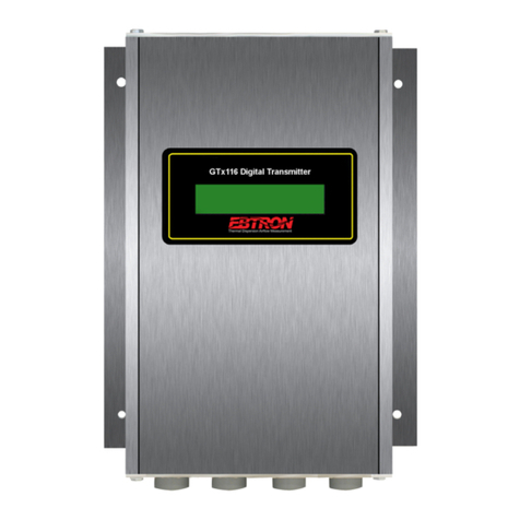
Ebtron GTx116 User manual

a measurable difference!
®
Gold Series Thermal Dispersion Airflow Measurement Technology
Model GTx116
Technical Manual
Advantage III
Gold Series by Ebtron
Installation, Operation and Maintenance Technical Manual
GTx116
“Plug & Play” Transmitters
Combination RS-485 and Dual Analog output model: GTC116
Combination Ethernet and Dual Analog output model: GTM116
LonWorks®output model: GTL116
Data Logger output model: GTD116
Document Name: TM_GTx116_R9A1
EBTRON, Inc. 1663 Hwy. 701 S., Loris SC 29569 • Toll Free: 800.2EBTRON (232.8766) • Fax: 843.756.1838 • Internet: EBTRON.com
TM_GTx116_R9A1
LISTED
European Union
Shipments
Part Number: 930-0000
Models GTC116 and GTM116
BACnet is a registered trademark of ASHRAE. ASHRAE does not endorse, approve or test
products for compliance with ASHRAE standards. Compliance of listed products to the
requirements of ASHRAE Standard 135 is the responsibility of BACnet International (BI).
BTL is a registered trademark of BI.
Models GTC116 and GTE116

a measurable difference!
®
Copyright © 2015, EBTRON ®, Inc.
All brand names, trademarks and registered trademarks are the property of their respective owners. Information contained within this document is subject to
change without notice. Visit EBTRON.com to view and/or download the most recent versions of this and other documents.
All rights reserved.
LIST OF EFFECTIVE AND CHANGED PAGES
Insert latest changed pages (in bold text); remove and dispose of superseded pages.
Total number of pages in this manual is 44.
Page No Revision * . . . . . . .Description of Change . . . . . . . . . . . . . . . . . . . . . . . . . . . . . . . . . . . . . . . .Date
1, 2 . . . . . . . . . . . .R9A . . . . . . . . . . . . . . . .Updated revision to R9A . . . . . . . . . . . . . . . . . . . . . . . . . . . . . . . . . . . . . . . . . . . . . . . . . . . . . . . . . . . . . . . . . . . .05/13/2016
3-44 . . . . . . . . . . .R9A . . . . . . . . . . . . . . . .Minor corrections to reflect Advantage 3 Setup Menus changes for consistency among products . . . . . . . .05/13/2016
1-44 . . . . . . . . . . .R8A . . . . . . . . . . . . . . . .All pages revised/updated to reflect Advantage 3 updates . . . . . . . . . . . . . . . . . . . . . . . . . . . . . . . . . . . . . . . .01/21/2015
2EBTRON, Inc. 1663 Hwy. 701 S., Loris SC 29569 • Toll Free: 800.2EBTRON (232.8766) • Fax: 843.756.1838 • Internet: EBTRON.com
GOLD SERIES GTX116 TRANSMITTER
a measurable difference!
®
TM_GTx116_R9A

OVERVIEW . . . . . . . . . . . . . . . . . . . . . . . . . . . . . . . . . . . . . . . . . . . . . .5
SPECIFICATIONS . . . . . . . . . . . . . . . . . . . . . . . . . . . . . . . . . . . . . . . . .5
ADVANCED TECHNOLOGY . . . . . . . . . . . . . . . . . . . . . . . . . . . . . . . . .5
GTx116 TRANSMITTER FEATURES . . . . . . . . . . . . . . . . . . . . . . . . . .6
ORDERING GUIDE - GTx116 TRANSMITTER . . . . . . . . . . . . . . . . . . .6
GTx116 TRANSMITTER INSTALLATION . . . . . . . . . . . . . . . . . . . . . . .7
GTx116 Mechanical Dimensions . . . . . . . . . . . . . . . . . . . . . . .7
Power Transformer Selection . . . . . . . . . . . . . . . . . . . . . . . . . .8
Connecting Power to the Transmitter . . . . . . . . . . . . . . . . . . . .8
Connecting Sensor Probes to the Transmitter . . . . . . . . . . . . .9
GTC116, GTM116 - COMBINATION ANALOG + NETWORK
TRANSMITTER SETUP . . . . . . . . . . . . . . . . . . . . . . . . . . . . . . . . . . .10
GTC/GTM116 - ANALOG OUTPUT
OUTPUT WIRING AND SETUP . . . . . . . . . . . . . . . . . . . . . . . . .10
GTC116 - RS-485 NETWORK WIRING CONNECTIONS . . . . .10
RS-485 Network Cable Specifications . . . . . . . . . . . . . .10
Connecting to an RS-485 Network: . . . . . . . . . . . . . . . .10
GTx116 TRANSMITTER START-UP, INITIALIZATION AND SETUP
MENUS . . . . . . . . . . . . . . . . . . . . . . . . . . . . . . . . . . . . . . . . . . . . . . .12
Changing the System of Units - IP units or SI Units . . . . . . .12
GTx116 TRANSMITTER CALIBRATION . . . . . . . . . . . . . . . . . . . . . .12
GTx116 LCD DISPLAY NOTIFICATIONS . . . . . . . . . . . . . . . . . . . . . .12
Factory Default Menu Settings for GP1 Sensor Probes . . . .13
GTx116 CHANGING FACTORY DEFAULT SETUP
MENU SETTINGS . . . . . . . . . . . . . . . . . . . . . . . . . . . . . . . . . . . . . . .14
Setup Menu Options . . . . . . . . . . . . . . . . . . . . . . . . . . . . . . . .14
Selecting Actual and Standard Output Measurement Type .14
Output Scaling . . . . . . . . . . . . . . . . . . . . . . . . . . . . . . . . . . . . .14
Changing the LCD Display from Volumetric Flow
CFM to Velocity FPM . . . . . . . . . . . . . . . . . . . . . . . . . . . . . . . .14
Converting the Analog Output Signal from FPM to CFM . . . .14
Locking the Configuration Settings . . . . . . . . . . . . . . . . . . . .14
VIEWING SENSOR DATA . . . . . . . . . . . . . . . . . . . . . . . . . . . . . . . . .15
Viewing Sensor Data on the Local LCD Display . . . . . . . . . .15
Viewing Sensor Data over BACnet or Modbus Networks or
through the EB-Link Reader . . . . . . . . . . . . . . . . . . . . . . . . . .15
Sensor Addressing and Probe Positioning . . . . . . . . . . . . . . .15
GTC/GTM116 - ALARM FEATURES . . . . . . . . . . . . . . . . . . . . .16
Average Alarm (AO2 ASGN=ALRM) . . . . . . . . . . . . . . . .16
Trouble Alarm (AO2 ASGN=TRBL) . . . . . . . . . . . . . . . . .16
No Fault (NO FAULT=HI) . . . . . . . . . . . . . . . . . . . . . . . . .16
Alarm Indications . . . . . . . . . . . . . . . . . . . . . . . . . . . . . . .16
Low Alarm - “LO ALRM= ON” . . . . . . . . . . . . . . . . . . . . .16
High Alarm - “HI ALRM= ON” . . . . . . . . . . . . . . . . . . . . .16
Trouble Alarm - “AO2 ASGN=TRBL” . . . . . . . . . . . . . . . .16
GTC/GTM116 - ANALOG OUTPUT TYPE SELECTION AND
SETUP . . . . . . . . . . . . . . . . . . . . . . . . . . . . . . . . . . . . . . . . . . .17
GTC/GTM116 - Converting Analog Output Signal
Values to Airflow and Temperature . . . . . . . . . . . . . . . .17
GTC/GTM116 - OUTPUT TEST - Sending a Test Output
Signal to the Host Control System . . . . . . . . . . . . . . . . .17
GTC116 - TRANSMITTER SETUP FOR RS-485 NETWORK
OPERATION . . . . . . . . . . . . . . . . . . . . . . . . . . . . . . . . . . . . . . . .18
GTC116 - RS-485 Network Options and
Communications Menu Settings . . . . . . . . . . . . . . . . . .18
GTC116 - Setting Transmitter Termination for
RS-485 Network . . . . . . . . . . . . . . . . . . . . . . . . . . . . . . .18
GTC116 - Setting RS-485 Network Protocol . . . . . . . . .18
GTC116 - Setting Transmitter Address . . . . . . . . . . . . .18
GTC116 - Setting Baud Rate . . . . . . . . . . . . . . . . . . . . .18
GTC116 - Setting Modbus Parity . . . . . . . . . . . . . . . . . .18
GTC116 - Setting BACnet Device Instance Number . . .18
GTC116 - Resetting Communications Options to
Factory Default Values . . . . . . . . . . . . . . . . . . . . . . . . . . . . . .18
GTM116 - TRANSMITTER SETUP FOR ETHERNET
NETWORK OPERATION . . . . . . . . . . . . . . . . . . . . . . . . . . . . . .19
GTM116 - Selecting Static or Dynamic IP Settings . . . .19
GTM116 - Setting Ethernet Transmitter IP Address . . .19
GTM116 - Setting Subnet Mask . . . . . . . . . . . . . . . . . . .19
GTM116 - Setting Gateway IP . . . . . . . . . . . . . . . . . . . . .19
GTM116 - Setting BACnet Protocol Mode . . . . . . . . . . .20
GTM116 - Setting Device Instance Number . . . . . . . . .20
GTM116 - Resetting Communications Options to Factory
Default Values . . . . . . . . . . . . . . . . . . . . . . . . . . . . . . . . . . . . .20
GTM116 - ETHERNET WIRING CONNECTIONS . . . . . . . . . . .20
GTL116 - LONWORKS TRANSMITTER SETUP . . . . . . . . . . . . . . . .22
GTL116 - LONWORKS NETWORK CONNECTIONS . . . . . . . . .22
GTL116 - LONWORKS INTERFACE . . . . . . . . . . . . . . . . . . . . .23
Introduction . . . . . . . . . . . . . . . . . . . . . . . . . . . . . . . . . . .23
Basic Description . . . . . . . . . . . . . . . . . . . . . . . . . . . . . .23
GTL116 - VELOCITY AND FLOW VARIABLES
CONFIGURATION . . . . . . . . . . . . . . . . . . . . . . . . . . . . . . . . . . .24
Velocity and Flow Variables . . . . . . . . . . . . . . . . . . . . . .24
Velocity and Flow Configuration Properties . . . . . . . . . .24
GTL116 - AREA INPUT VARIABLE . . . . . . . . . . . . . . . . . . . . . .25
Area Input Variable . . . . . . . . . . . . . . . . . . . . . . . . . . . . .25
Pressure Variables . . . . . . . . . . . . . . . . . . . . . . . . . . . . .25
Pressure Configuration Properties . . . . . . . . . . . . . . . . .25
Temperature Variables and Configuration Properties . . . . .26
Temperature Configuration Properties . . . . . . . . . . . . .26
GTL116 - DEFAULT DELTA VALUES . . . . . . . . . . . . . . . . . . . . .26
EB-Link WIRELESS INFRARED COMMUNICATIONS OPTION . . . . .27
EB-Link Card Installation . . . . . . . . . . . . . . . . . . . . . . . . . . . . .27
Obtaining and Installing EB-Link Software . . . . . . . . . . . . . .28
EB-Link Reader Software . . . . . . . . . . . . . . . . . . . . . . . .28
EB-Link Software for PDA Devices . . . . . . . . . . . . . . . . .28
Real Time Duct Traverses Using EB-Link . . . . . . . . . . . . . . . .28
FIELD ADJUSTMENTS . . . . . . . . . . . . . . . . . . . . . . . . . . . . . . . . . . .29
ALTITUDE CORRECTION ADJUSTMENT . . . . . . . . . . . . . . . . . .29
ADJUSTING THE LOW LIMIT CUTOFF . . . . . . . . . . . . . . . . . . .29
FACTORY CALIBRATION ADJUSTMENTS . . . . . . . . . . . . . . . . .29
Field Adjustment Wizard - AUTOMATED FIELD ADJUSTMENT29
Overview of the Field Adjustment Wizard . . . . . . . . . . .29
Engaging and Using the Field Adjustment Wizard . . . .29
MANUAL ADJUSTMENT OF FACTORY OFFSET/GAIN
CALIBRATION . . . . . . . . . . . . . . . . . . . . . . . . . . . . . . . . . . . . . .29
Procedure for 1 Point Field Adjustment . . . . . . . . . . . . . . . . .30
Procedure for 2 Point Field Adjustment . . . . . . . . . . . . . . . . .30
MAINTENANCE . . . . . . . . . . . . . . . . . . . . . . . . . . . . . . . . . . . . . . . . .31
GENERAL TROUBLESHOOTING (All GTx116 Systems) . . . . .32
GTC116 (ANALOG OPERATION) TRANSMITTER
TROUBLESHOOTING . . . . . . . . . . . . . . . . . . . . . . . . . . . . . . . .33
GTM116 ETHERNET TRANSMITTER TROUBLESHOOTING . .34
GTL116 LonWorks TRANSMITTER TROUBLESHOOTING . . . .34
APPENDIX A - WIRING DIAGRAMS . . . . . . . . . . . . . . . . . . . . . . . . . .35
GTC116 Combination Analog/RS-485 Output Transmitter
Wiring Diagram . . . . . . . . . . . . . . . . . . . . . . . . . . . . . . . . . . . .35
GTM116 Combination Analog/Ethernet Output Transmitter
Wiring Diagram . . . . . . . . . . . . . . . . . . . . . . . . . . . . . . . . . . . .36
GTL116 LonWorks Output Transmitter Wiring Diagram . . . .36
APPENDIX B - GTx116 SETUP MENUS . . . . . . . . . . . . . . . . . . . . . .37
Table of Contents
3
EBTRON, Inc. 1663 Hwy. 701 S., Loris SC 29569 • Toll Free: 800.2EBTRON (232.8766) • Fax: 843.756.1838 • Internet: EBTRON.com
GOLD SERIES GTX116 TRANSMITTER
a measurable difference!
®
TM_GTx116_R9A

TM_GTx116_R9A
Figure 1. GTx116 Transmitter . . . . . . . . . . . . . . . . . . . . . . . . . . . . . . . . . . . . . . . . . . . . . . . . . . . . . . . . . . . . . . . . . . . . . . . . . . . . . .5
Figure 2. GTx116 Transmitter Features . . . . . . . . . . . . . . . . . . . . . . . . . . . . . . . . . . . . . . . . . . . . . . . . . . . . . . . . . . . . . . . . . . . . . .6
Figure 3. GTx116 Transmitter Ordering Guide . . . . . . . . . . . . . . . . . . . . . . . . . . . . . . . . . . . . . . . . . . . . . . . . . . . . . . . . . . . . . . . . .6
Figure 4. GTx116 Transmitter Mechanical Detail Drawing . . . . . . . . . . . . . . . . . . . . . . . . . . . . . . . . . . . . . . . . . . . . . . . . . . . . . . .7
Figure 5. GTx116 Power Connections . . . . . . . . . . . . . . . . . . . . . . . . . . . . . . . . . . . . . . . . . . . . . . . . . . . . . . . . . . . . . . . . . . . . . . .8
Figure 6. Type A and Type B Transmitter Detail . . . . . . . . . . . . . . . . . . . . . . . . . . . . . . . . . . . . . . . . . . . . . . . . . . . . . . . . . . . . . . . .9
Figure 7. Connector Detail . . . . . . . . . . . . . . . . . . . . . . . . . . . . . . . . . . . . . . . . . . . . . . . . . . . . . . . . . . . . . . . . . . . . . . . . . . . . . . . . .9
Figure 8. GTC116 Combination Analog/RS-485 Transmitter Interior Detail . . . . . . . . . . . . . . . . . . . . . . . . . . . . . . . . . . . . . . . .11
Figure 9. GTM116 Combination Analog/Ethernet Transmitter Interior Detail . . . . . . . . . . . . . . . . . . . . . . . . . . . . . . . . . . . . . .11
Figure 10. Example of Probe Mounting and Connector Locations for Proper Decoding of Traverse and EB-Link Data . . . . .15
Figure 11. GTL116 LonWorks Transmitter Interior Detail . . . . . . . . . . . . . . . . . . . . . . . . . . . . . . . . . . . . . . . . . . . . . . . . . . . . . . .22
Figure 12. EB-Link Installation Detail . . . . . . . . . . . . . . . . . . . . . . . . . . . . . . . . . . . . . . . . . . . . . . . . . . . . . . . . . . . . . . . . . . . . . . .27
Figure 13. EB-Link Reader and PDA Devices . . . . . . . . . . . . . . . . . . . . . . . . . . . . . . . . . . . . . . . . . . . . . . . . . . . . . . . . . . . . . . . .28
Figure 14. Typical EB-Link Data Acquisition . . . . . . . . . . . . . . . . . . . . . . . . . . . . . . . . . . . . . . . . . . . . . . . . . . . . . . . . . . . . . . . . .28
Figure A-1. Model GTC116 Combination Analog/RS-485 Wiring Diagram . . . . . . . . . . . . . . . . . . . . . . . . . . . . . . . . . . . . . . . . .35
Figure A-2. Model GTM116 Combination Analog/Ethernet Wiring Diagram . . . . . . . . . . . . . . . . . . . . . . . . . . . . . . . . . . . . . . . .36
Figure A-3. Model GTL116 LonWorks Wiring Diagram . . . . . . . . . . . . . . . . . . . . . . . . . . . . . . . . . . . . . . . . . . . . . . . . . . . . . . . . .36
Figure B-1. TM_GTx116 System of Units Menu . . . . . . . . . . . . . . . . . . . . . . . . . . . . . . . . . . . . . . . . . . . . . . . . . . . . . . . . . . . . . . .38
Figure B-2. TM_GTx116 Setup Menu . . . . . . . . . . . . . . . . . . . . . . . . . . . . . . . . . . . . . . . . . . . . . . . . . . . . . . . . . . . . . . . . . . . . . . .38
Figure B-2. GTx116 Setup Menu . . . . . . . . . . . . . . . . . . . . . . . . . . . . . . . . . . . . . . . . . . . . . . . . . . . . . . . . . . . . . . . . . . . . . . . . . .38
List of Figures
Table 1. GTx116 Connectivity Options . . . . . . . . . . . . . . . . . . . . . . . . . . . . . . . . . . . . . . . . . . . . . . . . . . . . . . . . . . . . . . . . . . . . . . .6
Table 2. GTx116 Power Transformer Selection Guide . . . . . . . . . . . . . . . . . . . . . . . . . . . . . . . . . . . . . . . . . . . . . . . . . . . . . . . . . . .8
Table 3. Standard “IP” and “SI” Menu Units Abbreviations . . . . . . . . . . . . . . . . . . . . . . . . . . . . . . . . . . . . . . . . . . . . . . . . . . . . .12
Table 4. Factory Default Menu Settings . . . . . . . . . . . . . . . . . . . . . . . . . . . . . . . . . . . . . . . . . . . . . . . . . . . . . . . . . . . . . . . . . . . . .13
Table 5. GTx116 Alarm Types and Notifications . . . . . . . . . . . . . . . . . . . . . . . . . . . . . . . . . . . . . . . . . . . . . . . . . . . . . . . . . . . . . .16
Table 6. GTC/GTM116 Converting Analog Output Values to Airflow/Temperature . . . . . . . . . . . . . . . . . . . . . . . . . . . . . . . . . . .17
Table 7. GTM116 TCP/IP Example . . . . . . . . . . . . . . . . . . . . . . . . . . . . . . . . . . . . . . . . . . . . . . . . . . . . . . . . . . . . . . . . . . . . . . . . .20
Table 8. GTx116 BACnet Object List . . . . . . . . . . . . . . . . . . . . . . . . . . . . . . . . . . . . . . . . . . . . . . . . . . . . . . . . . . . . . . . . . . . . . . . .21
Table 9. GTx116 Modbus Register Map . . . . . . . . . . . . . . . . . . . . . . . . . . . . . . . . . . . . . . . . . . . . . . . . . . . . . . . . . . . . . . . . . . . . .21
Table 10. GTL116 LonWorks Node Velocity and Flow Variables . . . . . . . . . . . . . . . . . . . . . . . . . . . . . . . . . . . . . . . . . . . . . . . . .24
Table 11. GTL116 LonWorks Node Velocity and Flow Configuration Properties . . . . . . . . . . . . . . . . . . . . . . . . . . . . . . . . . . . .24
Table 12. GTL116 LonWorks Area Input Variable . . . . . . . . . . . . . . . . . . . . . . . . . . . . . . . . . . . . . . . . . . . . . . . . . . . . . . . . . . . . .25
Table 13. GTL116 LonWorks Node Pressure Variables . . . . . . . . . . . . . . . . . . . . . . . . . . . . . . . . . . . . . . . . . . . . . . . . . . . . . . . .25
Table 14. GTL116 LonWorks Node Pressure Configuration . . . . . . . . . . . . . . . . . . . . . . . . . . . . . . . . . . . . . . . . . . . . . . . . . . . . .25
Table 15. GTL116 LonWorks Node Temperature Variable . . . . . . . . . . . . . . . . . . . . . . . . . . . . . . . . . . . . . . . . . . . . . . . . . . . . . .26
Table 16. GTL116 LonWorks Node Temperature Variable . . . . . . . . . . . . . . . . . . . . . . . . . . . . . . . . . . . . . . . . . . . . . . . . . . . . . .26
Table 17. General Troubleshooting (All GTx116 Systems) . . . . . . . . . . . . . . . . . . . . . . . . . . . . . . . . . . . . . . . . . . . . . . . . . . . . . .32
Table 18. GTC116 and GTM116 - Analog Operation Transmitter Troubleshooting . . . . . . . . . . . . . . . . . . . . . . . . . . . . . . . . . . .33
Table 19. GTC116 RS-485 Transmitter Troubleshooting . . . . . . . . . . . . . . . . . . . . . . . . . . . . . . . . . . . . . . . . . . . . . . . . . . . . . . .33
Table 20. GTM116 Ethernet Transmitter Troubleshooting . . . . . . . . . . . . . . . . . . . . . . . . . . . . . . . . . . . . . . . . . . . . . . . . . . . . . .34
Table 21. GTL116 LonWorks Transmitter Troubleshooting . . . . . . . . . . . . . . . . . . . . . . . . . . . . . . . . . . . . . . . . . . . . . . . . . . . . . .34
List of Tables
4EBTRON, Inc. 1663 Hwy. 701 S., Loris SC 29569 • Toll Free: 800.2EBTRON (232.8766) • Fax: 843.756.1838 • Internet: EBTRON.com
GOLD SERIES GTX116 TRANSMITTER
a measurable difference!
®

TM_GTx116_R9A
Network Connectivity
Solutions
OVERVIEW
EBTRON’s GTx116-P+ transmitter is designed for measurement of
airflow and temperature in duct and plenum applications. The
GTx116-P+ transmitter accepts from one to four model GP1 probes
with a total of up to 16 sensors and provides individual flow and
temperature readings as well as average readings. A programma-
ble alarm feature can be set for average flow low limit, high limit
and system/probe/sensor faults. Analog output 2 (OUT2) can be
configured as active low (0VDC or 4mA) or active high (5/10VDC or
20mA) when assigned as an alarm output on GTC116 and GTM116
models. The transmitter is fully independent of the sensors and
does not require field matching to them. It includes a 16 character
LCD display for airflow, temperature and system configuration and
diagnostics. Field configuration is accomplished through a simple
four-button interface on the main circuit board. Individual sensor
airflow and temperature measurements can be displayed from the
diagnostic mode and are beneficial as an HVAC system diagnostic
tool. The airflow output signal can be filtered, and a process low
limit can be set to force the output to zero when airflow falls below
a user defined value. A Field Adjustment Wizard feature can be
engaged for one or two point field adjustment in applications where
field adjustment is required. The GTx116-P+ transmitter is available
in analog output and network output versions.
SPECIFICATIONS
ADVANCED TECHNOLOGY
•Microprocessor-based electronics with industrial
grade integrated circuits.
•“Plug and Play” design.
•Accepts from 1 to 4 probes with maximum of 16
airflow and temperature sensors.
•LCD display and Push-button user interface for sim-
ple field configuration and diagnostics.
•Programmable Alarm Output (models GTC116 and
GTM116) for average flow low/high limits or sys-
tem/sensor faults.
•Independent airflow and temperature output.
•Analog output signals and network protocols avail-
able for interface with virtually all modern building
automation systems.
Maximum Sensing Points
•16(16 airflow + temperature, inde-
pendently processed)
Sensor System Configuration
(max.)
•Type A (probes x sensors): 2x8
•Type B (probes x sensors): 4x4
Digital Signal Processing
•Microprocessor: Yes
•Multiplexing: 32 channels
•A/D Converter: 12-Bit
"Plug and Play" Sensor Systems
•Probes do not require matching to
transmitter
Power Requirements
•24 VAC (22.8 to 26.4 VAC), at 12
to 20 VA (dependent on number of
sensors); isolation not required
•"Brownout" protection: "Watchdog"
reset circuit
•Protection: Over voltage, over cur-
rent and surge protection
Enclosure
•Aluminum
User Interface
•Pushbutton and LCD display
Display
•16 character alpha-numeric dis-
play (auto-ranging)
Output to Host Controls
GTC116, GTM116: (Combination Dual
Analog Output + Network models):
Analog Output: Isolated dual
0-10VDC / 0-5VDC
(resolution 0.010 / 0.020% FS) or
4-20mA and:
for GTC116: Dual analog plus RS-
485 Output at 76.8 kbps max
BACnet®, Modbus
or
for GTM116: Dual Analog plus
10-BaseT Ethernet, BACnet,
Modbus, and TCP/IP
GTL116: LonWorks®Free Topology
Transceiver (no analog output)
Airflow Output Adjustments:
•Field Adjustment Wizard
•Offset/gain
•Airflow Output adjustable integra-
tion 1 to 1000
•Airflow Low Limit Cutoff: Forces
output to zero below defined value
•Alarm Output programmable for
low and high limits
System Diagnostics
•Sensor/transmitter diagnostics
mode and alarm output option
Environmental Limits
•Operating Temperature: -20° F to
120° F (-28.8° C to 48.8° C)
•Moisture: 0 to 99% rh, non con-
densing (protect from water)
Compatible Sensor Systems
•GP1 probes
•GB1 differential airflow sensors
Listings
•UL®873 Airflow & Temperature
Indicating Devices
•CE (EU shipments only)
•BACnet BTL Listing
Warranty
•36 months from shipment
Modbus
LONWORKS®
Figure 1. GTx116 Transmitter
Ethernet
5
EBTRON, Inc. 1663 Hwy. 701 S., Loris SC 29569 • Toll Free: 800.2EBTRON (232.8766) • Fax: 843.756.1838 • Internet: EBTRON.com
GOLD SERIES GTX116 TRANSMITTER
a measurable difference!
®

TM_GTx116_R9A
Output to Host Controls Output/Protocols Supported Airflow Temperature Status
Analog: Linear 0-5VDC / 0-10VDC or 4-20mA Yes Yes Yes
RS-485: BACnet®-MS/TP, Modbus-RTU Yes Yes Yes
Analog: Linear 0-5VDC / 0-10VDC or 4-20mA Yes Yes Yes
BACnet®Ethernet
BACnet®-IP
Modbus-TCP
TCP/IP
LonWorks®- Model GTL116 Free Topology Transceiver Yes Yes Yes
Data Logger - Model GTD116 Connectivity is not available while the Data Logger is connected.
Airflow, temperature and timestamp are recorded on the attached USB thumb-drive.
Combination Analog / RS-485
Model GTC116
Combination Analog / Ethernet
Model GTM116 Yes Yes Yes
-
2 x 8 Sensor Connectors
4 x 4 Sensor Connectors
D Data Logger
16
LonWorks® Free Topology
Combination - Analog (0-5VDC / 0-10VDC or 4-20mA) and
Ethernet, BACnet®, Modbus, TCP/IP
L
Type B
C
GT 1
Transmitter Output
M
Combination - Analog (0-5VDC / 0-10VDC or 4-20mA) and
RS-485 (BACnet®, Modbus)
Transmitter Type
Type A
ORDERING GUIDE - GTx116 TRANSMITTER
Figure 3. GTx116 Transmitter Ordering Guide
Table 1. GTx116 Connectivity Options
Figure 2. GTx116 Transmitter Features
Power switch
Switching power supply
conserves energy and
reduces heat
Pushbutton interface
simplifies field configuration
(Note: devices are plug and play and
generally do not require configuration.)
Expansion port
Multiplexers independently
measure sensor voltages from
1 up to 16 sensing points
Gold plated interconnects to
sensor input receptacles
Output signal terminal.
connection to fused and.
protected output cards.
.
LCD contrast.
Transmitter status LED.
(Green 1 second flash normal;
2 second flash for fault)
High accuracy.
A/D converter.
Gold plated interconnects.
to optional output cards.
Positive locking cable.
receptacles with gold.
interconnects.
GTx116 TRANSMITTER FEATURES
6EBTRON, Inc. 1663 Hwy. 701 S., Loris SC 29569 • Toll Free: 800.2EBTRON (232.8766) • Fax: 843.756.1838 • Internet: EBTRON.com
GOLD SERIES GTX116 TRANSMITTER
a measurable difference!
®

TM_GTx116_R9A
In locations exposed to direct rain and/or snow, the transmitter must be enclosed in a NEMA4 enclosure.
Leave unobstructed space of at least 9 in. (228.6 mm) above, 2 in. (50.8 mm) to each side and 3.5 in. (88.9 mm) below the
transmitter to allow for cover removal, sensor connections and heat dissipation.
Locate the transmitter in a location that can be reached by all connecting cables from the sensor probes.
Do not drill into the transmitter enclosure since metal shavings could damage the electronics.
GTx116 TRANSMITTER INSTALLATION
The GTx116 transmitter is designed for use in an environment between -20° F to 120° F (-28.8° C to 48.8° C) where
it will not be exposed to rain or snow.
The transmitter should be mounted upright in a field accessible location. The enclosure (Figure 4) is designed to
accept 1/2 in. (12.7 mm) electrical fittings for signal and power wiring at the top left and right sides of the circuit
board. The transmitter should be located such that the connecting cables from all of the sensor probes reach the
receptacles on the bottom of the transmitter enclosure.
Figure 4. GTx116 Transmitter Mechanical Detail Drawing
GTx116 Mechanical Dimensions
2) IF UNIT HAS 2 PROBE CONNECTIONS THEN IT IS A TYPE "A" UNIT.
IF UNIT HAS 4 PROBE CONNECTIONS THEN IT IS A TYPE "B" UNIT.
NOTES:
1) MEASUREMENTS IN BRACKETS ARE IN MILLIMETERS.
Ø.88
[Ø22.23 mm]
6.69
[169.86 mm]
5.94
[150.81 mm]
1.38
[34.93 mm]
SEE NOTE 2
1.56
[39.67 mm]
Ø.19
[Ø4.76 mm]
2.50
[63.50 mm]
7.94
[201.55 mm]
.38
[9.53 mm]
7.19
[182.55 mm]
8.69
[220.73 mm]
.75
[19.05 mm]
5.19
[131.76 mm]
PROVIDE 3.5 INCH MINIMUM CLEARANCE AT
BOTTOM FOR CONNECTOR ACCESS.
PROVIDE 9 INCH MINIMUM CLEARANCE AT TOP
FOR COVER ACCESS (SLIDE UP TO REMOVE).
PROVIDE 2 INCH MINIMUM CLEARANCE AT BOTH
SIDES OF ENCLOSURE
1.38
[35.05 mm]
[O4.83 mm]
O.19
[182.63 mm]
[201.68 mm]
[9.65 mm]
[39.62 mm] [131.83 mm]
[150.88 mm]
[169.93 mm]
[O22.35 mm]
O.88
2) IF UNIT HAS 2 PROBE CONNECTIONS THEN IT IS A TYPE "A" UNIT.
IF UNIT HAS 4 PROBE CONNECTIONS THEN IT IS A TYPE "B" UNIT.
NOTES:
1) MEASUREMENTS IN BRACKETS ARE IN MILLIMETERS.
7
EBTRON, Inc. 1663 Hwy. 701 S., Loris SC 29569 • Toll Free: 800.2EBTRON (232.8766) • Fax: 843.756.1838 • Internet: EBTRON.com
GOLD SERIES GTX116 TRANSMITTER
a measurable difference!
®

TM_GTx116_R9A
Power Transformer Selection
Select a 24 VAC transformer based on the maximum power requirements indicated on the transmitter label (20 VA) or
from the table below. The operating supply voltage (transmitter power “ON” with all sensor probes connected) should
not be less than 22.8 VAC or greater than 26.4 VAC.
Connecting Power to the Transmitter
Slide the cover plate up and off of the transmitter enclosure, and ensure that the power switch is in the “OFF” position
before connecting the 24 VAC power source.
Connect 24 VAC power to the large, two position power input terminal labeled “POWER” on the upper right hand side of
the main circuit board (Figure 5). Since the output signals are isolated from the power supply, it is not necessary to pro-
vide an isolated (secondary not grounded) power source.
Multiple GTx116 transmitters wired to a single transformer must be wired “in-phase” (L1 to L1, L2 to L2).
Table 2. GTx116 Power Transformer Selection Guide
Figure 5. GTx116 Power Connections
REPLACE WITH
1.5 AMP
FAST ACTING ONLY
OUTPUT
1 2 COM
POWER
24VAC IN
L2 L1 ON
OFF
L2
L1
24 VAC
22.8 to 26.4 VAC
20 VA max.
Power
Switch
Power Fuse
Replace with UL®listed, 1.5 amp, fast acting only
P.N. 800-1115 (10 pack)
LISTED
Total
Sensors
Minimum
VA Req.
Total
Sensors
Minimum
VA Req.
Total
Sensors
Minimum
VA Req.
Total
Sensors
Minimum
VA Req.
1 12 5 14 917 13 19
213 615 10 17 14 19
313 715 11 18 15 20
414 816 12 18 16 20
8EBTRON, Inc. 1663 Hwy. 701 S., Loris SC 29569 • Toll Free: 800.2EBTRON (232.8766) • Fax: 843.756.1838 • Internet: EBTRON.com
GOLD SERIES GTX116 TRANSMITTER
a measurable difference!
®

TM_GTx116_R9A
Connecting Sensor Probes to the Transmitter
After mounting the sensor probes and transmitter, connect one or more sensor probe cable plugs to the circular recep-
tacles located at the bottom of the GTx116 transmitter enclosure. Probes are “Plug and Play” and do not have to be con-
nected to a specific receptacle on the transmitter (unless traverse data is desired - see note below).
Provide a “drip loop” at the transmitter if there will be the potential for water runoff or condensation along the sensor probe
cable(s).
Sensor probe cable plugs are “keyed” as shown in Figure 7. Line up plug with receptacle and push straight on to receptacle. DO
NOT TWIST. Squeeze cable plug “ribs” towards receptacle when removing. Forcing the cable plug in or out of the receptacle will
damage the connectors and void warranty.
If traverse data is desired, probes should be installed and connected to the transmitter using the mounting convention specified
in the separate GP1 sensor probe manual. Proper installation simplifies sensor location decoding during data analysis.
Figure 7. Connector Detail
Figure 6. Type A and Type B Transmitter Detail
TypeATRANSMITTER
Accepts1or2probesupto8sensorseach
TypeBTRANSMITTER
Accepts1to4probesupto4sensorseach
Align Small Key and Slot
Align Large Key and Slot
Transmitter ReceptacleCable End Plug
Squeeze and Pull to Remove
DO NOT TWIST!
9
EBTRON, Inc. 1663 Hwy. 701 S., Loris SC 29569 • Toll Free: 800.2EBTRON (232.8766) • Fax: 843.756.1838 • Internet: EBTRON.com
GOLD SERIES GTX116 TRANSMITTER
a measurable difference!
®

TM_GTx116_R9A
GTC116, GTM116 - COMBINATION ANALOG + NETWORK TRANSMITTER
SETUP
The GTC116 Combination card option allows simultaneous analog outputs and RS-485 differential bus/line transceiver
outputs designed to integrate with various network protocols.
The GTM116 Combination Analog/Ethernet card option allows simultaneous analog outputs and full duplex IEEE 802.3
ethernet interface with automatic re-transmission on collision and cyclic redundancy checking on network data. An on-
board microcontroller performs over 7 million instructions per second to insure minimal network latency. Link status as
well as network activity are available via on-board LED indicators.
The GTC116 and GTM116 combination cards plug directly onto the main circuit board as shown in Figures 8 and 9.
GTC/GTM116 - ANALOG OUTPUT OUTPUT WIRING AND SETUP
Analog output connections are made at the top left of the transmitter main circuit board OUTPUT connector as shown in
Figures 8 and 9. Independent 12-bit (4096 discrete states) linear analog outputs are provided for airflow at OUTPUT ter-
minal 1, and for temperature (or alarm) at OUTPUT terminal 2, each with over voltage and over current protection. Airflow
and temperature outputs are field selectable for either 0-5/0-10VDC or 4-20 mA. The OUTPUT terminal 2 can be
assigned as an Alarm output to provide an active high, active low or trouble alarm output. Outputs are galvanically iso-
lated from the main power supply to permit simple integration with virtually all building automation systems.
To wire the analog output signals, slide the cover plate up and off of the enclosure. Ensure that the power switch is in
the “OFF” position. Connect signal wires for airflow rate and temperature (or alarm) to the small, three position output
terminal labeled “OUTPUT” on the upper left hand side of the main circuit board as indicated in Figure 8. Airflow output
is at terminal 1, and temperature, airflow alarm or trouble alarm output is at terminal 2.
GTC116 - RS-485 NETWORK WIRING CONNECTIONS
Refer to Figure 8, and the following paragraph for network wiring considerations.
RS-485 Network Cable Specifications
The RS-485 network cable shall be shielded twisted pair with a characteristic impedance of 100 to 130 ohms.
Distributed capacitance between conductors shall be less then 100 pF per meter. Distributed capacitance between con-
ductors and shield shall be less then 200 pF per meter. The maximum recommended length of a network segment is
1200 meters with AWG 18 cable.
Connecting to an RS-485 Network:
Connect the NET+, NET- and COM terminals with shielded twisted pair cable meeting the specifications defined in the
previous paragraph (typically using two pairs, with one wire not used; one pair for +/- and [at least one of] the wires in
other pair for COM when using 2-pair cable). The connection to the network must be made in a "daisy chain” configura-
tion. "T" connections and stubs are NOT permitted. The shield should be terminated at one end on the network only.
*CAUTION
For ISOLATED output, the COM connection MUST BE CONNECTED to the network common for proper operation.
In addition, when the Analog Output is concurrently used with the RS-485 Output, the Common connection for
both Analog and RS-485 Outputs must be at the same potential.
For NON-ISOLATED output, the COM connection MUST BE CONNECTED to the common ground that is used by
the other network devices (typically the ground side of the 24VAC supply; the L2 terminal at the POWER connec-
tor block as shown in Figure 8). In addition, when the Analog Output is concurrently used with the RS-485
Output, the Common connection for both Analog and RS-485 Outputs must be at the same potential.
When configured for a 4-20mA output, the GTC116 is a “4-wire” device. The host controls shall not provide any excitation volt-
age to the output of the GTC116.
10 EBTRON, Inc. 1663 Hwy. 701 S., Loris SC 29569 • Toll Free: 800.2EBTRON (232.8766) • Fax: 843.756.1838 • Internet: EBTRON.com
GOLD SERIES GTX116 TRANSMITTER
a measurable difference!
®

ESC ENTER
CONTRAST
REPLACE WITH
1.5 AMP
FAST ACTING ONLY
OUTPUT
1 2 COM
POWER
24VAC IN
L2 L1 ON
OFF
RS-485
NET COM
NET -
NET +
ON
TERM
F1
F2
VDC mA
OUT 1
OUT 2
RS-485
Analog Output Fuses
F1=OUT1
F2=OUT2
UL listed 0.125 Amp
P.N. 800-1105 (Qty:10)
Transmitter Status LED
(Green 1 second flash normal;
2 second flash for fault)
Power Switch
COM*
NET -
NET +
ANALOG OUTPUT
1: Airflow
2: Temperature/Alarm
COM: Common
(RS-485 output below)
*CAUTION
The common for the ANALOG and the RS-485 outputs must be at the same potential.
For ISOLATED RS-485 output, COM connection MUST BE CONNECTED to network common.
For NON-ISOLATED output, COM connection MUST BE CONNECTED to the common ground that other network devices are using (typically the
ground side of the 24VAC supply - L2 of the POWER terminals). Refer to RS-485 Network Wiring Connections paragraph for additional detail.
RS-485 Activity LED.
(Green LED indicating RS-485 network activity).
SW1 (for OUT1)
Airflow - Output Signal Select
SW2 (for OUT2)
Temperature/Alarm/Trouble -
Output Signal Select
VDC: (0-5/0-10 VDC) or
mA: 4-20 mA
LCD Display
RS-485 OUTPUT
(For Analog Output, see
separate output above)
Combination Analog/
RS-485 Output Card
P.N. 800-1825
ACTIVITY
TRAFFIC
LINK
D4
D3
D2
ETHERNET
10/100
VDC mA
S1
S2
F1
F2
ESC ENTER
CONTRAST
REPLACE WITH
1.5 AMP
FAST ACTING ONLY
OUTPUT
1 2 COM
POWER
24VAC IN
L2 L1 ON
OFF
Combination Analog/ Ethernet
Output Card
P.N. 800-5026
LCD Display
ACTIVITY (green) indicates
Ethernet output board
health/status
(Green 1 second flash normal;
2 second flash for fault)
TRAFFIC (green) indicates
Ethernet traffic
LINK (green) indicates
Ethernet link status
Power Switch
RJ45 Ethernet Output
ANALOG OUTPUT
1: Airflow
2: Temperature/Alarm
COM: Common
(RJ45 Ethernet output below)
Analog Output Fuses
F1=OUT1
F2=OUT2
UL listed 0.125 Amp
P.N. 800-1105 (Qty:10)
SW1 (for OUT1)
Airflow Output Signal Select
SW2 (for OUT2)
Temperature/Alarm/Trouble -
Output Signal Select
VDC: (0-5/0-10 VDC) or
mA: 4-20 mA
1234
off off off off No Termination
off oon on off End of Line
on off off oonFail-safe Bias
DIP Switch Position
TERMINATION DIP Switch
Network
Termination
OFF ON
Figure 9. GTM116 Combination Analog/Ethernet Transmitter Interior Detail
Figure 8. GTC116 Combination Analog/RS-485 Transmitter Interior Detail
SW3 TERMINATION Switch
11
EBTRON, Inc. 1663 Hwy. 701 S., Loris SC 29569 • Toll Free: 800.2EBTRON (232.8766) • Fax: 843.756.1838 • Internet: EBTRON.com
GOLD SERIES GTX116 TRANSMITTER
a measurable difference!
®
TM_GTx116_R9A

GTx116 TRANSMITTER START-UP, INITIALIZATION AND SETUP MENUS
To ensure a successful start-up, verify that the airflow measuring station and transmitter are installed in accordance with
EBTRON guidelines.
Move the power switch to the “ON” position. The transmitter executes a complete self-check each time the power is
turned on that takes 10 seconds to complete.
The GTC116 and GTM116 default analog output signals are set to 4-20mA. The output signal can be changed to 0-
5VDC/0-10VDC using board by setting switches SW1, SW2 and then entering the desired setting in the Setup menu. The
GTC116, GTM116 and GTL116 must be properly configured based on the system network protocol. Review the section
for the corresponding transmitter output card or contact EBTRON Customer Service, toll free, at 800-232-8766.
Changing the System of Units - IP units or SI Units
The GTx116 transmitter is provided with the system of units set to I-P. To change to S.I., simultaneously press and release
the “ENT” and “ESC” buttons during normal operation. “IP/SI UNITS” will be indicated on the LCD display. Refer to
Appendix B SYSTEM OF UNITS MENU for details on the System of Units menu. Note that Setup Menu items are shown
in IP System Of Units. When SI System of Units is selected, the units of measure abbreviations used in the menus is
shown in Table 3.
Check the physical installation, power connections and model specific signal wiring prior to turning the power switch to the “on”
position.
“IP” System of Units Description “SI” System of Units Description
FPM Feet per minute MPS Meters per second
CFM Cubic feet per minute LPS Liters per second
SQF Square feet SQM Square meters
F Fahrenheit C Celsius
Table 3. Standard “IP” and “SI” Menu Units Abbreviations
GTx116 TRANSMITTER CALIBRATION
The GTx116 uses high quality industrial grade components and is designed for years of trouble-free operation. Periodic
recalibration of the transmitter is neither required or recommended. Transmitter field calibration verifiers are available
for purchase from EBTRON for installations requiring periodic validation of instrumentation. Contact EBTRON for more
information.
GTx116 LCD DISPLAY NOTIFICATIONS
Following a brief initialization at power up, the LCD display automatically displays airflow and temperature with units of
measurement in all upper case (caps) characters. The display provides additional information on system status and
alarm conditions. Refer to the ALARM FEATURES section of this manual for additional detail on Alarm and Trouble Error
code indications.
12 EBTRON, Inc. 1663 Hwy. 701 S., Loris SC 29569 • Toll Free: 800.2EBTRON (232.8766) • Fax: 843.756.1838 • Internet: EBTRON.com
GOLD SERIES GTX116 TRANSMITTER
a measurable difference!
®
TM_GTx116_R9A

Display Description I-P S.I.
AIRFLOW= Airflow measurement method, Actual or Standard. ACT ACT
*LCDU/M= Airflow units of measure ACFM LPS
*AREA= Free area where station is located (required for volumetric measurement) 0.00 sq.ft.
(see note)
0.000 sq.meters
(see note)
*AO1 SGNL= GTC/GTM116 output 1 signal type voltage or mA (airflow) mA mA
*AO1 UM= Output 1 units of measure AFPM MPS
*AO1 FS= GTC/GTM116 output 1 signal full scale 5,000 FPM 25 MPS
*LLIMIT= GTC/GTM116 low limit cutoff 0 AFPM 0 AMPS
*FLOW ADJ= Output 1 Offset-Gain On/Off Off Off
*GAIN= Output 1 Gain factor 1.000 1.000
*OFF= Output 1 Offset factor 0.000 0.000
*TEMP METH= Temperature Averaging Weighted Avg. Weighted Avg.
*AO2 SGNL= GTC/GTM116 output 2 signal voltage or mA (temperature or alarm) mA (see alarms) mA (see alarms)
*AO2 MS= GTC/GTM116 output 2 signal minimum scale -20º F -30º C
*AO2 FS= GTC/GTM116 output 2 signal full scale 160º F 70º C
*LCD INTG= Number of flow calculations to be averaged for LCD display. 100 100
*AO1 INTG= Number of flow calculations to be averaged for AO1 output. 30 30
*EB-LK INT= Number of flow calculations to be averaged for EB-Link readings. 300 300
*ALT= Altitude for flow correction relative to mean sea level (0 ft). 0 ft 0 m
*AO2 ASGN = Output 2 Assigned Type: Temperature/Alarm TEMP TEMP
*SETPNT= Alarm setpoint value. When AO2 ASGN=ALARM , operates in conjuction with
TOL= value. 00
*TOL= Alarm range tolerance value. When AO2 ASGN=ALARM , this setting establishes
the alarm range relative to the SSETPNT= value. 10% 10%
*NO FAULT=
Sets the AO2 normal (not alarm) output state relative to the full scale analog
output selected. HHIprovides maximum full scale under normal conditions and
minimum scale during alarm. LLOprovides minimum full scale under normal
conditions and maximum scale during alarm.
HI HI
*DELAY= Time that the alarm condition must exist before alarm output is activated. 2 minutes 2 minutes
*ZERO OFF = Set to YYES to inhibit LO alarm condition when flow reading is zero (dependent on
LLIMIT= setting). Set to NNOto disable this feature. NO NO
*RESET = Set to AAUTO to have alarm self-clear when alarm condition no longer exists. Set
t
o MMANUAL to require manual reset of alarm. AUTO AUTO
Note: For GP1 probes, area is stored in one-wire, but can be changed.
Table 4. Factory Default Menu Settings
Factory Default Menu Settings for GP1 Sensor Probes
The GTx116 transmitter is “plug and play” and does not require setup unless a network option is selected that requires
configuration. Table 4 shows the factory default settings for all compatible sensor probes.
To change the Factory Default Settings, see: CHANGING FACTORY DEFAULT SETUP MENU SETTINGS.
13
EBTRON, Inc. 1663 Hwy. 701 S., Loris SC 29569 • Toll Free: 800.2EBTRON (232.8766) • Fax: 843.756.1838 • Internet: EBTRON.com
GOLD SERIES GTX116 TRANSMITTER
a measurable difference!
®
TM_GTx116_R9A

GTx116 CHANGING FACTORY DEFAULT SETUP MENU SETTINGS
Setup Menu Options
The GTx116 Transmitter is setup and tested at the factory to be fully operational when sensor probes are connected and
power is applied (set the power switch to the “ON” position). Factory settings can easily be changed using the SETUP
MENU by simultaneously pressing and releasing the “UP” and “DOWN” buttons while the transmitter is in its normal oper-
ating mode. Navigate through the menu using Appendix B to make changes to the transmitter configuration. The settings
take effect immediately. The following are common field modifications to the factory default settings.
Selecting Actual and Standard Output Measurement Type
The transmitter is set from the factory to provide actual airflow measurement units (displayed as “ACFM” and “AFPM”).
In this mode, airflow measurements are calculated for actual airflow conditions. If using Actual airflow, corrections for
altitude are entered through the ALT= setting in the Setup menu. If desired, the output can be set to provide standard
airflow measurement units (displayed as “SCFM” and “SFPM) which provides measurements that are corrected to stan-
dard conditions.
Output Scaling
EBTRON’s Gold Series sensors are individually calibrated between 0 and the factory default full scale in wind tunnels to
standards traceable to the National Institute of Standards and Technology (NIST). Sensors are independent and produce
“percent of reading” accuracy. Changing the full scale does not change the accuracy of the device. Factory default out-
put scaling for analog GTC116 and GTM116 transmitters can be changed using setup menus of Appendix B.
Changing the LCD Display from Volumetric Flow CFM to Velocity FPM
The GTx116 transmitter is shipped from the factory to indicate volumetric flow. To display velocity in FPM, enter the
SETUP menu and in the DISPLAY submenu, change the “*LCD UM=ACFM” to “*LCD UM=AFPM”. Changing the LCD dis-
play units will not affect the analog output signal.
Converting the Analog Output Signal from FPM to CFM
The GTx116 transmitter is shipped from the factory with analog output “OUTPUT 1” set to indicate velocity in AFPM. To
automatically convert this analog velocity output to volumetric flow (ACFM), simply set the *AO1 UM from AFPM (default)
to ACFM in the SETUP menu. If you wish to manually convert the velocity output to volumetric flow (ACFM), simply multi-
ply the indicated output velocity (in FPM) by the free area of the air flow probe installation location. Refer also to Table 6
for a complete listing of conversions for each of the analog outputs of the GTx116. The AO1 full scale analog output (OUT-
PUT1 ) value is determined by the AO1 FS setting within the SETUP menu.
Locking the Configuration Settings
The GTx116 transmitter configuration settings can be locked at one of three security levels within the SECURITY sub-
menu using the LOCK SEC= item.
When LOW security level is selected (LOCK SEC=LOW) the last 4 digits of the board serial number are automatically
assigned as the lock code. To see the board serial number, navigate to DIAGNOSTICS menu in SERIAL NUMBERS item.
When the MED security level is selected (LOCK SEC=MED) the user enters and confirms a security code. In the event that
this code is lost/misplaced, EBTRON can provide a key that is unique to the transmitter to unlock it. Contact EBTRON cus-
tomer service for this code.
When the HIGH security level is selected (LOCK SEC=HIGH) the user enters and confirms a security code. In the event
that this code is lost/misplaced, the transmitter must be returned to the factory in order to unlock it.
When LOCK SEC=HIGH is selected, the user defined setting can only be changed after entering the user defined code. STORE THE
LOCK CODE IN A SAFE LOCATION! For security reasons, the HIGH level lock code can only be reset by returning the transmitter to
the factory.
14 EBTRON, Inc. 1663 Hwy. 701 S., Loris SC 29569 • Toll Free: 800.2EBTRON (232.8766) • Fax: 843.756.1838 • Internet: EBTRON.com
GOLD SERIES GTX116 TRANSMITTER
a measurable difference!
®
TM_GTx116_R9A

VIEWING SENSOR DATA
Viewing Sensor Data on the Local LCD Display
Airflow and temperature of individual sensors can be displayed on the local LCD display by entering the Diagnostic Menu.
Simultaneously depress the up ↑ and down ↓ arrows to enter the GTx116 SETUP menu, and then navigate to the
Diagnostic submenu.
Viewing Sensor Data over BACnet or Modbus Networks or through the EB-Link Reader
Airflow and temperature of individual sensors can be read across BACnet or Modbus networks, or downloaded directly
to an EB‐Link Reader if the infra‐red EB‐Link option has been installed. Refer to the following Sensor Addressing and
Probe Positioning paragraph for the suggested probe installation configuration. Tables 5 and 6 provide BACnet objects
and register addressing information for individual sensor data.
Sensor Addressing and Probe Positioning
Sensors are automatically addressed after power is applied to the transmitter as follows:
The probe connected to the left most connector, C1, is defined as probe 1. The sensor opposite the cable end of the
probe is defined as sensor 1 when viewing individual sensor data. Refer to Figure 10 below for additional detail.
Note that if only average data is desired, the mounting position of the probes is not critical. When a probe is disconnect-
ed and then plugged in to a different port, the transmitter will re‐discover it within 15 seconds and make any necessary
addressing adjustments.
To standardize installation and decoding of data, particularly when using the EB‐Link Reader product, EBTRON recom-
mends a left to right (or top to bottom in vertical applications) sensor probe mounting convention as detailed in the sep-
arate sensor probe installation instructions.
Figure 10. Example of Probe Mounting and Connector Locations for Proper Decoding of Traverse and EB-Link Data
Cabl
Cabling and Transmitter detail is
typical and is
the same for all configurations. C1 C2 C3 C4
GTx116 Transmitter Bottom View
Showing Connectors
Probe# 1 (To GTx116 C1)
Probe# 2 (To GTx116 C2)
Probe# 3 (To GTx116 C3)
Probe# 4 (To GTx116 C4)
Upstream View
(airflow into page)
15
EBTRON, Inc. 1663 Hwy. 701 S., Loris SC 29569 • Toll Free: 800.2EBTRON (232.8766) • Fax: 843.756.1838 • Internet: EBTRON.com
GOLD SERIES GTX116 TRANSMITTER
a measurable difference!
®
TM_GTx116_R9A

a measurable difference!
®
Table 5. GTx116 Alarm Types and Notifications
GTC/GTM116 - ALARM FEATURES
Analog output AO2 (OUT2) can be assigned to function as an alarm output. The AO2 alarm output can be assigned in the
SETUP menu to operate as an average alarm (A02 ASGN=ALRM) or as a trouble alarm (AO2 ASGN=TRBL) for monitoring
the status of the transmitter and sensors. The AO2 ASGN= setting is located in the ANALOG OUT submenu of the SETUP
menu. The transmitter LCD display will indicate the Alarm status for 2 seconds, and will cycle through any other alarms
if multiple alarm events are active for 2 seconds each, and then display the current actual flow for 2 seconds. Detailed
set up of the Alarm features is shown in the Setup menu.
Average Alarm (AO2 ASGN=ALRM)
AO2 output is assigned as an average airflow alarm output. Useful for applications where a low flow alarm, a high flow
alarm for operation outside of a defined range (setpoint and tolerance) is required.
Trouble Alarm (AO2 ASGN=TRBL)
AO2 output is assigned as a transmitter trouble alarm indicating a fault within the transmitter or a sensor of the airflow
measurement system. The transmitter LCD will indicate a trouble code and a brief description of the trouble. Contact
EBTRON customer service for additional information or assistance with trouble codes.
No Fault (NO FAULT=HI)
When AO2 output is assigned as an alarm, this setting configures the normal output condition to be HI or LO relative to
the full scale analog output level selected when no fault condition exists.
Alarm Indications
Table 6 details the alarm types, LCD indications and AO2 alarm output indication. User can select either or both of the
two Average Alarms or the Trouble Alarm.
Low Alarm - “LO ALRM= ON”
The Low Alarm is activated when the average airflow falls to a defined level below the SETPNT= value. The defined level
is equal to the SETPNT= value minus the calculated value of (TOL= value * SETPNT= value). Once active, the alarm can
be cleared when the average airflow rises above the set point minus calculated tolerance value.
High Alarm - “HI ALRM= ON”
The High Alarm is activated when the average airflow rises above a selected set point (SETPNT=) + tolerance (TOL=)
value. Once active, the alarm can be cleared when the average airflow falls below the set point + tolerance value.
Trouble Alarm - “AO2 ASGN=TRBL”
The Trouble alarm provides trouble codes useful for isolating setup issues or problems within the transmitter or
sensors. The transmitter LCD will indicate TROUBLE! regardless of whether AO2 is assigned to TRBLE. The
Diagnostic submenu can be engaged for the error code and a brief description of the trouble. Contact EBTRON
customer service for information on troubleshooting using the Trouble error codes.
16 EBTRON, Inc. 1663 Hwy. 701 S., Loris SC 29569 • Toll Free: 800.2EBTRON (232.8766) • Fax: 843.756.1838 • Internet: EBTRON.com
GOLD SERIES GTX116 TRANSMITTER
a measurable difference!
®
TM_GTx116_R9A
ALARM OUTPUT
ASSIGNMENT TYPE
LOCAL LCD DISPLAY OF ALARM TYPE
AND NOTIFICATIO
N
A
NALOG OUTPUT 2 ALARM
INDICATION
NETWORK
A
LARM INDICATIO
N
**LOW ALARM**
(Average Alarm)
Display alternates between **LOW
ALARM** (then any other alarms) and
actual reading for 2 seconds each.
**HIGH ALARM**
(Average Alarm)
Display alternates between **HIGH
ALARM** (then any other alarms) and
actual reading for 2 seconds each.
TROUBLE !
(Trouble Alarm)
Display indicates TROUBLE !
(Refer to DIAGNOSTIC menu to obtain a
brief description of the error and any other
alarms).
On alarm or trouble, OUT2 is
active high (or active low)
relative to the full scale
maximum (or minimum)
analog value as determined
by the SETUP Menu “NO
FAULT=” selection. Individual
sensor velocities can be
viewed using the Diagnostics
submenu.
Alarm Status is available at
BACnet Objects and Modbus
Registers. Refer to BACnet
Objects List and Modbus
Register Map for additional
detail.

a measurable difference!
®
Table 6. GTC/GTM116 Converting Analog Output Values to Airflow/Temperature
TO CONVERT TO
Airflow (FPM, MPS) Output Voltage/10 x FS1 Output Voltage/5 x FS1 (Output Current-4)/16 x FS1
Airflow (CFM) Area (SQF) x Output/10 x FS1 Area (SQF) x Output/5 x FS1 Area (SQF) x (Output - 4)/16 x FS1
Airflow (LPS) Area (SQM) x Output/10 x FS1 x 1000 Area (SQM) x Output/5 x FS1 x 1000 Area (SQM) x (Output - 4)/16 x FS1 x 1000
TO CONVERT TO
Airflow (CFM, LPS) Output Voltage/10 x FS1 Output Voltage/5 x FS1 (Output Current - 4)/16 x FS1
TO CONVERT TO
Temp (°F,°C) Output Voltage/10 x (FS2-MS2) +MS2 Output Voltage/5 x (FS2-MS2) +MS2 (Output Current - 4)/16 x (FS2-MS2) +MS2
NOTES:
FS1 is AO1 full scale analog output value from ANALOG OUT MENU.
FS2 is AO2 full scale analog output value from ANALOG OUT MENU.
MS2 is AO2 minimum scale analog output value from ANALOG OUT MENU.
0-10 VDC 0-5 VDC 4-20 mA
ANALOG OUTPUT SCALING AND TYPE
0-10 VDC 0-5 VDC 4-20 mA
When OUTPUT 2 is Configured as Temperature (°F,°C):
ANALOG OUTPUT SCALING AND TYPE
0-10 VDC 0-5 VDC 4-20 mA
ANALOG OUTPUT SCALING AND TYPE
When OUTPUT 1 is Configured as Linear Airflow (FPM, MPS):
When OUTPUT 1 is Configured as Volumetric Airflow (CFM, LPS):
GTC/GTM116 - ANALOG OUTPUT TYPE SELECTION AND SETUP
The analog output signal type at OUT1 (airflow) and OUT2 (temperature/alarm) can be set for mA or VDC output by set-
ting switches SW1/SW2 (Figure 8) and by selecting the 4-20mA, 0-5 VDC or 0-10VDC ranges in ANALOG OUT sub menu
options *AO1 RNGE= / *AO2 RNGE= settings (Appendix B). The transmitter is shipped from the factory with SW1/SW2
and Setup menu options *AO1 RNGE= and *AO2 RNGE= set for 4-20mA.
GTC/GTM116 - Converting Analog Output Signal Values to Airflow and Temperature
Table 7 lists specific conversion equations for analog voltage or current output options.
GTC/GTM116 - OUTPUT TEST - Sending a Test Output Signal to the Host Control System
A test output signal between 0 and 100% of the full scale output (4‐20 mA or 0‐5VDC/0‐10VDC) can be provided by the
GTC/GTM116 transmitter to verify proper conversion of the output signals from the transmitter at the host control sys-
tem. To set a fixed output signal for airflow and temperature, navigate to the OUTPUT TEST submenu in the TOOLS menu.
OUT1 and OUT2 tests are independently accessed, and the output will maintain the % selected until the “ESC” button is
pressed and normal operation resumes.
17
EBTRON, Inc. 1663 Hwy. 701 S., Loris SC 29569 • Toll Free: 800.2EBTRON (232.8766) • Fax: 843.756.1838 • Internet: EBTRON.com
GOLD SERIES GTX116 TRANSMITTER
a measurable difference!
®
TM_GTx116_R9A

a measurable difference!
®
GTC116 - TRANSMITTER SETUP FOR RS-485 NETWORK OPERATION
For RS-485 operation, network connections are made on the GTC116 Combination board as shown in Figure 8, and set
up is as follows. Network protocol, MS/TP address, device instance number and baud rate options are all selected with-
in the NETWORK section of SETUP menu shown in Appendix B.
GTC116 - RS-485 Network Options and Communications Menu Settings
The transmitter is shipped from the factory with the protocol set for BACnet MS/TP Master, address 2, MS/TP Device ID
2, Baud rate of 76,800 and no termination. Initial RS-485 communications settings are accomplished within the
GTC116 NETWORK sub menu shown in Appendix B. Termination is set up by the TERM DIP switch SW3 located on the
Combination card shown in Figure 8.
GTC116 - Setting Transmitter Termination for RS-485 Network
The GTC116 is shipped with the Termination switch set for No termination, which is the recommended setting for devices
installed on the network bus anywhere EXCEPT at the ends of the bus/segment. EBTRON recommends the following
termination strategy for devices connected at the ends of the network bus/segment:
NOTE:
The device at one end of the network should be terminated with “End of Line” (or 120 ohm standard) termination,
and the device at the other end should be terminated with “Fail Safe Bias” termination. This method will provide
proper network termination and will ensure that the bus is in a known state during idle-line conditions (when no
devices are driving the bus). EBTRON GTC116 transmitters include all three termination options for “No
Termination”, “End of Line” (standard 120 ohm) or “Fail-safe Bias” (recommended at one end of the bus).
Termination is selected by setting the TERMINATION DIP switch SW3” (Figure 8) on the Combination board.
GTC116 - Setting RS-485 Network Protocol
Transmitter protocol can be set for BACnet MS/TP or MODBUS as shown in the NETWORK submenu (Appendix B). Tables
8 and 9 list the specific features of each protocol.
GTC116 - Setting Transmitter Address
The GTC116 is factory set to an address of 2. Each transmitter must be assigned a unique address between 0 and 127
for BACnet or 1 and 247 for Modbus prior to connecting it to the network. Set the address in the NETWORK submenu
(Appendix B).
GTC116 - Setting Baud Rate
The GTC116 transmitter default baud rate for BACnet MS/TP is 76,800 and for MODBUS is 19,200. Baud rate can be
configured in the NETWORK sub menu (Appendix B).
GTC116 - Setting Modbus Parity
When using Modbus communications protocol, Parity can be changed in the NETWORK submenu. Parity can be set for
Even (default), Odd, None 1 (with 1 stop bit), or None 2 (with 2 stop bits).
GTC116 - Setting BACnet Device Instance Number
When using BACnet communications protocol, the factory default Device Instance Number is 2. Device Instance Number
can be set as shown in the NETWORK submenu. Device Instance Number can also be changed to any number between
0 and 4,194,302 by writing to the Device Object's Object Identifier Property over the network.
GTC116 - Resetting Communications Options to Factory Default Values
Communications options can be reset to factory default values (asterisk) * values using the GTC116 RESET NET menu
option as shown in Appendix B.
Check the network/network segment to ensure that only one device is terminated with either of these methods.
If multiple devices are terminated as described above, network segment operation will be adversely affected.
18 EBTRON, Inc. 1663 Hwy. 701 S., Loris SC 29569 • Toll Free: 800.2EBTRON (232.8766) • Fax: 843.756.1838 • Internet: EBTRON.com
GOLD SERIES GTX116 TRANSMITTER
a measurable difference!
®
TM_GTx116_R9A

a measurable difference!
®
GTM116 - TRANSMITTER SETUP FOR ETHERNET NETWORK OPERATION
An RJ45 network connector is provided on the GTM116 Ethernet/Analog combination board as shown in Figure 9. The
user can manually select network protocol (BACnet/IP or BACnet Ethernet - MODBUS TCP is always enabled), IP address
and device instance number, or can set the GTM116 to automatically configure itself when used on a network/segment
with a DHCP server. By default, the DHCP setting is OFF (*DHCP=OFF) for manual device configuration, with BACnet IP
protocol (BAC MODE=IP), a static IP address of 10.0.0.100, a subnet mask of 255.255.255.0, and with gateway set for
10.0.0.10. These values can be changed within the NETWORK sub menu (Appendix B) as described below.
When IP configuration is complete, confirm IP communications locally by “pinging" the assigned GTM116 IP address and
observing 5 rapid blinks of the ACTIVITY LED (Figure 9).
GTM116 - Selecting Static or Dynamic IP Settings
For automated device configuration on a network/segment with a properly operating DHCP server, set *DHCP=ON as
shown in Appendix B. Then, set *BAC MODE= for BACnet/IP (factory default) or BACnet Ethernet operation, and set *DI=
device instance number (factory default=2) as described below. No additional device configuration is required.
For manual device configuration of the GTM116, set menu item *DHCP=OFF (factory default) as shown in Appendix B.
When manually changing IP settings (*DHCP=OFF), the display will blink the 3-digit address segment that is under
change. Change the blinking segment by pressing the UP or DOWN buttons to arrive at the desired segment setting.
Depress the ENTER key to set this segment and to move the blinking cursor to the next (right) segment. Repeat this until
the last segment has been selected, and then depress ENTER to store the new address setting.
GTM116 - Setting Ethernet Transmitter IP Address
The GTM116 is factory set with an IP address of 10.0.0.100. Each transmitter must be assigned a unique address on
the network/segment it is connected to. To change the IP address, navigate to the *IP=10.0.0 menu item as shown in
Appendix B and set segments as previously described. (See note above regarding *DHCP=OFF).
GTM116 - Setting Subnet Mask
To change this value, navigate to the *MASK=255.2... menu item as shown in Appendix B, and set new segment values
as previously described. (See note above regarding *DHCP=OFF).
GTM116 - Setting Gateway IP
To change this value, navigate to the *GATE=10.0.0... menu item as shown in Appendix B, and set new segment values
as previously described. (See note above regarding *DHCP=OFF).
19
EBTRON, Inc. 1663 Hwy. 701 S., Loris SC 29569 • Toll Free: 800.2EBTRON (232.8766) • Fax: 843.756.1838 • Internet: EBTRON.com
GOLD SERIES GTX116 TRANSMITTER
a measurable difference!
®
TM_GTx116_R9A

a measurable difference!
®
GTM116 - Setting BACnet Protocol Mode
The GTM116 is factory set with *BAC MODE=IP for BACnet IP protocol operation. This menu item can be changed to
*BAC MODE=ETH for BACnet Ethernet protocol as shown in Appendix B. Tables 7, 8 and 9 provide details of TCP/IP,
BACnet Objects and Modbus Register Maps respectively. Note that Modbus IP is always enabled regardless of *BAC
MODE setting.
NOTE:
For BACnet IP operation, use port 47808. For Modbus TCP operation, use port 502. Modbus IP is always enabled regard-
less of the *BAC MODE setting.
GTM116 - Setting Device Instance Number
The GTM116 is factory set with a Device Instance Number of 2 (*DI=2). The Device Instance Number can be set to any
value between 0 and 4194302 as shown in Appendix B. The Device Instance Number can also be changed by writing to
the Device Object's Object Identifier Property over the network.
GTM116 - Resetting Communications Options to Factory Default Values
Communications options can be reset to factory default values (asterisk) * values using the GTM116 RESET NET menu
option as shown in Appendix B.
GTM116 - ETHERNET WIRING CONNECTIONS
Ensure that the transmitter network settings have been properly set up as previously described. Ensure that the power
switch is in the “OFF” position. Connect the 10/100 base-T ethernet connection (RJ45) to the female connector on the
output card as shown in Figure 9.
Tables 8 and 9 list the specific values provided for BACnet and Modbus communication protocols.
TCP/IP
http://10.0.0.100
(or your custom IP address)
Table 7. GTM116 TCP/IP Example
GTM Data
20 EBTRON, Inc. 1663 Hwy. 701 S., Loris SC 29569 • Toll Free: 800.2EBTRON (232.8766) • Fax: 843.756.1838 • Internet: EBTRON.com
GOLD SERIES GTX116 TRANSMITTER
a measurable difference!
®
TM_GTx116_R9A
Table of contents
Other Ebtron Transmitter manuals
Popular Transmitter manuals by other brands
Fire-Lite
Fire-Lite H350R Installation and maintenance instructions

Tek-Trol
Tek-Trol TEK-FLEX 4100A instruction manual

Tripp Lite
Tripp Lite B127A-1A1-BDBH owner's manual
Black Box
Black Box AC1003A-R2 quick start guide
Sony
Sony DWT-B01N operating instructions

Clear One
Clear One Wireless A/V Installation & operation manual
INVISIBLE FENCE
INVISIBLE FENCE Outdoor Shields Plus owner's manual

Radio Shack
Radio Shack 1201800 user guide

Secure Wireless
Secure Wireless EV-490 manual

ADDER
ADDER AdderLink X-Series Guide
BWI Eagle
BWI Eagle AIR-EAGLE XLT 44-10100-120I-AC Product information bulletin
Vaisala
Vaisala GMW90 Series user guide
