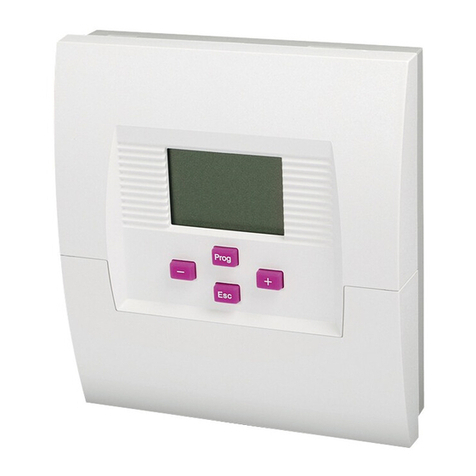
EbV elektronik CETA 101 User manual

Operating manual
101
Double differential temperature control
Version 1308-22
Art. 0450021015
0450021015_1308-22_BA_CETA101_EbV_EN.book Seite 1 Donnerstag, 21. Februar 2013 11:48 11

Scope of delivery ..............................................................................................................3
General ...............................................................................................................................3
Intended use .................................................................................................................... 3
Safety .................................................................................................................................3
General key functions ......................................................................................................4
Version display (when starting) .....................................................................................4
Basic display .....................................................................................................................5
Function with direct access ............................................................................................6
Menu level ......................................................................................................................... 7
Parameter description ................................................................................................... 10
Mounting .......................................................................................................................... 18
Terminal diagram ........................................................................................................... 19
Fault clearance ................................................................................................................20
Sensor resistance values .............................................................................................. 21
Declaration of conformity ..............................................................................................22
Technical Data ................................................................................................................23
Liability .............................................................................................................................23
Disposal ...........................................................................................................................24
© Elektronikbau- und Vertriebs GmbH
Heisterner Weg 8 - 12
D-57299 Burbach
This document may not be reproduced nor disclosed to third parties, particularly competitors, in original
or copy form without our prior explicit consent. The document is subject to our proprietary rights and
copyrights.
Any misuse is an infringement of the German Copyright Law of September 9, 1965, the law against
unfair competition, and the German Civil Code.
Contents
0450021015_1308-22_BA_CETA101_EbV_EN.book Seite 2 Donnerstag, 21. Februar 2013 11:48 11

3
Scope of delivery
1. 1x Central unit CETA 101
2. 1x Tank immersion sensor KVT 20/2/6
3. 2x Collector sensor PT1000/6
4. 8x Screw, plate 2,9x19 mm
5. 3x Screw assembly 4x35 mm
6. 3x Plug U6
7. 2 x Cable clamp
General
Systems with 2 heat sources and hot water tanks are controlled via the
differential temperature control. When the heat source temperature exceeds the
tank temperature by the value set on the controller, the circulation pump is
activated by the control and the heat absorbed in the heat source is transported
to the hot water tank.
Intended use
The unit is manufactured in accordance with state of the art technology and
approved safety regulations. Nevertheless, using the unit can cause danger to the
user or third persons, or damage to the unit and other assets. The unit must be
used exclusively as differential temperature controller.
Safety
All electrical connections, safety measures and protections have to be carried out
by an authorised professional electrician according to the valid standards and VDE-
guidelines, as well as the local regulations. The electrical connection must be a
fixed connection according to VDE 0100.
Hazard symbols in this operating manual
Hazard!
This symbol indicates information that warns of possible safety
risks or severe and fatal injuries!
0450021015_1308-22_BA_CETA101_EbV_EN.book Seite 3 Donnerstag, 21. Februar 2013 11:48 11

General key functions
4
1. General key functions
Prog
•Change selected submenus
•Change (parameter) setting
•Save value
+ (Plus) or - (Minus)
•Change parameter
•Change menu item
Esc
•Exit setting
•Keep old value
•Select next higher menu level
Esc-Lang
•Return to basic display
2. Version display (when starting)
c 101= Type designation Ceta 101
2.2= Version display (due to update it can
differ from example shown)
0450021015_1308-22_BA_CETA101_EbV_EN.book Seite 4 Donnerstag, 21. Februar 2013 11:48 11

5
Basic display
3. Basic display
Use + / - to switch to:
1= Basic display 1
80.5°C= Temperature F3 heat supplier 1 (e.g.
collector or solid fuel boiler)
44.0°C= Temperature F1 heat storage tank 1
ΔT1= Display pump function P1
ΔT2= Display pump function P2
Display burner block
2= Basic display 2
75.5°C= Temperature F4 heat supplier 2 (e.g.
collector or solid fuel boiler)
51.5°C= Temperature F2 heat storage tank 2
(if sensor F2 is available)
ΔT1= Display pump function P1
ΔT2= Display pump function P2
Display burner block
0450021015_1308-22_BA_CETA101_EbV_EN.book Seite 5 Donnerstag, 21. Februar 2013 11:48 11

Function with direct access
6
4. Function with direct access
Manual operation
— Activate by pressing and holding button
— Change pump function via buttons
and
— end function by pressing button
0...4
Controller is in manual mode
manual function
Function: The manual functions 0 ... 4 allow manual start-up of the system,
e.g. to perform venting.
0 = All relays OFF
1 = Pump ΔT1 ON
2 = Pump ΔT2 ON
3 = Pump ΔT1 + ΔT2 ON
4 = Pump ΔT1, ΔT2 and burner block relay ON
Important!
This function shall only be used by an authorised
professional. Temperatures are not monitored during manual
operation. Faulty operation or unsupervised operation of this
function may result in damages to the heating system.
+
0450021015_1308-22_BA_CETA101_EbV_EN.book Seite 6 Donnerstag, 21. Februar 2013 11:48 11

7
Menu level
5. Menu level
General menu structure Ceta series
Basic display
Prog
Esc
01
Menu 01
02
Menu 02
+-
27
Calibration
28
Relay test
02:01
Parameter 01
02:02
Parameter 02
02:nn
Last parameter
+-
+-
+
-
+
-
Prog
Select menu level
Select parameters
Esc
Value 1
Prog
Value 2
+-
Value n
+-
Set parameter value
Prog
Return
without
saving
Return
and save
Esc
0450021015_1308-22_BA_CETA101_EbV_EN.book Seite 7 Donnerstag, 21. Februar 2013 11:48 11

Menu level
8
Overview of menu level
X1: Only displayed during active heat balancing
X2: Function only in bus connection
Basic display
Prog
01
03
System
+-
08
27
28
03:01
08:01 08:02 08:03
Pump 'T1
on/off
+-
+-
+-
+
-
08:01 'T1 08:02 'T1 08:03 'T1
27:01 27:02 27:03
+
-
28:01
-
+
-
+
Prog
ESC
Prog
ESC
Prog
ESC
Prog
ESC
Prog
ESC
X1 X1
ESC
08:10 'T1 X2 08:11 'T1 X3
03:03
X3
08:04
08:04 'T1
08:12 'T1 08:13 'T1
03:06
X3 03:07 X3
09:03
X1
Pump 'T2
on/off
09:04 X1 09:07
Operating hours
of pump 2
'T1
28:02 28:03
27:04
09
+-
09:01 'T2 09:02 'T2 09:03 'T1
09:09 'T2
Burner block heat
generator
09:10 'T2
-
+
Prog
ESC
X2 X2
09:04 'T2
09:15 'T2
'T2
09:16 'T2
Changeover
sensor F2
09:05 X5
X5
08:21
08:22
Reversing the
thermostat
08:23
Info Heat capacity Heat balance Temperature
heat supplier
Temperature of heat
supplier 2
Temperature of heat
storage tank 2
Code entry Bus address Automatic exit time Anti-blocking
prot.pump
Operating mode Switch-on difference Switch-off difference Minimum running
time of pump
Inhibition heat
generator Heat balance On/Off Volume flow
HT-medium Density HT-medium
Switch-off temperature
thermostat
Frost protection
temperature
Operating mode Switch-on difference Switch-off difference Minimum running
time of pump
Inhibition heat
generator Reset counter
Calibration Calib. sensor F1 Calib. sensor F2 Calib. sensor F3 Calib. sensor F4
Relay test Relay test
output R1
Relay test
output R2
Relay test
output R3
0450021015_1308-22_BA_CETA101_EbV_EN.book Seite 8 Donnerstag, 21. Februar 2013 11:48 11

9
Menu level
X3: Are hidden when activating code 03:09
X5: Option
08:05 08:06 08:07 08:08
08:05 'T1 08:06 'T1 08:07 'T1 08:08 'T1
08:14 ΔT1
08:15 'T1
03:10
03:09 X3
09:08
Pump
'T2 starts
09:05 'T2 09:06 'T2 09:07 'T2 09:08 'T2
X5
08:19
08:18
08:09 'T1 X2
08:20
Switch-on temperature
thermostat
09:18
Heat exchange
function
09:19
Burner block
temperature
09:20
Switch-on temperature
thermostat
09:21
Switch-off temperature
thermostat
09:22
Reversing the
thermostat
09:23
Frost protection
temperature of F4
Temperature heat
storage tank Return temperature Pump operating
hours
Pump starts
Code heating
specialist Reset parameter
Min. temp. of
heat supplier
Max. temp. of
heat supplier
Final switch-off temp.
of heat supplier
Max. temp. of heat
storage tank
Burner block heat
generator
Heat capacity
HT-medium Reset counter Heat exchange
function
Burner block
temperature
Min. temp. of
heat supplier
Max. temp. of
heat supplier
Final switch-off temp.
of heat supplier
Max. temp. of heat
storage tank
0450021015_1308-22_BA_CETA101_EbV_EN.book Seite 9 Donnerstag, 21. Februar 2013 11:48 11

Parameter description
10
6. Parameter description
01 Information level
03 Parameter system
Display Designation Description
08:01 Heat capacity ΔT1 Current heat capacity in W X1
08:02 Heat balance ΔT1 Display of cumulative heat energy in kWh X1
08:03 Display pump
function ΔT1
0: Pump is switched off
1: Pump is switched on
08:04 Temperature
heat supplier ΔT1
Sensor temperature of heat supplier (e.g. collector, solid fuel
boiler) at input F3
08:05 Te m p e r a t u re
heat storage tank
ΔT1
Sensor temperature of heat storage tank at input F1
08:06 Temperature
return ΔT1
Sensor temperature of return at input F2, X5
if available.
08:07 Pump operating
hours ΔT1
Number of pump operating hours
08:08 Pump starts ΔT1 Number of pump starts
09:03 Display pump
function ΔT2
0: Pump is switched off
1: Pump is switched on
09:04 Temperature
heat supplier ΔT2
Sensor temperature of heat supplier (e.g. collector, solid fuel
boiler) at input F4
09:05 Te m p e r a t u re
heat storage tank
ΔT2
Sensor temperature of heat storage tank at input F1 X5
(or F2, if available)
09:07 Pump operating
hours ΔT2
Number of pump operating hours
09:08 Pump starts ΔT2 Number of pump starts
Display Designation Description
03:01 Code entry Setting range: 0 … 999
Factory setting: 0
Function: Show parameters marked with X3 if they are hidden by
the "Code heating specialist" 03:09.
0450021015_1308-22_BA_CETA101_EbV_EN.book Seite 10 Donnerstag, 21. Februar 2013 11:48 11

11
Parameter description
08 Parameter DeltaT1
03:03 Bus address Setting range: 21…25 X3
Factory setting: 21
Function: If more than one CETA 100 or 101 has to be connected
via data bus within a system, each unit must be set to a unique
address.
03:06 Automatic exit time Setting range: 0.5 … 10 min X3
Factory setting: 2 min
Function: when unit is not operated during the set time, the
display returns to basic display.
03:07 Anti-blocking
protection
Setting range: 0 = OFF X3
1 = ON
Factory setting: OFF
Function:
Pump is switched on 20 s daily during extended shutdown
(> 24h) as protection against blocking when function is activated.
03:09 Code heating
specialist
Setting range: 0 … 999
Factory setting: 0
Function:
Hide parameters marked with X3.
03:10 Total reset Reset to factory settings
Display Designation Description
08:01 Control mode ΔT1 Setting range: 0…3
Factory setting: 1
Function:
0 = OFF
1 = Delta-T without return flow sensor
2 = Delta-T with return flow sensor F2
3 = Thermostat function F1
08:02 Switch-on
differential ΔT1
Setting range: (Switch-off differential + 3K) … 30K
Factory setting: 10K
Function:
If temperate difference between sensors of heat supplier F3 and
heat storage tank F1 is larger than set value, the pump
switches on.
Display Designation Description
0450021015_1308-22_BA_CETA101_EbV_EN.book Seite 11 Donnerstag, 21. Februar 2013 11:48 11

Parameter description
12
08:03 Switch-off
differential ΔT1
Setting range: 2K … (Switch-on differential - 3K)
Factory setting: 5K
Function:
If temperate difference between sensors of heat supplier F3 and
heat storage tank F1 is smaller than set value, the pump
switches off.
08:04 Minimum pump
running time ΔT1
Setting range: OFF (----)
0.5 … 60 min
Factory setting: 3 min
Function:
Minimum switch-on time of pump per start.
08:05 Minimum
temperature heat
supplier ΔT1
Setting range: OFF (----)
5 … 80 °C
Factory setting: OFF
Function: Irrespective of switching differentials, the pump
switches on only after the sensor of heat supplier F3 has
exceeded the set value.
Note: The set minimum temperature has a fixed switching
hysteresis of 10K!
08:06 Maximum
temperature heat
supplier ΔT1
Setting range: OFF (----), 30 … 110 °C
Factory setting: 90°C
Function:
Irrespective of switching differentials, the pump performs a
forced switch on after the sensor of heat supplier F3 has
exceeded the set value.
08:07 Final switch-off
temperature heat
supplier ΔT1
Setting range: OFF (----), 70 … 210 °C
Factory setting: OFF
Function:
Irrespective of switching differentials, the pump performs a
forced switch off after the sensor of heat supplier F3 has
exceeded the set value.
08:08 Maximum
temperature heat
storage tank ΔT1
Setting range: OFF (----), 50 … 110 °C
Factory setting: 75°C
Function:
Irrespective of switching differentials, the pump performs a
forced switch off after the sensor of heat storage tank F1 has
exceeded the set value. This switch-off takes priority over
functions 08:07 and 08:06.
Display Designation Description
0450021015_1308-22_BA_CETA101_EbV_EN.book Seite 12 Donnerstag, 21. Februar 2013 11:48 11

13
Parameter description
08:09 Burner block
Heat generator ΔT1
Setting range: 0 ... 2 X2
Factory setting: 1
Function: 0 = OFF
1 = Burner block when pump is active
2 = Burner block only for DHW when pump
is active
08:10 Inhibition heat
generator ΔT1
Setting range: OFF (----) ... 24h X2
Function:
After burner block is active, the heat generator is also blocked for
the duration of the set time.
08:11 Activation heat
balance ΔT1
Setting range: OFF (----) X3, X5
1 = Heat balancing via return sensor on
F2 (option)
Factory setting: 1
Function:
The settings of parameters 08:12 to 08:14 are only active if the
heat balance function has been switched on via this parameter.
08:12 Volume flow HT-
medium ΔT1
Setting range: 0.0 … 30 l/min
Factory setting: 0.0 l/min
Function:
Here the volume flow is set in litre/minute when calculating flow
rate, according to respective pump capacity.
08:13 Density HT-medium
ΔT1
Setting range: 0.8 … 1.2 kg/l
Factory setting: 1.05 kg/l
Function:
Using this parameter, the density of the heat transfer medium is
entered in kilogramme per litre, according to manufacturer's data.
08:14 Heat capacity HT-
medium ΔT1
Setting range: 2.0 … 5.0 kJ/kgK
Factory setting: 3.6 kJ/kgK
Function:
This setting value is used to enter the specific heat capacity of
the heat transfer medium according to manufacturer's
information.
08:15 Reset counter ΔT1 Setting range: 0 = no reset, 1 = reset counter
Factory setting: 0
Function:
When value is changed to 1 and confirmed, all counters (heat
balance, operating hours and starts) are
reset.
Display Designation Description
0450021015_1308-22_BA_CETA101_EbV_EN.book Seite 13 Donnerstag, 21. Februar 2013 11:48 11

Parameter description
14
9 Parameter DeltaT2
08:18 Heat exchange
difference
Setting range: OFF (----), 5 ... 50K
Factory setting: OFF
Function:
If the F1 temperature is higher than 08:08 and the F3
temperature below 40°C, the pump will be switched on until the
F1 is lowered to the set difference below 08:08.
08:19 Burner block
temperature
Setting range: OFF (----), 5 ... 80 °C
Factory setting: OFF
Function:
Additionally or alternatively to 08:09, an F1 temperature can be
set whereby the burner block will be activated (via data bus).
When the temperature sinks below the value of 08:19 by 5K, it
will be deactivated.
08:20 Switch-on
temperature
thermostat
Setting range: 5 °C ... (switch-off temperature -3K)
Factory setting: 30 °C
Function:
If F1 sinks below the set value, the
Δ
T1 pump switches on.
08:21 Switch-off
temperature
thermostat
Setting range: (switch-on temperature +3K) ... 120 °C
Factory setting: 90 °C
Function:
If F1 exceeds the set value, the
Δ
T1 pump switches off.
08:22 Reversing the
thermostat
Setting range: 0, 1
Factory setting: 0
Function:
reverts the pump function. 0 = closer, 1 = opener
08:23 Frost protection
temperature of
sensor F3
Setting range: OFF, -15 °C ... 10 °C
Factory setting: OFF
Function:
When the F3 temperature is below the set value, the
Δ
T1 pump
will be switched on, and it will be switched off when the F3
temperature exceeds the set value by +2.5K.
Display Designation Description
09:01 Control mode ΔT2 Setting range: 0 , 1 , 3
Factory setting: 1
Function:
0 = Delta T2 OFF
1 = Delta T2 ON
3 = Thermostat function
Display Designation Description
0450021015_1308-22_BA_CETA101_EbV_EN.book Seite 14 Donnerstag, 21. Februar 2013 11:48 11

15
Parameter description
09:02 Switch-on
differential ΔT2
Setting range: (Switch-off differential + 3K) … 30K
Factory setting: 10K
Function:
If temperate difference between sensors of heat supplier F4 and
heat storage tank F2 is larger than set value, the pump
switches on.
09:03 Switch-off
differential ΔT2
Setting range: 2K … (Switch-on differential - 3K)
Factory setting: 5K
Function:
If temperate difference between sensors of heat supplier F4 and
heat storage tank F2 is smaller than set value, the pump
switches off.
09:04 Minimum running
time pump ΔT2
Setting range: OFF (----), 0.5 … 60 min
Factory setting: 3 min
Function:
Minimum switch-on time of pump per start.
09:05 Minimum
temperature heat
supplier ΔT2
Setting range: OFF (----), 5 … 80 °C
Factory setting: OFF
Function: Irrespective of switching differentials, the pump
switches on only after the sensor of heat supplier F4 has
exceeded the set value.
Note: The set minimum temperature has a fixed switching
hysteresis of 10K!
09:06 Maximum
temperature heat
supplier ΔT2
Setting range: OFF (----), 30 … 110 °C
Factory setting: 90°C
Function:
Irrespective of switching differentials, the pump performs a
forced switch on after the sensor of heat supplier F4 has
exceeded the set value.
09:07 Final switch-off
temperature heat
supplier ΔT2
Setting range: OFF (----), 70 … 210 °C
Factory setting: OFF
Function:
Irrespective of switching differentials, the pump performs a
forced switch off after the sensor of heat supplier F4 has
exceeded the set value.
09:08 Maximum
temperature heat
storage tank ΔT2
Setting range: OFF (----), 50 … 110 °C
Factory setting: 75°C
Function:
Irrespective of switching differentials, the pump performs a forced
switch off after the sensor of heat storage tank F1 (optionally F2, if
available) has exceeded the set value. This switch-off takes
priority over functions 08:07 and 08:06.
Display Designation Description
0450021015_1308-22_BA_CETA101_EbV_EN.book Seite 15 Donnerstag, 21. Februar 2013 11:48 11

Parameter description
16
09:09 Burner block
Heat generator ΔT2
Setting range: 0 ... 2 X2
Factory setting: 1
Function: 0 = OFF
1 = Burner block when pump is active
2 = Burner block only for DHW when pump
is active
09:10 Inhibition heat
generator ΔT2
Setting range: OFF (----) ... 24h X2
Factory setting: OFF
Function:
After burner block is active, the heat generator is also blocked for
the duration of the set time.
09:15 Reset counter ΔT2 Setting range: 0 = no reset, 1 = reset counter
Factory setting: 0
Function:
When value is changed to 1 and confirmed, all counters (Delta T2
pump, operating hours and starts) are reset.
09:16 Changeover
Sensor F2
Setting range: 1, 2 X5
Factory setting: 1
Function: 1 = Sensor F2 (option) is return flow sensor
and both Delta-T controls adjust to sensor
heat storage tank 1 (F1)
2 = Sensor F2 (option) is the sensor of heat
storage tank 2
09:18 Heat exchange
difference
Setting range: OFF (----), 5 ... 50K
Factory setting: OFF
Function:
If the F2 temperature is higher than 09:08 and the F4
temperature is below 40 °C, the
Δ
T2 pump will be switched on
until the F2 is lowered to the set difference below 09:08.
09:19 Burner block
temperature
Setting range: OFF (----), 5 ... 80 °C
Factory setting: OFF
Function:
Additionally or alternatively to 09:09, an F2 temperature can be
set whereby the burner block will be activated (via data bus).
When the temperature sinks below the value of 09:19 by 5K, it
will be deactivated.
09:20 Switch-on
temperature
thermostat
Setting range: 5 °C ... (switch-off temperature -3K)
Factory setting: 30 °C
Function: If F1 (F2) sinks below the set value, the
Δ
T2 pump
switches on.
Display Designation Description
0450021015_1308-22_BA_CETA101_EbV_EN.book Seite 16 Donnerstag, 21. Februar 2013 11:48 11

17
Parameter description
27 Sensor calibration
28 Relay test
09:21 Switch-off
temperature
thermostat
Setting range: (switch-off temperature +3K) ... 120 °C
Factory setting: 90 °C
Function: If F1 (F2) sinks below the set value, the
Δ
T2 pump
switches off.
09:22 Reversing the
thermostat
Setting range: 0, 1
Factory setting: 0
Function:
reverts the pump function. 0 = closer, 1 = opener
09:23 Frost protection
temperature of
sensor F4
Setting range: OFF, -15 °C ... 10 °C
Factory setting: OFF
Function:
When the F4 temperature is below the set value, the
Δ
T2 pump
will be switched on, and it will be switched off when the F4
temperature exceeds the set value by +2.5K.
Display Designation Description
27:01 Calibration F1 Setting range: -5K … +5K
Factory setting: 0K
Function: Correction of measured sensor value on
Input heat storage tank F1
27:02 Calibration F2 See 27:01 on input return heat storage tank F2 (option)
27:03 Calibration F3 See 27:01 on input heat supplier F3
27:04 Calibration F4 See 27:01 on input heat supplier F4
Display Designation Description
28:01 Test pump output
Delta T1
Setting range: 0 = OFF
1 = ON
Factory setting: 0
Function:
By changing the value, the output switches on and off (test
function), independent of function.
28:02 Test pump output
Delta T2
see 28:01
28:03 Test output
Burner block
see 28:01
Display Designation Description
0450021015_1308-22_BA_CETA101_EbV_EN.book Seite 17 Donnerstag, 21. Februar 2013 11:48 11

Mounting
18
7. Mounting
Drilling pattern for wall fastening
Rail mount
Hazard!
Installation must be performed only by an authorised professional
electrician! Ensure that unit is de-energised before opening it!
1. Remove terminal area cover from
casing.
2. For mounting, first put a screw
into the wall.
3. Hang controller into the opening.
4. Use controller as template for the
other screw holes.
1. Insert mounting feet into rail
mount opening.
2. Lock hook in place by pushing
down.
0450021015_1308-22_BA_CETA101_EbV_EN.book Seite 18 Donnerstag, 21. Februar 2013 11:48 11

19
Terminal diagram
8. Terminal diagram
Hazard!
Connection must be performed only by an authorised professional
electrician! Ensure that unit is de-energised before opening it!
230V connections Low voltage connections
L=Phase 230V mains
1=L1 (230V) Connection Delta T1 pump
2=L1 (230V) Connection Delta T2 pump
Connection without function
N=Neutral 230V mains, pumps
Connection burner block (isolated)
=Ground connection
Bus connections for networking (see parameter 03:03)
Connections without function
Connections for Ceta RC (option)
F1=Sensor heat storage tank Delta-T1 (KVT20)
F2=Sensor heat storage tank Delta T2/
return flow Delta T1 (KVT20), (option)
F3=Sensor heat supplier Delta-T1 (PT1000)
F4=Sensor heat supplier Delta-T2 (PT1000)
0450021015_1308-22_BA_CETA101_EbV_EN.book Seite 19 Donnerstag, 21. Februar 2013 11:48 11

Fault clearance
20
9. Fault clearance
To allow an accurate diagnosis in case of malfunction, the unit is equipped with
a fault display system. The faults are shown on the basic display of the unit in
form of an error code:
Use + / - to switch to:
Fault overview:
A corresponding fault code is shown alternately in the lower display:
1 = Display 1
0---°C = Sensor F3 Heat supplier 1 (z.B. collector1,
solid fuel boiler1) is interrupted
1---°C = Sensor F1 heat storage tank 1 has short
circuit
2 = Display 2
1---°C = Sensor F4 Heat supplier 2 (e.g.
collector2, solid fuel boiler2) has short
circuit
0---°C = Sensor F2 (option) heat storage tank 2 is
interrupted
Fault code Cause Repair
0--- Sensor F1, F2 or F3 interruption Check cable and plug connection;
repair if necessary
1--- Sensor F1, F2 or F3 short circuit Replace sensor
Fault Cause Repair
Display text not visible No power, defective fuse in unit Check cable and plug connection;
repair if necessary; replace fuse
Fault code Cause Repair
11-0 Interruption sensor F1 Check cable and plug connection;
replace if necessary
11-1 Short circuit sensor F1 Replace tank sensor
12-0 Interruption sensor F2 See 11-0
12-1 Short circuit sensor F2 See 11-1
13-0 Interruption sensor F3 See 11-0
0450021015_1308-22_BA_CETA101_EbV_EN.book Seite 20 Donnerstag, 21. Februar 2013 11:48 11
Table of contents
Other EbV elektronik Temperature Controllers manuals
