DIFFERENTIAL TEMPERATURE CONTROLLER
FOR SOLAR HEATING WITH TWO
SOLAR BACKING
Ver. 02
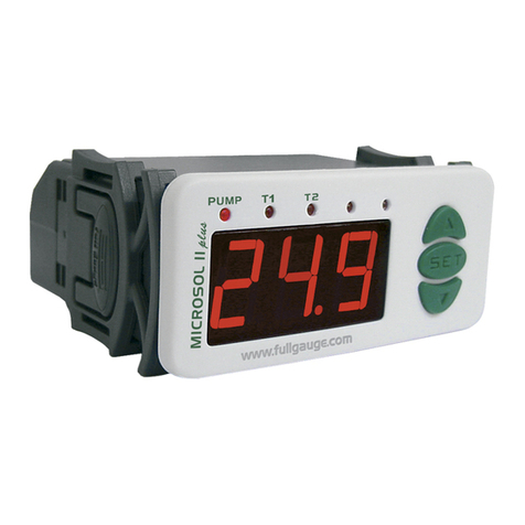
MICROSOL II plus
MCSOL2V02-05T-10793
UL-Underwriters Laboratories
1.DESCRIPTION
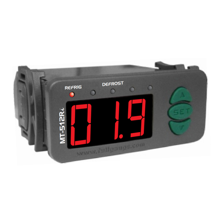
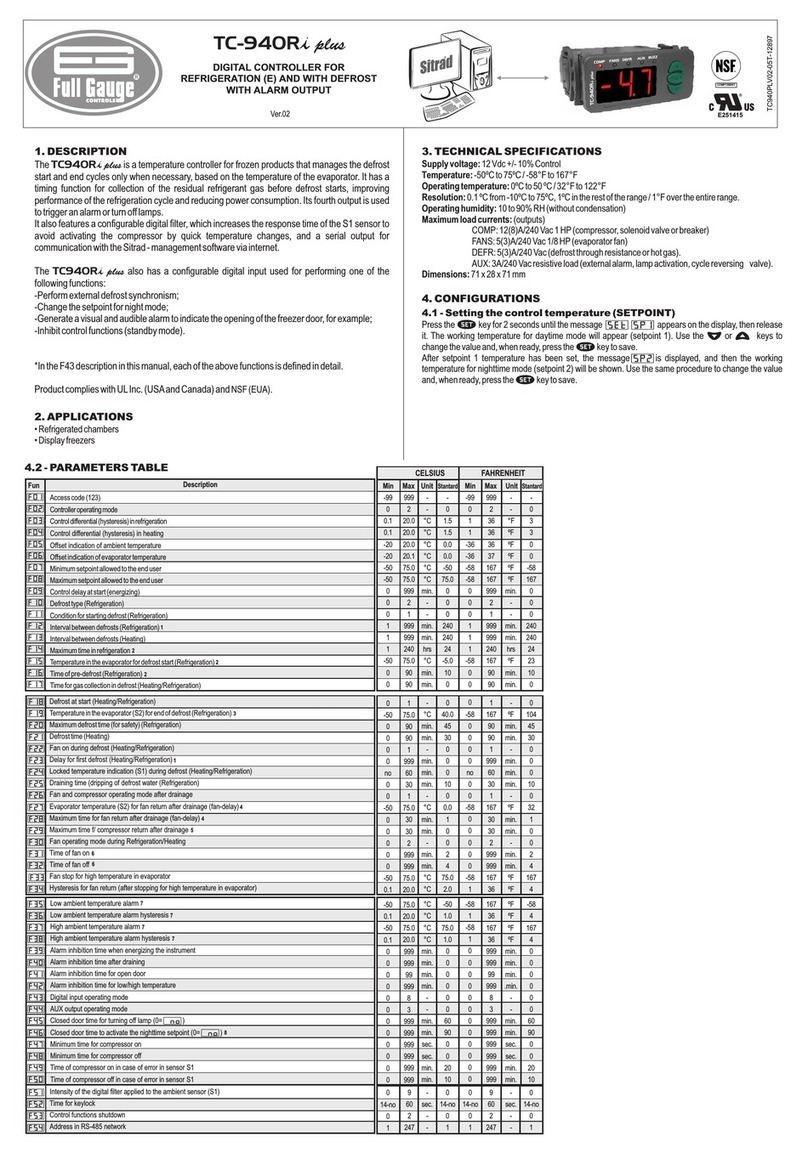
Differential temperature controller for automation of solar heating systems,
becomes simple the management of the temperature of the water in the thermal reservoirs and
swimmingpools,usethesolarenergybetter..
Itactsinthecommandofthewatercirculationpumpthroughthedifferentialoftemperaturebetweenthe
solarcollectors andthe thermal reservoiror swimming pool.It is adedicated instrumentthat has allits
parametersofconfigurationprotectedbyaccesscode.
It makes use of two solar backings outputs, that can be electric, gas, diesel or also to program the
filteringoftheswimmingpool.solarbacking1istiedwithanschedulethatallowstheconfigurationofup
to four daily events for each day of the week and solar backing 2 can optionally be configured for
functioninginsetwiththeschedule.
Ithas functionsthat preventthewater freezingand overheatingin thetubings anda clockwith internal
batterytoguaranteeitssynchronism,evenintheenergylack,permanyyears.Theinstrumenthasserial
communicationforconnectionwiththeSITRAD viaInternet.
ProductcomplieswithCE(EuropeanUnion)andULInc.(UnitedStatesandCanada).
•Solarheatingpumpedsystems
MICROSOL II plus
®
2.APPLICATION
3.TECHNICALSPECIFICATIONS
-Powersupply:
-Controltemperature:
-Resolution:
-Dimensions:
-Operatingtemperature:
-Operatinghumidity:
-Sensors:
-Controloutputs:
CLASSIFICATIONACCORDINGTOIEC60730-2-9STANDARD:
-Temperaturelimitoftheinstallationsurface:
-Typeofconstruction:
-Automaticaction:
115or230Vac±10%(50/60Hz)
-50to105°
-58to221ºF
0.1°Cbetween-10and100°Cand1°Cintherestoftherange
1°Fbetween-58and221°F
71x28x71mm
0to50°C/32to122°F
10to90%RH(withoutcondensation)
S1-Sensorofthecollectors
S2-SensoroftheReservoir/Pool
S3-Sensorforcontrolofsolarbackings
PUMP-Waterpumporsolenoid-5(3)A/250Vac1/8HP
AUX1-solarbacking1-5(3)A/250Vac1/8HP
AUX2-solarbacking2-5(3)A/250Vac1/8HP
50°C
Built-inelectroniccontroller
Type1
-Controlofpollution:
-Impulsevoltage:
-Temperatureforthetestofspherepressure:
-Insulation:
Level2
1,5kV 75°Cand125°C
ClassII
Press and simultaneously for two seconds until it appears , then releasing it. When
appears press (tap) and enter the code (123) through keys and . To confirm,
pressthekey .Throughthekeys and accesstheotherfunctionsandproceedinthesame
manner to adjust them. To leave the menu and return to normal operations, press (long hit) until
appears.
Accesscodeentry
Advancedconfigurationfunctions
Eventsplanneroperatingmode
Schedulingintheeventsplanner
Adjustmentoftheclockandthedayoftheweek
4.CONFIGURATIONS
4.1-Toenterintothefunctionsmenu
4.2-Functions
SET
SET
SET
4.2.1-Parameters table
Description Min Max Unit
CELSIUS
Fun
Standard Standard
Min Max Unid
FAHRENHEIT
-
1.0
1.0
0
3.0
0.0
0.1
0.0
0.1
0.1
-
20.0
20.0
999
10.0
99.9
20.0
99.9
20.0
20.0
-
°C
°C
sec.
°C
°C
°C
°C
°C
°C
-
8.0
4.0
0
3.0
99.9
99.9
1.0
1.0
1.0
-
°F
°F
sec.
°F
°F
°F
°F
°F
°F
-
36
36
999
50
212
36
212
36
36
-
2
2
0
38
32
32
1
1
1
-
14
7
0
38
212
212
1
1
1
Indication of the preferential temperature
Differential for turning on the water circulation pump
Differential for turning off the water circulation pump
Minimum time for the pump off
Temperature of the antifreeze for sensor 1
to turn the water circulation pump on
Overheat temperature for sensor 1
to turn the water circulation pump off
Overheated hysteresis for sensor 1
for turning the water circulation pump back on
Overheat temperature for sensor 2
to turn the water circulation pump off
Overheated hysteresis for sensor 2
for turning the water circulation pump back on
Hysteresis of the solar backing 1 operation
Minimum setpoint of the solar backing 1 operation
Maximum setpoint of the solar backing 1 operation
Manual activation time for solar backing 1
Solar backing 2 operation mode
Hysteresis of the solar backing 2 operation
Minimum setpoint of the solar backing 2 operation
Maximum setpoint of the solar backing 2 operation
Cyclical timer time on
Cyclical timer time off
Method for linking the solar backings to the events schedule
Indication offset for the temperature of the sensor 1
Indication offset for the temperature of the sensor 2
Indication offset for the temperature of the sensor 3
Address of the instrument on the RS-485 network
-50.0
-50.0
0
0
0.1
-50.0
-50.0
1
1
0
-5.0
-5.0
-5.0
1
105.0
105.0
999
5
20.0
105.0
105.0
999
999
3
5.0
5.0
5.0
247
°C
°C
min.
-
°C
°C
°C
min.
min.
-
°C
°C
°C
-
-58
-58
0
0
1
-58
-58
1
1
0
-9
-9
-9
1
221
221
999
5
36
221
221
999
999
3
9
9
9
247
°F
°F
min.
-
°F
°F
°F
min.
min.
-
°F
°F
°F
-
-58
1
0
0
0
0
1
221
0
0
1
-58
221
1
-50.0
1
0
0.0
0.0
0.0
1
105.0
0
0
1.0
-50.0
105.0
1
4.2.2 - Parameters description
Thisfunctionallowsthepreferentialtemperatureindicationtobeconfigured.Youmaychoosebetween:
temperatureinthesensor1
temperatureinthesensor2
temperatureinthesensor3
differentialtemperature(S1-S2)
Thisfunctionallowstheadjustmentofthedifferentialtemperature(S1-S2)toactivatethewatercirculation
pump. As the solar collectors receive energy, the temperature in sensor S1 increases. When this
temperatureisatavalueestablishedasbeingabovethetemperatureofsensorS2,thepumpisturnedon
andcirculatesundertheheatedwater,storingitinthereservoir,forexample.
Thisfunction allowsthe adjustmentof the differentialtemperature(S1-S2) toturnoffthe watercirculation
pump. With the pump on, the hot water circulates below and cools upwards. After which time, the
temperaturedifferencebetweenS1andS2tendstodecrease.Whenthisdifferencefallstoanestablished
level,thepumpisturnedoffandthewatercirculationstops.
Indicationofthepreferentialtemperature
Differentialforturningonthewatercirculationpump
Differentialforturningoffthewatercirculationpump
Thisfunctionallowstheadjustmentoftheminimumtimeoffthatthepumpshouldhavebeforebeingturned
on again. This option avoids the pump from being turned on and off in short periods of time, which thus
increasestheusefullifethereof.Thisfunctionalsodefinesthedelayinthepump'sactivationonturningon
thecontroller.
Thisfunctionallowsadjustmenttothetemperatureforformingiceinthecollectors.Whenthetemperature
in the collectors (sensor 1) are very low (Ex.: winter nights), the pump is turned on from time to time, to
prevent the water from freezing in the pipes and damaging them. The hysteresis is set at 2°C/4°F. To
deactivatethisfunctiondecreasethevalueuntilthemessage appearsinthedisplay.
This function allows the adjustment of the overheating temperature of the collectors, to turn off the water
circulation pump. When the temperature in the collectors (sensor 1) is above an established value, the
pumpisturnedofftokeeptheoverheatedwater fromcirculatingthroughthe pipesanddamagingthem (if
PVCpipesareused).
Adjustment of the hysteresis of the overheated temperature of sensor 1 to allow the water pump to be
turnedonagain.
Minimumtimeforthepumpoff
Temperatureoftheantifreezeforsensor1toturnthewatercirculationpumpon
Overheattemperatureforsensor1toturnthewatercirculationpumpoff
Overheatinghysteresisofsensor1toreconnectthewatercirculationpump
Overheattemperatureforsensor2toturnthewatercirculationpumpoff
Overheatedhysteresisforsensor2forturningthewatercirculationpumpbackon
Hysteresisofthesolarbacking1operation
Minimumsetpointofthesolarbacking1operation
Maximumsetpointofthesolarbacking1operation
This function allows the adjustment of the overheating temperature of the pool to turn the water
circulationpumpoff,avoidingthermaldiscomfort.
Adjustmentofthe hysteresisofthe overheatedtemperatureofsensor2 toallowthe waterpumpto be
turnedonagain.
Adjustmentofthehysteresisfortheactivationtemperaturesetpointforsolarbacking1.
Lower limit, the purpose of which is to avoid the accidental regulation of temperatures far below the
setpointofsolarbacking1.
Upper limit, the purpose of which is to avoid the accidental regulation of temperatures far above the
setpointofsolarbacking1.
