manuals.online logo
Brands
  1. Home
  2. •
  3. Brands
  4. •
  5. alre
  6. •
  7. Temperature Controllers
  8. •
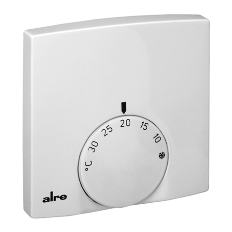
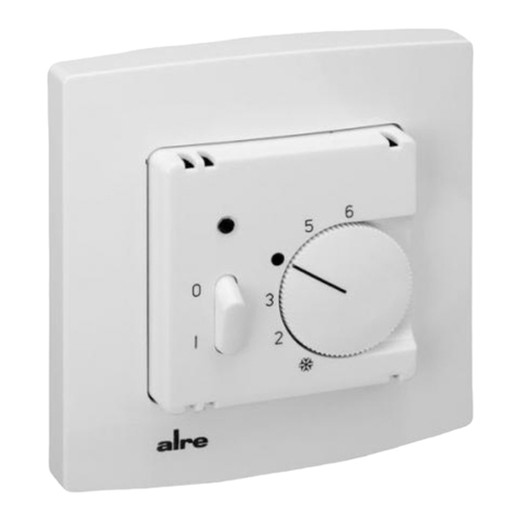
  9. alre FTR 101.2 Series User manual

alre FTR 101.2 Series User manual

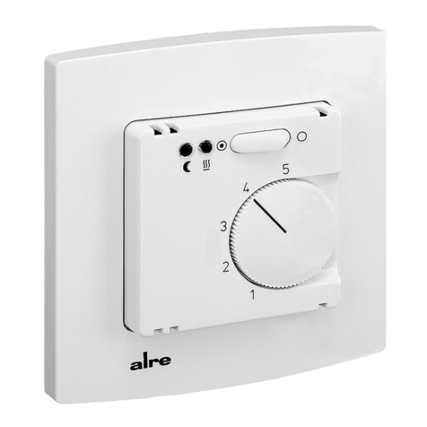
FTR 101.2xx
Stand 4.2013 (13/021) 1 4 12 522 03
24V~ Raumtemperaturregler Bimetall Unterputz im Flächenschalterrahmen
24V~ Bimetal room temperature controller for flush installation in a flush mounted switch frame
Régulateur de température ambiante 24V~ avec capteur à bilame –
pour l’installation encastrée dans un cadre de recouvrement plat
Биметаллический регулятор температуры помещения 24
V~
для скрытого монтажа в рамке для
поверхностного выключателя
Expert electricians only may open this device in due compliance with the wiring diagram
shown in the housing cover / on the housing / represented in the corresponding operating
instructions. All expert electricians charged with the execution of such works must comply
with the relevant safety regulations currently operative and in force. The company charged
with the installation of the device must, after the completion of the installation works,
instruct the user of the control system into its functions and in how to operate it correctly.
These operating instructions must be kept at a place that can be accessed freely by the
operating and/or servicing personnel in charge.
Sicherheitshinweis! Safety information!
Dieses Gerät darf nur durch eine Elektrofachkraft geöffnet und gemäß dem entsprechenden
Schaltbild im Gehäusedeckel / auf dem Gehäuse / in der Bedienungsanleitung installiert
werden. Dabei sind die bestehenden Sicherheitsvorschriften zu beachten. Nach der Instal-
lation ist der Betreiber, durch die ausführende Installationsfirma, in die Funktion und Bedie-
nung der Regelung einzuweisen. Die Bedienungsanleitung muss für Bedien- und Wartungs-
personal an frei zugänglicher Stelle aufbewahrt werden.
1. Anwendung 1. Application
This room temperature controller has been specially devised for the control and supervision
of temperatures in offices, living spaces and hotels. For the triggering of electric floor hea-
ting systems a power contactor is needed in addition. Regarding floor heating systems,
care must be taken to ensure that the performance of the controlled system cannot, even
if the system is operated continuously, result in an overheating of the pavement. With hot-
water heating systems, no more than 5 normally closed valves must be used.
Caution: The controller model FTR 101.265 has been specially developed for the control
of two-pipe climate systems. The imprint on its heating/cooling changeover switch relates
to normally closed valves only. Where applicable, temperature limiters need to be installed
in addition. Regarding other applications not to be foreseen by the manufacturer of this
device, the safety standards these applications need to be followed and adhered to. Regar-
ding the aptitude of the device for any such application, please refer to section 7. herein.
Dieser Raumtemperaturregler wurde speziell für die Regelung oder Überwachung von Tem-
peraturen in Büros, Wohnräumen und Hotels entwickelt. Elektrische Fußbodenheizungen
müssen über ein zusätzliches Leistungsschütz angesteuert werden. Hierbei ist darauf zu
achten, dass die Leistung der Heizung auch bei Dauerbetrieb den Estrich nicht überhitzen
kann. Bei Warmwasserheizungen oder Wasserkühlung sind maximal 5 stromlos geschlos-
sene Ventile zu verwenden.
Achtung! Bei dem speziell für 2-Rohr-Klimasysteme entwickelten Reglertyp FTR 101.265,
ist die Bedruckung des Heiz-/Kühl-Umschalters auf stromlos geschlossene Ventile ausge-
legt.
Gegebenenfalls benötigte Temperaturbegrenzungen müssen zusätzlich installiert werden.
Für andere, vom Hersteller nicht vorherzusehende Einsatzgebiete, sind die dort gültigen
Sicherheitsvorschriften zu beachten. Eignung hierfür siehe Punkt 7. Gewährleistung.
3. Installation / Montage 3. Mounting / Installation
Je nach Gerätetyp oder Verpackungsgröße, wird das Gerät entweder geschlossen oder der
schnelleren Montage wegen geöffnet ausgeliefert. Für die Befestigungsschraube ist je nach
verwendeter Schraube ein PZ 1 bzw. T7 Schraubendreher zu verwenden. Das Gerät mit
dem 50 x 50 mm Gehäusedeckel ist mittels Zwischenrahmen der Schalterhersteller nach
DIN 49075 in nahezu alle Schalterprogramme integrierbar. Das Gerät mit dem 55 x 55 mm
Gehäusedeckel ist ebenfalls für diverse Schalterprogramme geeignet. Bei Mehrfachrahmen
ist der Regler immer an unterster Stelle zu montieren. Der Regler ist zur Montage in die
UP-Dose bestimmt und darf nicht direkt Wärme- oder Kältequellen ausgesetzt werden. Es
ist darauf zu achten, dass der Regler auch rückseitig keiner Fremderwärmung oder -küh-
lung, z.B. bei Hohlwänden durch Zugluft oder Steigleitungen ausgesetzt wird.
2. Funktionen
Der Raumtemperaturregler erfasst mit einem innenliegenden Bimetallfühler die Raumtem-
peratur und regelt entsprechend dem eingestellten Sollwert. Die einzelnen Reglertypen un-
terscheiden sich durch die Ausstattung, wie Schalter „Ein / Aus“ und Lampe rot „Heizen“
(Typ .062), Schalter und Lampe rot „Ein / Aus“ (Typ .073), Schalter „Heizen/Kühlen“ (Typ
.065) sowie Schalter „Absenken/Komfort/Automatik“ und Lampe grün „Nachtabsenkung“
(Typ .075)
2.1 Thermische Rückführung
Da während des Heiz- oder Kühlvorgangs der Regler die Raumtemperatur erst relativ spät
erfasst, wird mittels einer thermischen Rückführung der Regler rechtzeitig zum Ausschalten
angeregt und so eine sehr genaue Schaltdifferenz erreicht.
2.2 Bereichseinengung
Mittels der sich unter dem Knopf befindlichen Einstellfahnen kann der Einstellbereich me-
chanisch begrenzt werden. (siehe Punkt 3.).
2.3 ECO-Betrieb (Nachtabsenkung)
Bei Reglern mit ECO-Betrieb (Uhrensymbol im Anschluss-Schaltbild) wird bei Beschalten
der Klemme mit 24 V~/4auf eine um ca. 4K geringere Temperatur geregelt.
2. Functional description
The room temperature controller described herein is equipped with an internal bimetal sensor
that captures the currently existing room temperature. The device controls the related heating
or cooling system in accordance with the adjusted set value. The individual controller models
differ by the different components they are endued with, such as “ON/OFF” switches, red
lamps for heating mode indication (type version .062), switches with red “ON/OFF” indicator
lamp (type version .073), “heating/cooling” mode changeover switches (type version .065),
“temperature decrease / comfort mode / automatic mode” selector switches and green “night
temperature decrease mode” indicator lamps (type version .075).
2.1 Thermal recirculation
As, during the heating or cooling procedure, the controller usually captures the actually pre-
vailing room temperature at a rather late point, a thermal recirculation has been realised with
the device that enables to excite it early enough with the consequence that a very precise
switching difference can be attained.
2.2 Suppression of the setting range
The setting elements (pins) located underneath of the knob enable to delimit the setting
range mechanically (see section 3.).
2.3 ECO mode (night temperature decrease mode)
With all controller models that enable to operate in ECO mode (indicated by the clock symbol
shown in the connection diagram), the room temperature is decreased by approx. 4K when
connecting the
24 V~/4
power supply to the terminal .
Zum Öffnen des Reglers ist die Schraube nach Abziehen des Einstellknopfes zu lösen und
die Reglerkappe inklusive Rahmen abzunehmen. Nach elektrischem Anschluss und Mon-
tage in die UP-Dose, ist der Regler in umgekehrter Reihenfolge wieder zu schließen.
To open the controller, remove the adjusting knob first, then loosen the screw and remove
the controller cap. After its electrical connection and installation in the UP box, the closing
of the controller takes place in inverse order.
The device is, depending on the type version of the device or size of the package used for it,
either delivered in closed or, in order to facilitate its fast installation, also in opened conditi-
on. The device with the 50x50mm housing cover can be integrated into almost all currently
available flush switch installation frame systems when using DIN 49075 compliant inter-
mediate frames. The device with the 50x50mm housing cover is likewise suited for use
with different commercially available switch lines. Depending on the type of screw used,
either a PZ1 or T7 screwdriver needs to be used for the fastening of the cover fixing screw.
If using multiple frames, the controller must always be mounted in the lowest position. The
controller is determined for installation on an UP box and must not be exposed to any heat
or cold sources whatsoever. Also care must be taken to ensure that it is not exposed to the
influence of heat or cold sources that warm or cool the device at its back (through air flows
in cavity walls or the temperatures radiated by ascending pipelines, f. ex.).
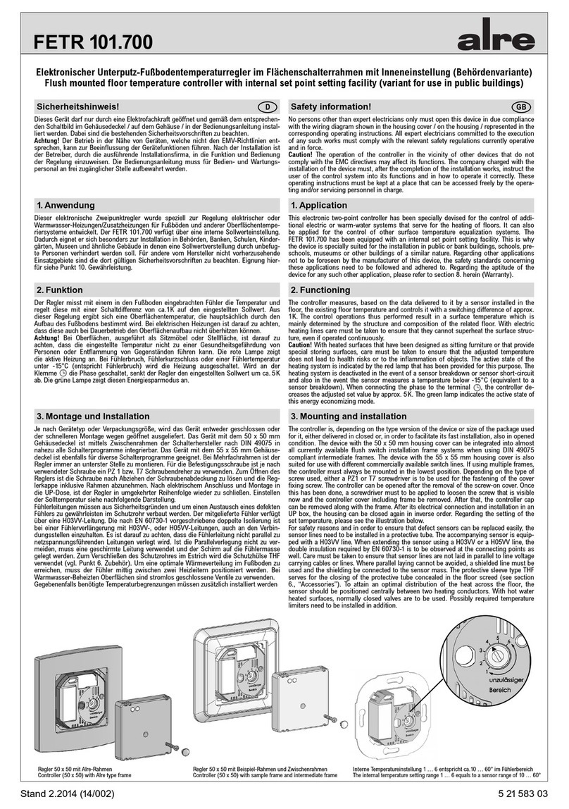
Regler 50 x 50 mit Standard-Rahmen
Controller (50 x 50) with standard type frame Regler 50 x 50 mit Beispiel-Rahmen und Zwischenrahmen
Controller (50 x 50) with sample frame and intermediate frame Regler 55 x 55 mit Beispiel-Rahmen
Controller (55 x 55) with sample frame
GBD
Um den Einstellbereich Einzuengen, wird der sich unter dem Einstellknopf befindliche Stift
abgezogen und die Einstellfahnen verstellt (rot für maximal und blau für minimal mögliche
Einstellung). Anschließend wird der Stift wieder eingesteckt und somit die Begrenzungen
arretiert.
5. Klemmen- und Bediensymbole 5. Terminal and control symbols
Bediensymbole
IEin
0Aus
Automatikbetrieb
Komfortbetrieb
ECO-Betrieb (Nachtabsenkung)
Betriebsart Heizen
(am Schalter) Betriebsart Kühlen
(an der Skala) Frostschutzstern (entspricht ca. 5°C)
Wohlfühlpunkt (entspricht ca. 20°C)
Klemmensymbole
LPhase Betriebsspannung
NNeutralleiter Betriebsspannung
Ausgang Heizen
Ausgang Kühlen
ECO-Eingang (Nachtabsenkeingang)
Control symbols
ION
0OFF
Automatic mode
Comfort mode
ECO mode (night temperature decrease mode)
Heating mode
(at the switch) Cooling mode
(at the scale) Frost protection system (equivalent to approx. 5°C)
Well-being point (equivalent to approx. 20°C)
Terminal symbols
LOperating voltage (phase)
NOperating voltage (neutral conductor)
Output “heating”
Output “cooling”
Temperature decrease input (ECO input)
4. Technische Daten
Fühlerelement: Bimetall, Typ 1C
Versorgungsspannung und Schaltspannung: 24V~/4
Heizkontakt: 1(1)A
Kühlkontakt: 1(1)A
Regelbereich: 5 … 30°C
Schaltdifferenz: ca. 0,5K
Skala: Merkziffernskala ( 2 3 5 6)
max. zulässige Temperatur-Änderungs-
geschwindigkeit der Regelstrecke: 4K/h
Schutzart: IP30 nach entsprechender Montage
Schutzklasse: III
max. zulässige Luftfeuchtigkeit: 95%rH, nicht kondensierend
Gehäuse: Berlin Unterputz
Gehäusematerial und -Farbe: Kunststoff Polycarbonat (PC),
reinweiß (ähnlich RAL 9010)
Approbation: VDE siehe Geräteaufdruck
4. Technical data
Sensing element: bimetal sensor, type 1C
Supply and switching voltage: 24V~/4
Heating contact: 1(1)A
Cooling contact: 1(1)A
Control range: 5 … 30°C
Switching difference: approx. 0.5K
Scale: note numeral scale ( 2 3 5 6)
Max. admissible temperature changing
speed of the controlled system: 4K/H
Degree of protection: IP30 (after according installation)
Protection class: III
Max. admissible air moisture: 95% r.h., non condensing
Housing: design Berlin “UP”
Housing material and colour: plastic (polycarbonate), pure white
(similar to RAL 9010)
Certification: VDE, see housing imprint
Einstellfahne für
maximalen
Temperaturwert
Einstellfahne für
minimalen
Temperaturwert
Setting pin for
maximum
temperature
limitation
Setting pin for
minimum
temperature
limitation
The setting pins located underneath of the adjusting knob enable to delimit the setting ran-
ge
of the controller mechanically. To enable this, the adjusting knob must be removed by
pulling it off and, after the adjustment of the related pins (end stops, red for max. and blue
for min. setting) be put on again in order to lock the limitations.
Только специалисту-электрику разрешается открывать данное устройство и осуществлять
его установку согласно соответствующей схеме соединений на крышке корпуса / корпусе
/ в руководстве по эксплуатации. При этом должны выполняться существующие правила
техники безопасности. Фирма, осуществившая установку устройства, проводит затем
инструктаж персонала эксплуатационной организации по вопросам функционирования
и обслуживания регулятора. Руководство по эксплуатации должно храниться в месте,
легкодоступном для обслуживающего персонала и специалистов по техобслуживанию.
Consigne de sécurité
Указание по безопасности
RUS
Uniquement des personnes qualifiées en matière d’électricité doivent ouvrir ce dispositif
en conformité avec le schéma des connexions représenté dans le couvercle du boîtier /
apposé sur le boîtier / représenté dans les notices d’instructions. Tous électriciens spé-
cialisés chargés de l’exécution de tels travaux doivent se conformer aux prescriptions de
sécurité actuellement en vigueur s’y rapportant. La société chargée de l’installation du dis-
positif doit, après l’achèvement des travaux, initier l’utilisateur aux fonctions du régulateur
et à son opération correcte. Toujours garder cette notice d’instructions à un lieu librement
accessible pour les opérateurs et hommes de service.
1. Application 1.
Применение
Этот регулятор температуры помещения был специально разработан для регулирования
и контроля температуры в офисах, жилых помещениях и гостиницах. Электрические
теплые полы должны иметь дополнительный силовой контактор. При этом следить за тем,
чтобы из-за мощности отопления также и в длительном режиме работы не перегревался
бесшовный пол. В случае водяного отопления или водяного охлаждения использовать не
более 5 закрытых в обесточенном состоянии клапанов.
Внимание! У регулятора типа
FTR 101.265
, разработанного специально для 2-трубных
систем кондиционирования, отметки на переключателе нагрева/охлаждения рассчитаны
на закрытые в обесточенном состоянии клапаны. Возможно необходимые ограничители
температуры должны быть установлены дополнительно. Для других, не предусмотренных
производителем областей применения необходимо соблюдать правила техники
безопасности, действующие в соответствующей области. Пригодность для этого см. в
пункте 7. Гарантия.
Ce régulateur de température ambiante a été spécialement conçu pour le réglage ou surveil-
lance de températures dans des bureaux, habitations et hôtels. Des systèmes de chauffage
par le sol électriques doivent être excités par un contacteur de puissance additionnel. Avec
ces systèmes il faut veiller à assurer à ce que la puissance du système contrôlé ne puis-
se, même si le système est opéré en marche continue, résulter dans une surchauffe de la
structure superficielle correspondante. Avec des systèmes de chauffage à eau chaude ou de
refroidissement à eau ne plus que 5 soupapes du type normalement fermées doivent être
utilisées. Attention! Avec le type de régulateur FTR 101.265 spécialement conçu pour le ré-
glage de systèmes de climatisation à 2 conduites, l’empreinte sur le commutateur inverseur
«chauffer/refroidir» se réfère aux soupapes du type normalement fermé. Le cas échéant,
l’installation de limitateurs de température est nécessaire de plus. En ce qui concerne
d’autres applications pas à prévoir par le fabricant de ce dispositif, les standards de sécuri-
té se rapportant à ces applications sont à respecter. Quant à l’aptitude ou l’approbation du
dispositif pour des telles applications, veuillez également tenir compte des informations de
garantie dans chapitre 7. (Garantie) dans cette notice d’instructions.
2
F
2.
Функции
Регулятор температуры помещения с помощью расположенного внутри биметаллического
датчика регистрирует температуру в помещении и регулирует в соответствии с
настроенным заданным значением. Отдельные типы регуляторов отличаются
своим оснащением, например, выключатель „Вкл. / Выкл.“ и красная лампа „Нагрев“
(тип .062), выключатель и красная лампа „Вкл. / Выкл.“ (тип .073), выключатель „Нагрев
/ Охлаждение“ (тип .065), а также выключатель „Понижение температуры / Комфортный
режим / Автоматический режим“ и зеленая лампа „Понижение температуры ночью“
(тип .075).
2.1
Термический возврат
Поскольку во время процесса нагрева или охлаждения регулятор относительно
поздно регистрирует температуру в помещении, с помощью термического возврата
инициируется выключение регулятора, благодаря чему достигается очень точная
разность переключения.
2.2
Сужение диапазона
С помощью установочных флажков под кнопкой можно механически ограничить диапазон
настройки (см. рисунок 3).
2.3
Режим
ECO
(понижение температуры ночью)
При регулировании в режиме
ECO
(символ часов на схеме подключения) при соединении
клеммы 230 V
~/4
осуществляется регулирование на примерно на 4 К меньшую
температуру.
3. Montage / Installation 3.
Установка / монтаж
Le dispositif est, selon son type ou la taille du paquet utilisé pour son emballage, livré soit
en condition fermée ou, pour faciliter son installation rapide, en état ouvert. Le dispositif
avec le couvercle du boîtier des dimensions 50x50mm peut, lors de l’utilisation des cadres
intermédiaires en conformité avec DIN 49075, être intégré dans presque tous les systèmes
de cadres de recouvrement actuellement en vente. Le dispositif avec le couvercle du boîtier
des dimensions 55x55mm convient également pour l’utilisation avec des diverses lignes
d’interrupteurs actuellement en vente. Selon le type de vis utilisé, la fixation du couvercle
se fait au moyen d‘un tournevis PZ1 ou T7.
Lors de l’utilisation de cadres multiples, il faut toujours monter le régulateur à la position
la plus basse. Le dispositif est prévu pour l’installation dans une boîte encastrée et ne doit
pas être exposé à l’influence de sources de chaleur ou de froid. Il faut également veiller à
ce que le dispositif ne soit pas exposé à l’influence de sources de chaleur ou de froide, qui
le chauffent ou refroidissent à sa face arrière (par des courants d’air dans des murs creux
ou par les températures répandues par des conduites montantes, par ex.).
2. Fonctionnement
Le régulateur de température ambiante décrit dans cette notice d’instructions saisit, sur
la base des données livrées par un détecteur bilame interne, la température existant dans
le local correspondant et exécute ses opérations de contrôle en fonction de la valeur de
consigne effectivement ajustée. Les différents types de régulateurs se distinguent par leur
équipement, tel comme par exemple un commutateur «MARCHE/ARRET» plus indicateur
lumineux rouge «chauffer» (type .062), un commutateur plus indicateur lumineux rouge
«MARCHE/ARRET» (type .073), un commutateur «chauffer/refroidir» (type .065) ou un
commutateur «abaisser/confort/automatique» plus indicateur lumineux vert «abaissement
de la température nocturne» (type .075).
2.1 Recirculation thermique
En raison du fait que le régulateur saisit, durant le processus de chauffage ou de refroidis-
sement, normalement la température ambiante dominante à un moment relativement tard,
une recirculation thermique est utilisée pour exciter le régulateur pour arrêter le système à
temps, ce qui permet d’obtenir un différentiel très précis.
2.2 Limitation de la plage de réglage
La plage de réglage peut être limitée mécaniquement au moyen des éléments mobiles
d’ajustage (butées) qui se trouvent en dessous du bouton de réglage (voir chapitre 3).
2.3 Opération en mode de service ECO (abaissement de la température nocturne)
Avec tous les régulateurs permettant l’opération en mode de service ECO (indiqué par un
symbole d’horloge dans le schéma de branchement), la température existant dans un local
s’abaisse par env. 4K lorsqu’une tension de 230V~/4est filée sur la borne .
Pour ouvrir le régulateur, d’abord retirer le bouton de réglage et desserrer la vis. Ensui-
te enlever le couvercle du régulateur conjointement avec le cadre de recouvrement. Pour
refermer le régulateur après le raccordement électrique et l’installation du régulateur dans
la boîte encastrée, procéder en ordre inverse.
Для того чтобы открыть регулятор, необходимо снять ручку настройки, открутить винт
и снять крышку регулятора вместе с рамкой. После электрического подключения
и установки в коробку скрытого монтажа вновь закрыть регулятор в обратной
последовательности.
В зависимости от типа устройства или размера упаковки устройство поставляется либо
закрытым, либо открытым с целью быстрого монтажа. Устройство с крышкой корпуса
размером 50
x
50 мм с помощью промежуточной рамки производителя выключателя в
соответствии с
DIN
49075 можно интегрировать почти во все программы выключателей.
Устройство с крышкой корпуса размером 55
x
55 мм также подходит для различных
программ выключателей.
Для крепежного винта, в зависимости от используемого
винта, использовать отвертку PZ 1 или T7.
В случае многоместных рамок регулятор всегда монтировать в самом нижнем месте.
Регулятор предусмотрен для установки в коробку скрытого монтажа и не должен
подвергаться прямому воздействию источников тепла и холода. Необходимо проследить
за тем, чтобы и с задней стороны регулятор не подвергался нагреву или охлаждению,
например, в случае пустотелых стен за счет сквозняка или стояков.
Régulateur 50x50mm avec cadre standard
Регулятор 50
x
50mm
стандартной рамкой
Régulateur 50 x 50 mm avec cadre à titre d'exemple et cadre
intermédiaire
Регулятор 50
x
50 mm
рамкой-примером и промежуточной
рамкой
Régulateur 55 x 55 mm avec cadre standard
Регулятор 55
x
55 mm
рамкой-примером
Pour limiter le plage dé réglage, d’abord ôter la goupille se trouvant en dessous du bou-
ton de réglage pour ajuster les butées de réglage comme requis (butée rouge pour réglage
max. et butée bleue pour réglage min.). Les butées une fois ajustées, réenficher la goupille
pour ainsi arrêter les limites de réglage.
Butée pour le réglage
de la valeur de tem-
pérature maximale
Butée pour le réglage
de la valeur de tem-
pérature minimale
Установочный флажок для
максимального значения
температуры
Установочный флажок
для минимального
значения температуры
Для того чтобы сузить диапазон настройки, необходимо вынуть находящийся под ручкой
настройки стержень и переставить установочные флажки (красный для максимально и
синий для минимально возможной настройки). Затем вновь вставить стержень, фиксируя,
тем самым, ограничения.
3
Die von uns genannten technischen Daten wurden unter Laborbedingungen nach allgemein gültigen Prüfvorschriften, insbesondere DIN-Vorschriften, ermittelt. Nur insoweit werden
Eigenschaften zugesichert. Die Prüfung der Eignung für den vom Auftraggeber vorgesehenen Verwendungszweck bzw. den Einsatz unter Gebrauchsbedingungen obliegt dem Auftrag-
geber; hierfür übernehmen wir keine Gewährleistung. Änderungen vorbehalten.
The technical data specified herein have been determined under laboratory conditions and in compliance with generally approved test regulations, in particular DIN standards. Technical
characteristics can only be warranted to this extent. The testing with regard to the qualification and suitability for the client’s intended application or the use under service conditions shall
be the client’s own duty. We refuse to grant any warranty with regard thereto. Subject to change without notice.
Les données techniques indiquées dans cette notice d’instructions ont été déterminées sous conditions laboratoires en conformité avec des prescriptions d’essai généralement approuvées,
notamment les normes DIN. Les caractéristiques techniques ne peuvent être garanties que dans cette mesure. La vérification du dispositif en rapport à sa qualification et appropriation
pour
l’application prévue ou son utilisation sous conditions de service incombe au client. Nous n’assumons aucune garantie à cet égard. Sous réserve de modifications techniques.
Указанные нами технические характеристики были получены в лабораторных условиях в соответствии с общими действующими предписаниями по проверке, в особенности,
предписаниями ВШТ. Свойства гарантируются только в этом отношении. Проверка пригодности для цели назначения, предусмотренной заказчиком, или для применения в условиях
эксплуатации входит в обязанности заказчика; за это мы не несем никакой ответственности. Оставляем за собой право на изменения.
7. Gewährleistung / Warranty / Garantie /
Гарантия
6. Maßbild und Anschluss-Zeichnungen / Dimensioned drawing and connection diagrams / Dessin coté et schéma de branchement /
Размерный чертеж и чертежи подключения
Régulateur 50x50 mm avec cadre standard
Регулятор 50
x
50
mm
стандартной рамкой
Régulateur 50x50 mm avec cadre à titre d’exemple et cadre intermédiaire
Регулятор 50
x
50
mm
рамкой-примером и промежуточной
рамкой
Régulateur 55x55 mm avec cadre standard
Регулятор 55
x55 mm
рамкой-примером
FTR101.200 FTR101.202 FTR101.210 FTR101.262 FTR101.265 FTR101.273
ALRE-IT Regeltechnik GmbH · Richard-Tauber-Damm 10 · D-12277 Berlin
Tel.: +49(0)30 /399 84-0 · Fax: +49(0)30/391 70 05 · mail@alre.de · www.alre.de
FTR101.275
4.
Технические характеристики
Элемент датчика: биметаллический, тип 1С
Напряжение питания и коммутационное напряжение:
24V~/4
Контакт нагрева:
1(1)A
Контакт охлаждения:
1(1)A
Диапазон регулирования:
5 … 30°C
Разность переключения: ок. 0,5
K
Шкала: многоцифровая шкала
( 2 3 5 6)
Макс. допустимая скорость изменения температуры
регулируемого объекта Степень защиты: 4
K/H
Степень защиты:
IP30
(после соответствующего монтажа)
Класс защиты:
III
Макс. допустимая влажность воздуха:
95% отн. влажности, без образования конденсата
Корпус: Берлин для скрытого монтажа
Материал и цвет корпуса: поликарбонат (ЗС),
чисто белый (подобно
RAL
9010)
Опробование:
VDE
, см. надпись на корпусе
5.
Символы клемм и управления
Symboles de commande
IMARCHE
0ARRET
Service automatique
Mode de service «confort»
Mode de service «ECO» (abaissement de la température nocturne)
Mode de service «chauffer»
(à l’interrupteur)
Mode de service «refroidir»
(à l’interrupteur)
Astérisque antigel (équivalent à env. 5°C)
Point de bien-être (équivalent à env. 20°C)
Symboles bornier
LTension de service (phase)
NTension de service (conducteur neutre)
Sortie «chauffer»
Sortie «refroidir»
Entrée «ECO» (abaissement de la température nocturne)
Символы управления
I
Вкл.
0Выкл.
Автоматический режим
Комфортный режим
Режим
ECO
(понижение температуры ночью)
Режим нагрева
(на выключателе)
Режим охлаждения
(на выключателе)
Звездочка защиты от замерзания (соответствует примерно 5°С)
Комфортная точка (соответствует примерно 20°С)
Символы клемм
L
Фаза рабочего напряжения
ТНейтральный провод рабочего напряжения
Выход нагрева
Выход охлаждения
Вход
ECO
(понижение температуры ночью)
4. Caractéristiques techniques
Capteur: bilame, type 1C
Tension d’alimentation et de commutation: 24V~/4
Contact de chauffage: 1(1)A
Contact de refroidissement: 1(1)A
Plage de réglage:
5 … 30°C
Différentiel: env. 0,5K
Echelle: échelle à chiffres de repère ( 2 3 5 6)
Vitesse max. de variation de température
du système contrôlé: 4K/H
Type de protection: IP30 (après montage conforme)
Indice de protection: III
Humidité de l’air autorisée:
max. 95% d’humidité relative, sans condensation
Dessin du boîtier: Berlin, conçu pour l’installation encastrée
Matériau du boîtier et couleur: en plastique (polycarbonate),
blanc pur (similaire à RAL 9010)
Homologation: VDE, voir empreinte sur le boîtier
5. Symboles bornier et de commande
4

This manual suits for next models

6

Other alre Temperature Controllers manuals

alre RTBSB-201 Series User manual

alre

alre RTBSB-201 Series User manual

alre RTBSB-001.096 User manual

alre

alre RTBSB-001.096 User manual

alre FETR 101.715 User manual

alre

alre FETR 101.715 User manual

alre FTRFB-080 Series User manual

alre

alre FTRFB-080 Series User manual

alre RTBSB-001.500 User manual

alre

alre RTBSB-001.500 User manual

alre RTBSB-201.2 Series User manual

alre

alre RTBSB-201.2 Series User manual

alre RTBSB-001 Series User manual

alre

alre RTBSB-001 Series User manual

alre FETR 101.700 User manual

alre

alre FETR 101.700 User manual

alre FTRFB-280 Series User manual

alre

alre FTRFB-280 Series User manual

alre RTBSB-201.500 User manual

alre

alre RTBSB-201.500 User manual

alre RTBSB-201 Series User manual

alre

alre RTBSB-201 Series User manual

alre RTBSB-001 Series User manual

alre

alre RTBSB-001 Series User manual

alre RTERU-010.715# Series User manual

alre

alre RTERU-010.715# Series User manual

alre RTBSB-001 Series User manual

alre

alre RTBSB-001 Series User manual

alre RTBSB-001 Series User manual

alre

alre RTBSB-001 Series User manual

alre KTRRUu 217.456 User manual

alre

alre KTRRUu 217.456 User manual

alre ITR 79 User manual

alre

alre ITR 79 User manual

alre RTBSB-001.086 User manual

alre

alre RTBSB-001.086 User manual

alre BTF2 User manual

alre

alre BTF2 User manual

alre FETR 101.715 Guide

alre

alre FETR 101.715 Guide

alre RTBSB-001 Series User manual

alre

alre RTBSB-001 Series User manual

Popular Temperature Controllers manuals by other brands

Heat Controller B-VCH12FC-1 owner's manual

Heat Controller

Heat Controller B-VCH12FC-1 owner's manual

Vaillant VRC 470 installation instructions

Vaillant

Vaillant VRC 470 installation instructions

Sentera RXTP Series Mounting and operating instructions

Sentera

Sentera RXTP Series Mounting and operating instructions

WIKA CS4S operating instructions

WIKA

WIKA CS4S operating instructions

Powtier Controls TC308 instruction manual

Powtier Controls

Powtier Controls TC308 instruction manual

Crow SH-TEMP-PRB-XT instruction manual

Crow

Crow SH-TEMP-PRB-XT instruction manual

M&C TRN operating manual

M&C

M&C TRN operating manual

Poniie TC-10A user manual

Poniie

Poniie TC-10A user manual

Store It Cold CoolBot Trouble error codes list

Store It Cold

Store It Cold CoolBot Trouble error codes list

FLIR Screen-EST Kiosk user manual

FLIR

FLIR Screen-EST Kiosk user manual

gefran 650 Series Abbreviated Manual

gefran

gefran 650 Series Abbreviated Manual

Auber Instruments WS-1510DPM Operation & instruction manual

Auber Instruments

Auber Instruments WS-1510DPM Operation & instruction manual

Omron E5*N Series Solutions Guide for FAQs

Omron

Omron E5*N Series Solutions Guide for FAQs

JUMO safetyM TB/TW operating instructions

JUMO

JUMO safetyM TB/TW operating instructions

Ekinex EK-EQ2-TP- Series Applications manual

Ekinex

Ekinex EK-EQ2-TP- Series Applications manual

Clint floyd FVW Series Instructions for installation, use and maintenance manual

Clint

Clint floyd FVW Series Instructions for installation, use and maintenance manual

RKC INSTRUMENT RZ100 instruction manual

RKC INSTRUMENT

RKC INSTRUMENT RZ100 instruction manual

SMC Networks HRS400 Series manual

SMC Networks

SMC Networks HRS400 Series manual

manuals.online logo
manuals.online logoBrands
  • About & Mission
  • Contact us
  • Privacy Policy
  • Terms and Conditions

Copyright 2025 Manuals.Online. All Rights Reserved.