EC Data ECD232FO User manual

ECD232fo User Manual www.ecdata-tech.com
ECD 232FO USERS MANUAL
RS-232 TO FIBER OPTIC CONVERTER
1. INTRODUCTION
1.1. Block Diagram
Isolated
Supply
Txd
Gnd
DSR
Rxd
9-pin Female RS-232 DCE
V+
V--
LED
DTR
Main
Supply
LEDLED
Txd
Rxd
Gnd
screw terminals screw terminals
CTS
RTS
LED
TX
RX
Note: the RS-232 signals
are available at either the
9-pin or top screw terminals.
ST or SMA
1.2. Product Over-view
The ECD232fo is designed specifically for use in in-
dustrial panel applications. It provides the following
unique combination of features:
Fiber optics provides an intrinsically 100% gal-
vanically isolated, noise-free, lightning immune
data communications signal. The ECD232fo uses
high-quality Hewlett-Packard (HP) components to
communicate up to 4km at 820nm over 62.5/125,
100/140, or 50/125 µm fibers. ST or SMA con-
nectors are available.
The ECD232fo has two RS-232 ports - a 9-pin d-
shell and 3 compression screw terminals. These
are actually independent ports and you connect a
2nd device to the 2nd port. It has 2 main uses; 1)
You can connect a notebook computer to the 2nd
port to monitor the communications or introduce
“noise” to test your error recovery, and 2) during
factory or lab testing, you can run 3-wire RS-232
cables between your ECD232fo units instead of
making a lot of short-use fiber test cables.
Optionally, the RS-232 ports of the ECD232fo can
have 2500v optical/galvanic isolation from the
power supply. (Note the 2 RS-232 ports always
share the same ground).
With a floating ground, RS-232 cable runs up to
50m can be guaranteed with quality, low-
capacitance cable like Beldon 1422A at 42pF/m.
(RS-232 requires less than 2500pF per signal)
For rapid troubleshooting and to simplify installa-
tion, you can treat the Rxd screw terminal as a
test signal. Connecting a +5 to +15vdc signal to it
will force the fiber optic transmitter on. Visible
even with the naked eye, this allows very quick
checking of fiber “continuity”.
For rapid troubleshooting, there are LED indica-
tors for the Txd, Rxd, input power and isolated
power.
Wide power supply range (9 to 36vdc) allows use
with 9v, 12v, 15v, 24v power supplies or direct
from 12v or 24v battery systems.
Use of one 9-pin female “DCE like” port allows
use of ribbon cables from 9-pin computer ports.
2. INSTALLATION
2.1. RS-232 connection:
The ECD232fo has one 9-pin female connectors con-
figured in a standard DCE COM port. This means you
can use a 9-pin ribbon cable to connect it to your stan-
dard 9-pin computer ports. Internal to the ECD232fo
the DTR/DSR pins and RTS/CTS pins are connected
to support the use of ribbon cables.
Standard RS-232 interface devices cannot be dam-
aged by reverse wiring or short-circuits to ground.
Be warned that some low-cost devices use transistors
to approximate an RS-232 signal and this built-in pro-
tection may be lacking. 24 to 28 AWG shielded wire is
suggested.
9-pin to 9-pin 25-pin to 9-pin
2
5
4
6
Rxd
Gnd
DTR
DSR
3 Txd
7
8
RTS
CTS
3
7
20
6
Rxd
Gnd
DTR
DSR
2Txd
4
5
RTS
CTS
CDCD 81
device, 25-pin rdc232fo
×
Example Cables (DTE to DCE)
2.2. Fiber Optics Connection:
The ECD232fo has either 2 ST-compatible bayonet
connectors (option -st) or 2 SMA threaded connectors
(option -sma). Note that all fiber optic cables need
gentle handling and have a specified minimum bend
radius. Please refer to your cable specs for details,
but you should plan on providing space to neatly coil a
6 inch or 15cm loop diameter of extra fiber.
2.3. Power Supply Connection:
A fuse must be installed in the V+ supply wire. Models
with 2-port isolation (-2p) have internal diodes to pro-
vide full reverse supply protection. Models without
isolation (-1p) have internal diodes which will attempt
to blow this fuse if you reverse wire the power supply.
2.4. Testing your fiber:
Supply a +5 to +15 volt signal to the Rxd screw termi-
nal as a test signal. For the isolated models you will
also need to connect the Gnd screw terminal. This will
force the fiber optic transmitter on. Note that the unit
will use about 3 times the normal supply current during
this test mode.
1 of 2
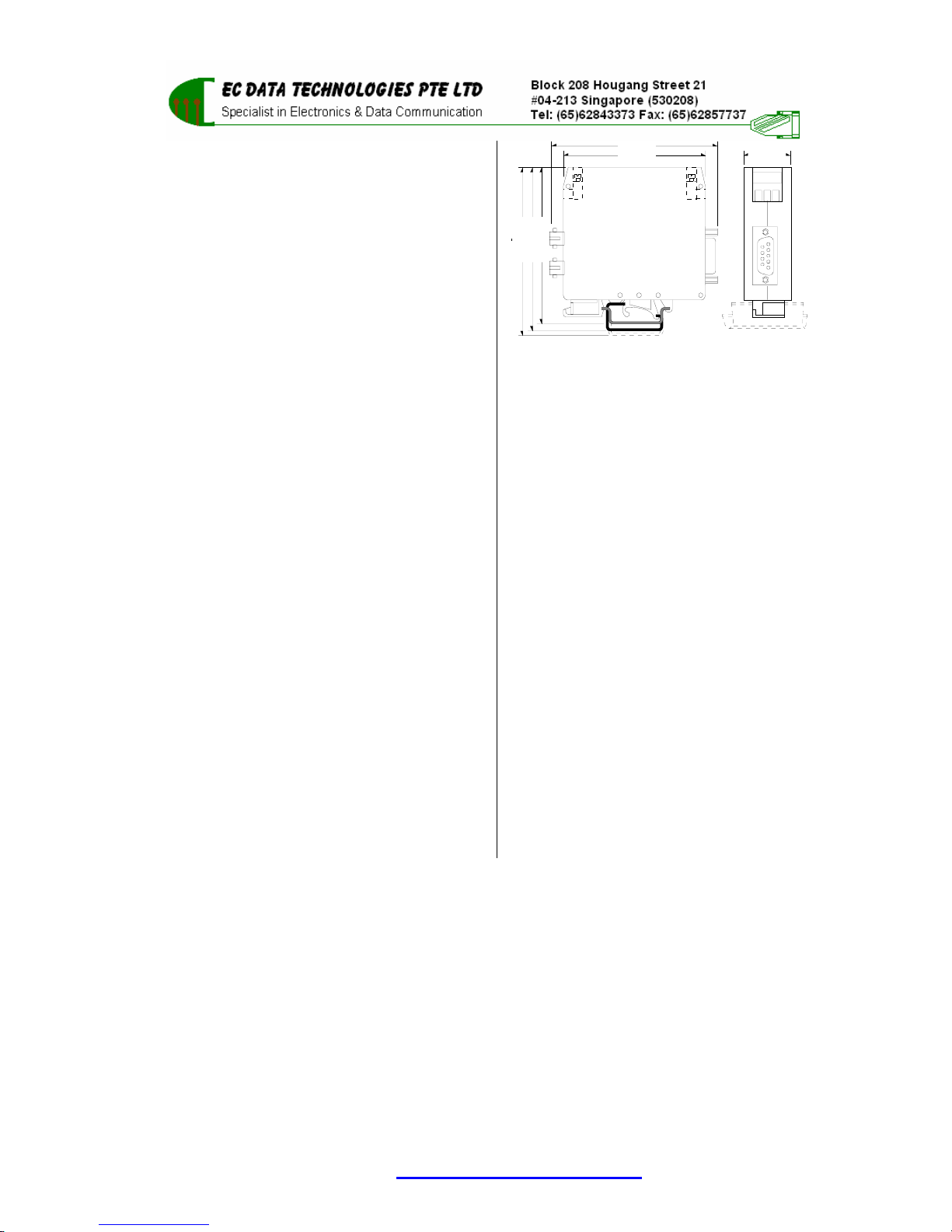
3. TECHNICAL SPECIFICATION
25 (1.0)79 (3.1)
85.5 (3.4)
90.5 (3.6)
93.0 (3.7)
EN 50 022 - 7.5mm
EN 50 035
EN 50 022 - 15mm
98 (3.9)
3.1. Port Description
3.1.1. RS-232; 3-wire RS-232; Signals: Txd, Rxd,
Gnd; Working voltage range ±9vdc; Max volt-
age range ±15vdc; Max surge ±25vdc
3.1.2. Fiber Optics; 820nm over 62.5/125, 100/140,
or 50/125 µm fibers. ST or SMA connectors.
3.1.3. Duplex; Operation can be either half or full-
duplex; No configuration required
3.1.4. Speed; Tested to 115K baud; No configuration
required
3.1.5. Character Setting; Operates with any combi-
nation of parity, data, stop, and start bits; No
configuration required
3.2. Isolation (Per ISO/IEC 9549)
3.2.1. Fiber Optics; intrinsic full isolation
3.2.2. RS-232 to Supply; ; model “-1p” none ; model
“-2p” 2500v (galvanic, 3Kv test)
3.2.3. Casing; dielectric strength per DIN VDE
0303/part 2 is 400kV/cm
3.3. Power Supply
3.3.1. Model ECD232fo-5v-1p; 5vdc ±5%; 50mA
normal operation (120mA during test mode)
3.3.2. Model ECD232fo-5v-2p; 5vdc ±5%; 90mA
normal operation (200mA during test mode)
3.3.3. Model ECD232fo-dv-2p; 9 to 36vdc; 0.75w
normal operation (1.5w during test mode)
3.4. Environmental
3.4.1. Ambient Operating Temperature; 0C to +60C
3.4.2. Ambient Storage Temperature; -40C to
+100C
3.4.3. Relative Humidity; 10 to 90%, non condensing
3.4.4. Casing; fungus and termite resistant
3.4.5. Casing; flame characteristics: self-
extinguishing per UL 94 V2
3.5. Mechanical Dimensions
3.5.1. Height; Width; Depth (See drawing).
3.5.2. Weight; 130g.
3.5.3. Terminal Capacity; 2.5mm strand (12 AWG)
3.5.4. Mounting Rail; DIN EN 50022 (35mm sym)
DIN EN 50025 (32mm asym) Note: removal
from a DIN EN 50025 rail is difficult.
ECD232fo User Manual www.ecdata-tech.com 2 of 2


