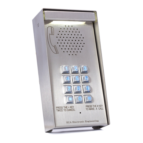
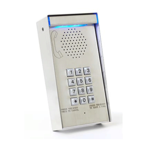
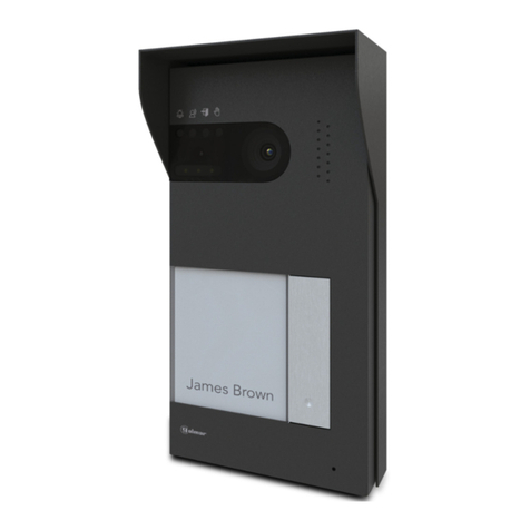
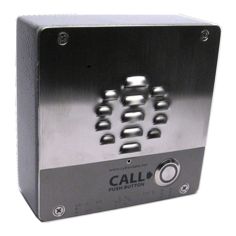
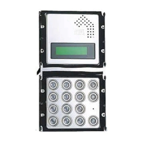
ECA COMMUNICATOR GSM18V82 Operating instructions

CO ICATOR
UU
U
U
U
U
GSM WIRELESS INTERCOM
With
NO RANGE LIMIT
Model: GSM18V82 / Two Channel GSM Intercom
Installation & Owners’ Manual
1.Important! It is a must to read the instructions before installing and programming the unit.
2.HOW THE INTERCOM SYSTEM WORKS
When the call button No. 1 is pressed, the system will announce: “Please wait and your call will be answered shortly”.
Then, the unit will dial the FIRST phone number which was programmed in the memory or the number o rings
that was programmed in the system. I the call was not answered or in case the line was busy, the unit will hang up
and dial the SECOND and THIRD phone numbers which were programmed into the unit’s memory. I there was
no answer to any o the three phone calls, then the unit will announce: “Your call was not answered, please try later”.
When one o the calls is answered by the owner, he can talk with the visitor and open the pedestrian gate by
pressing the HASH (#) key or opening the driveway gate by pressing the STAR (*) key on his phone.
Then, the door station will announce: “The gate is open. Please come in”.
The system will hang-up the call automatically a ter the period o talking time it was set or.
For Button No 2 the unit will per orm the same attempts o calls as described above, but it will dial the 4th , 5th and
6th phone numbers which were programmed into the unit’s memory.
3.HOW THE GSM ACCESS CONTROL WORKS
The unit can be programmed with 1000 phone numbers to become authorized users that are able to open the gate with
their mobile phone with no cost o a call or range limit. When an authorized user calls the SIM card o the unit, the
system will hang-up the call and trigger the relay o the unit to open the gate.
I the person that called was not one o the authorized users, it will just hang up and do nothing.
4.The SIM CARD
You would need a MINI size SIM card to be used with this unit. Insert the SIM card into your mobile phone and
make sure that you can make a call.
=> Phone the SIM card provider and cancel the Message Bank and all the other services on this SIM card.
Note ! Make sure that you always insert or remove the SIM card only when the unit is disconnected from the Power.
1. Insert the SIM card.
2. Connect the GSM antenna. Do not cut or shorten the antenna’s cable. Install the antenna as high as possible and do
not cut or solder its cable. Note! Do not attach the antenna to any metal sur ace. Stick it as high as possible to any
brick wall or wooden ence. You can order a special antenna that is designed to be attached on a metal sur ace i
needed.
3. The unit has two relay outputs, Relay-1 is related to the GSM access control and Relay-2 is related to the intercom
system. Use the Relay-1 outputs (Com.1 and N.O.1) or any electric lock/latch to open the pedestrian gate and use
Relay-2 outputs (Com.2 and N.O.2) to trigger any control panel’s input, to open the driveway gate.
4. Connect 12V - 24V Dc or Ac power supply (Min 2Amp) on terminals PWN1 and PWN2 – no polarity required.
A long BEEP sound will indicate POWER connection. Wait for one minute for the system to register to the network.
If the SIM card is good and active, then the system will announce “The unit is connected to the network”.
If the SIM card fails to log to the GSM network, the unit will announce: “The unit could not connect to the network”.
In such a case, turn the power off, remove the SIM card and insert it to your mobile phone and check if you can make
a call.
5.Program the system as required according to the ollowing owner’s manual.
Important!
SEAL WITH SLICON ALL THE BACK HOLES OF THE DOO STATION TO P OTECT THE UNIT.

Speaker
Output
Call
Button
Mic.
GSM Intercom & Access Control System
Model : GSM18-V21
ECA ELECTRONIC ENGINEERING Pty. LTD.
Tel: 03 - 95720535 Australia.
www.gatesonsolar.com
Optional
Additional
Door Station
Model DS-12
The push button is
not supplied with
the unit and can be
ordered separately.
Optional
Relay 2 - Com.
Relay 1 - N.O. 12V - 24V
Ac / Dc
Min 2Amp
Power Supply
EXI
Push
Button
Relay 1 - Com.
Relay 2 - N.O.
GSM Antenna
Mini
SIM CARD
VR2: Announcement Voice
VR1: GSM Phone Line
Speaker’s Volume
Adjustment
VR2
VR1
Mic.
Input
To the Green wires
of the push button
Connection Diagram

U
U
U
P
P
P
P
D
____________________________________________________________________
1. Programming the phone numbers into the system.
The first three phone numbers in the system are the numbers which the unit will dial when the Call Button No 1 is pressed and the
next 4th, 5th and 6th phone numbers in the memory are for Call Button No. 2. These phone numbers are the first six users of the
GSM access control that are able to open the gate with their mobile phones with no cost of a call.
All the programming and settings of this unit can be done by using any mobile phone to send SMS messages with the following
commands.
ADDING USER’S PHONE NUMBERS BY SMS COMMAND
Use the following format of SMS message to add or change user’s phone numbers in the system:
- The first four letters represent the Password ( P P P P ). he factory default Password is 9 9 9 9
-Followed by the letter “ A ” that represents Adding (or changing) the user’s phone number.
-hen ( U U U ) represent the user’s memory location number, from 001 to 999 followed by the star ( *)symbol.
- And then (N N N …. N N N) represent the phone number followed by the hash ( #) symbol.
Please note!
You can send one SMS message with multiple (more than one) command to add or delete users as the
following format.
=> The following example is to add the first three phone numbers and delete the fourth one:
9999A001*0395720535#,A002*0395720555#,A003*0395720535#,D004#
=> The system will confirm by SMS message to the sender as follows:
A001*0395720535#,A002*0395720555#,A003*0395720535#,D004#CONFIRMED
2. Deleting users’ phone numbers in the system.
You can program a new phone number instead of an old one, by simply programming a new phone number for the
same memory location. The system will automatically delete the old number and replace it with the new user’s phone
number for the same memory location.
Deleting the users’ phone numbers by SMS command.
Use the following format of SMS message to delete user’s phone numbers in the system:
- The first four letters represent the Password ( P P P P ). he factory default Password is 9 9 9 9
-Followed by the letter “ D ” that represents Deleting a user phone number.
-hen ( U U U ) represent the user’s memory location number, from 001 to 999 followed by the hash (#) symbol.
Example of SMS message programming the first
user’s
phone number
which is
0395720535
9999A001*0395720535#
Please Note: The system is sensitive to cases and space between the letters.
The system will confirm the SMS command by sending SMS message to the sender to confirm.
UUU N N
N NNN
. ..
P PP PA
Example of SMS message
DE ETING
the first phone number
in the memory which is
0395720535
9999D001#
=> Please Note: The system is sensitive to cases and space between the letters.

8
0
0
P PP P
90
P PP P
01
P PP P
R
N
How to Delete ALL the users’ phone numbers
You can delete all the users’ phone numbers by sending SMS command as follows:
PPPP represent the four digits password.
The unit will reply by SMS that says: “THIS IS A WARNING. Do you wish to DELETE all phone numbers? “
If you wish to proceed confirm it by sending SMS saying: YES
The unit will send back SMS that say: “
All phone numbers were deleted
”.
=> Please NOTE
Ignoring the warning message and not confirming it by “ YES ” message within two minutes will cause the system to
disregard the last command and the phone numbers would be saved and not be deleted.
3. Confirmation SMS service by the unit
The unit will reply by SMS message to each SMS command that was received to inform the sender if the command
SMS message that was received was Confirmed or Failed. This service can be cancelled so that the unit does not send
any SMS messages EXCEPT for SMS command of Deleting all phone numbers. The factory default setting is to send
SMS reply to the sender which would be repeating the SMS message command sent followed by the word
CONFIRMED or FAILED at the end of the message.
How to Cancel or Activate the SMS service in the unit
You can Cancel or Activate the SMS service of the unit by sending SMS command to the unit as follows:
The letters
PPPP
represent the four digits Password.
To cancel; send SMS
To Activate; send SMS
The unit will send confirmation SMS to the sender accordingly.
4. How to choose the number of Rings for the first three phone numbers
You can select the number of rings (from 1 to 9 rings) that the unit would wait for an answer, before it hangs up and
dials the 2
nd
and the 3
rd
phone numbers.
The factory default is 5 Rings (about 15 seconds) for each one of the first three phone numbers.
How to change the number of Rings by SMS command
You can change the number of Rings by SMS command for each of the three phone number in the system as follows:
The letters “ PPPP ” represent the 4 digit PASSWORD.
The letter “ N “ represents the number 1 2 or 3 for the first second and third phone number in the memory.
The letter “ R “ represents the numbers of Rings from 1 to 9. The factory default is 5.
Example:
The following SMS example shows how to program 7 Ring tones for the 3
rd
phone number in the memory:
The unit will send confirmation SMS to confirm accordingly.

N
P PP
P
1
0
0
F
2
P PP P
N
P PP P
N
0
6
5. How to select the Relay for the PUSH BUTTON input.
The Push Button Input can activate Relay-1 or Relay-2 according to the function that was chosen for the relay.
The factory default setting for the Push Button Input is to activate RELAY-1 according to the function chosen.
You can change this setting by SMS command as follows:
The letters “ PPPP ” represent the 4 digit PASSWORD.
The letter “ N “ represents the numbers 1 or 2 for Relay-1 or Relay-2 accordingly.
The unit will send confirmation SMS to confirm.
6. How to choose the Relays’ function; Pulse or Latch
For each one of the relays 1 and 2 you can choose one of the following two functions;
MOMENTARY (PULSE) or LATCH function (ON / OFF).
The factory default setting for both the relays is a MOMENTARY function (with a 4 second PULSE).
You can change the sending the SMS command as follows:
The letters “ PPPP ” represent the 4 digit PASSWORD.
The letter “ N “ represents the Number 1 or 2 for Relay-1 or Relay-2.
The letter “ F “ represents the FUNCTION 1 for Momentary or 2 for Latch.
The unit will confirm by SMS message to the sender accordingly
.
7. How to set the Relays’ PULSE time interval
For each one of the relays 1 or 2 you can choose the time interval of the pulse for the momentary function.
The factory default setting for both the relays is a 4 second PULSE.
You can choose the TIME interval for each one of the relays by SMS command as follows:
The letters “ PPPP ” represent the 4 digit PASSWARD.
The letter “ N “ represents the Number 1 or 2 for Relay-1 or Relay-2.
The letter “ T “ represents the PULSE time:
Enter: 0 => for ½ a second pulse time.
Enter: 1 => for 1 second pulse time. (Factory Default for Relay 2).
Enter: 2 => for 2 second pulse time.
Enter: 3 => for 3 second pulse time.
Enter: 4 => for 4 second pulse time. (Factory Default for Relay 1).
Enter: 5 => for 5 second pulse time.
Enter: 6 => for 6 second pulse time.
Enter: 7 => for 7 second pulse time.
Enter: 8 => for 1 second pulse time.
Enter: 9 => for 15 second pulse time.
The unit will send confirmation SMS to confirm accordingly.
8. To Lock & Unlock the unit;
The unit can be LOCKED so that it will not operate or make any calls and announce “wrong command” for any attempt
to make a call or open the gate.
To LOCK or UNLOCK the unit send the following SMS command:
The letters “ PPPP ” represent the 4 digit PASSWORD.
The letter “ N ” represent “ 1 “ for LOCK and “ 2 “ for UNLOCK.
The unit will confirm by SMS to the sender that says: “ The system is locked” or “The system is unlocked “ accordingly.

1
1
P PP P
P PP P
1
N
0
3
2N03
P PP P
9. HOLD Command
The user can send SMS command and overtake control of a relay and keep it active (ON) until cancelation command is
received for each one of the two relays.
When the relay is in HOLD mode it will not function to any other command until a cancelation command is received.
Instead of activating the relay the unit will send SMS to the user that says “Hold Command is Active” if the user
tried to open the gate with his mobile phone.
=> The user can send SMS of HOLD COMMAND to overtake control of any one of the two relays as follows:
To send HOLD command by SMS
To Cancel the HOLD command by SMS
PPPP represent the 4 digit PASWORD.
The letter “ N ” represents relay 1 or relay 2.
Example of SMS HOLD command for relay 2: 9999**03*21#
The unit will send SMS to the sender to confirm Hold Command as follows: “Confirming Relay 2 is Active ON”
Example of SMS canceling HOLD command for relay 2: 9999**03*22#
SMS confirming t of cancelling Hold Command will be received as follows: “Confirming Relay 2 is no longer Hold Active”
You can send one SMS to cancel both Hold commands for both the relays as follows: 999**03*12# **03*22#
You can send one SMS to cancel both Hold commands for both the relays as follows: 9999**03*12# **03*22#
10. How to limit the Talking Time
You can select and limit the talking time with the visitor by SMS command.
The factory default limit time is 59 second (before the next flag fall).
The system will end up each call (after the chosen “Talking Time”) by an announcement: “ END OF CALL” .
To change the talking time by SMS command send the SMS as follows:
The letters “ PPPP ” represent the 4 digit PASWORD.
The letters “T T “ represent the time in seconds according to the table below:
Enter: 0 0 => for Zero talking time
;
Enter: 3 0 => for 30 seconds talking time
;
;
Enter: 5 9 => for 59 seconds talking time (Default)
Enter: 6 1 => for 1 Minute talking time
Enter: 6 2 => for 2 Minutes talking time
Enter: 6 3 => for 3 Minutes talking time
;
;
Enter: 6 9 => for 9 Minutes talking time
Enter: 7 0 => for 10 Minutes talking time
Enter: 9 9 => for unlimited talking time. (Not recommended).
The unit will confirm by sending SMS message to the sender as follows: “Confirming the talking time was changed “
11. How to check the next available empty memory cell in the system
In order to get the next available empty memory position in the system by SMS command send SMS as follows:
PPPP represent the 4 digit PASWORD.
The unit will send SMS reply to the sender that says: “ The nest available position is X X X “
The letters X X X represent three digit number (such as 055) to indicate the empty memory position.

1
2
P PP P
N
1
3
P PP P
0 1 2 3 4 5
P PP P
1
4
W WW W
12. How to CHECK the GSM reception level in the area by SMS command
The unit will send SMS replay with the GSM reception level of the unit in the area by the following SMS command:
The unit will reply to the sender with SMS message: “The reception level is X “
The letter “ X” represents a number from “ 0 “ to “ 5 “ .
13. OPEN TO ALL command
The unit can be programmed so that it will open the gate to ANY incoming call (without checking if the caller is
authorized user). You can activate or cancel this function by SMS command as follows:
PPPP represent the 4 digit PASSWORD.
The unit will reply by the following SMS to the sender:
When the OPEN TO ALL is activated the system will send SMS saying: Open to all is activated.
When the OPEN TO ALL is cancelled the system will send SMS saying: Open to all is cancelled.
14. How to change the PASSWORD
The factory default password is 9999.
You can change the password by sending the following SMS message:
The letters P P P P represent the old password
The letters W W W W represent the new password.
The unit will confirm by SMS replay: “The new password is X X X X”
The letters X X X represent the new password.
15. How to set the system to factory default settings.
To set the unit to “Factory Default Settings” means the unit will delete all the phone numbers rest all the functions
to factory default parameters as was supplied initially.
To do set the unit to Factory Default you need to send the following SMS command:
PPPP represent the four digits password.
The unit will reply by SMS back that says: “THIS IS A WARNING. Do you wish to DEFAULT the system? “
You should confirm within 2 minutes by sending SMS message that says YES if you wish to proceed otherwise
the system will ignore this command and do nothing.
If confirmed then the unit will send back SMS that says: “The unit was set to ECA Factory Default”.
All Rights Reserved to
ECA
Electronic Engineering Pty LTD.
Table of contents
Other ECA Intercom System manuals
